Paul Taylor Opened the Lines of Telecommunication for the Hearing-Impaired

These days, nearly everyone communicates through some kind of keyboard, whether they are texting, emailing, or posting on various internet discussion forums. Talking over the phone is almost outmoded at this point. But only a few decades ago, the telephone was king of real-time communication. It was and still is a great invention, but unfortunately the technology left the hearing and speaking-impaired communities on an island of silence.
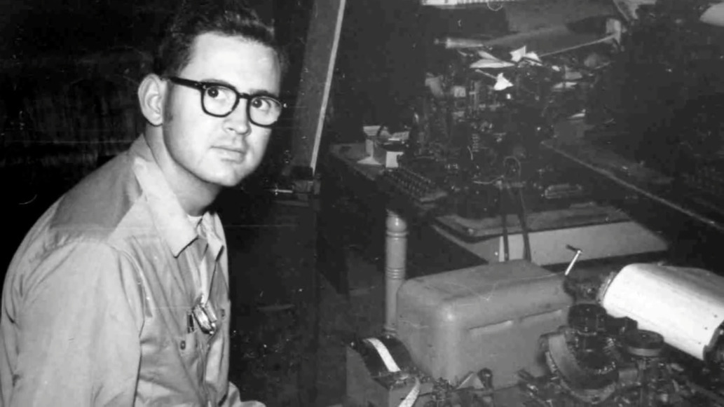
Paul and an early TDD. Image via Rochester Institute of Technology

Engineer and professor Paul Taylor was born deaf in 1939, long before cochlear implants or the existence of laws that called for testing and early identification of hearing impairment in infants. At the age of three, his mother sent him by train to St. Louis to live at a boarding school called the Central Institute for the Deaf (CID).

Here, he was outfitted with a primitive hearing aid and learned to read lips, speak, and use American sign language. At the time, this was the standard plan for deaf and hearing-impaired children — to attend such a school for a decade or so and graduate with the social and academic tools they needed to succeed in public high schools and universities.

After college, Paul became an engineer and in his free time, a champion for the deaf community. He was a pioneer of Telecommunications Devices for the Deaf, better known as TDD or TTY equipment in the US. Later in life, he helped write legislation that became part of the 1990 Americans with Disabilities Act.

Paul was diagnosed with Alzheimer’s in 2017 and died in January of 2021 at the age of 81. He always believed that the more access a deaf person had to technology, the better their life would be, and spent much of his life trying to use technology to improve the deaf experience.

High school-aged Paul. Image via YouTube

Learning to Speak Without Hearing

Soon after three-year-old Paul started school at CID, he met a little girl named Sally Hewlett who would one day become his wife. Along with their classmates, they spent the next several years learning to speak by holding their hands to the teacher’s face to feel the vibrations of speech, then touching their own faces while mimicking the movement and sound.

Paul’s father died while he was still in school. His mother moved to St. Louis to be with her son so he could still attend, but live at home. She took the opportunity to study at CID and she became an accredited teacher for deaf children. When it was time for high school, Paul and his mother moved to Houston, where she started a school for the deaf, and he enrolled in public school for the first time. Paul had no interpreter, no helper of any kind.

In a 2007 documentary made by the Taylors’ youngest daughter, Paul tells a story about an experience he had in high school. There was a nice looking girl in his class, and he wanted to know more about her, so he asked a different girl who she was. When that girl offered to give Paul the first girl’s telephone number, he stopped in his tracks, realizing at that moment how different he was because he couldn’t use the phone like all the other kids. The experience stuck with him and helped drive his life’s work.
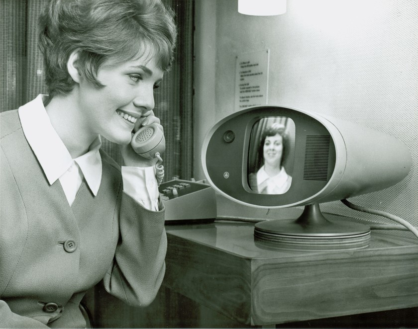
AT&T’s Picturephone as it premiered at the 1964 World’s Fair. Image source: AT&T Archives and History Center via LA Times

Phones for All

After high school, Paul completed his bachelor’s of chemical engineering degree from the Georgia Institute of Technology in 1962 and moved back to St. Louis to earn a master’s degree in operational research at Washington University. In the meantime, Sally, who had gone to high school in St. Louis, earned her bachelor’s degree in home economics and returned to CID to teach physical education, religion, and home economics. When Paul learned that Sally was living in town, he got in touch with her immediately. They started dating and were engaged six months later.

Paul took Sally to the 1964 World’s Fair in Queens, New York for their first anniversary. They marveled at AT&T’s Picturephone and wished the future would arrive sooner so they could easily talk from anywhere by reading each other’s lips. By day, Paul was an engineer at McDonnell Douglas and later, Monsanto. He was a different kind of engineer at home, devising different ways to help raise their three hearing children. After their first child was born, Paul built a system that would blink the lights in the house to let them know the baby was crying.

Paul, Sally, and their son David along with one of the first teletypewriters that was repurposed as a telecommunication device for the deaf. Image via Rochester Institute of Technology

He also did whatever he could to help the deaf community by volunteering his time. The phone problem still bothered him greatly. When he noticed an old Western Union teletype machine from WWII just sitting around collecting dust, he got the idea to turn it into a new kind of communication tool.

Around the same time, a deaf physicist named Robert Weitbrecht was developing an acoustic coupler that would transmit teletype signals over consumer phone lines. Paul got Weitbrecht to send him one and created one of the first telecommunication devices for the deaf (TDD). With one of these devices on each end of the phone line, anything typed on one would be printed out on the other. Paul worked with Western Union to get these old teletypewriters into the hands of hearing and speaking-impaired people, and convinced AT&T to create a relay service to use them as well.

Paul started a non-profit organization to distribute these early TDDs to other deaf St. Louisans. He asked a local telephone wake-up call service to help out, and built one of the first telephone relay systems in the process. Although both parties needed a TDD to be able to communicate, this was a big step in the right direction.

Paul also did a lot of work to keep the machines humming for the people who depended on them. Teletypewriter manuals were helpful, but were awfully dense reading material for the layman. Paul organized a week-long workshop to create a picture-rich manual called Teletypewriters Made Easy to help people repair and maintain three common models of teletypewriter. Paul discusses his personal history with TDD development in the video below.

A Loud Voice for the Deaf Community

In 1975, Paul was offered a position at the National Institute for the Deaf at Rochester Institute of Technology, so the Taylor family moved to upstate New York. Paul became a computer technology professor and chairman of the Engineering Support team. He stayed there for the next 30 years before retiring.
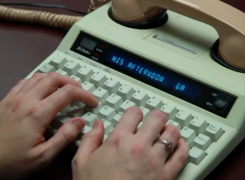
A more modern TTY. Image via YouTube

During this time, he advocated for a national, operator-assisted telephone relay service through which deaf and hearing impaired people could communicate with anyone, whether or not the other person had a TDD.

The idea was that the deaf person would use a TTY to call an operator, who would get the other person on the line and relay messages back and forth between the two parties by typing out what the voice caller said and reading aloud what the TDD user typed in response. Paul took a two-year leave of absence from teaching and worked directly with the FCC to write regulations that became part of the guidelines prescribed in the 1990 Americans with Disabilities Act (ADA).

Learning How to Hear

At the age of 65, Paul and Sally decided to get cochlear implants after a lifetime of silence. Their youngest daughter Irene made a documentary about their experience called Hear and Now, which is embedded below. It’s an interesting firsthand look into the process, which is not the instant cure that the internet may have led you to believe. The implant can’t be activated until the swelling from surgery goes down, which takes about a month. And it can take years for the brain to get used the new sensory information and begin to distinguish relevant sounds from background noise.

Although TTY/TDDs are falling out of use thanks to the videophone-enabled text messaging devices in most people’s pockets, their influence on communication lives on in shorthand now used in our everyday messages — OIC, PLS, and THX are older than you might think.

Thanks for the tip, [Zoobab].
source https://hackaday.com/2021/02/23/paul-taylor-opened-the-lines-of-telecommunication-for-the-hearing-impaired/

Useful Build Tips For Making LED Panel Frames

[NotLikeALeafOnTheWind] has created many LED-based display projects, and shares his method for making attractive LED panel frames and mounts. At first glance it may look as though slapping a rectangle of aluminum extrusion around a display is all it takes, there is also the mounting and management of wiring, power supply, and possibly a Raspberry Pi to deal with. The process of building an attractive frame also has a few hidden gotchas that can be avoided with a bit of careful planning.

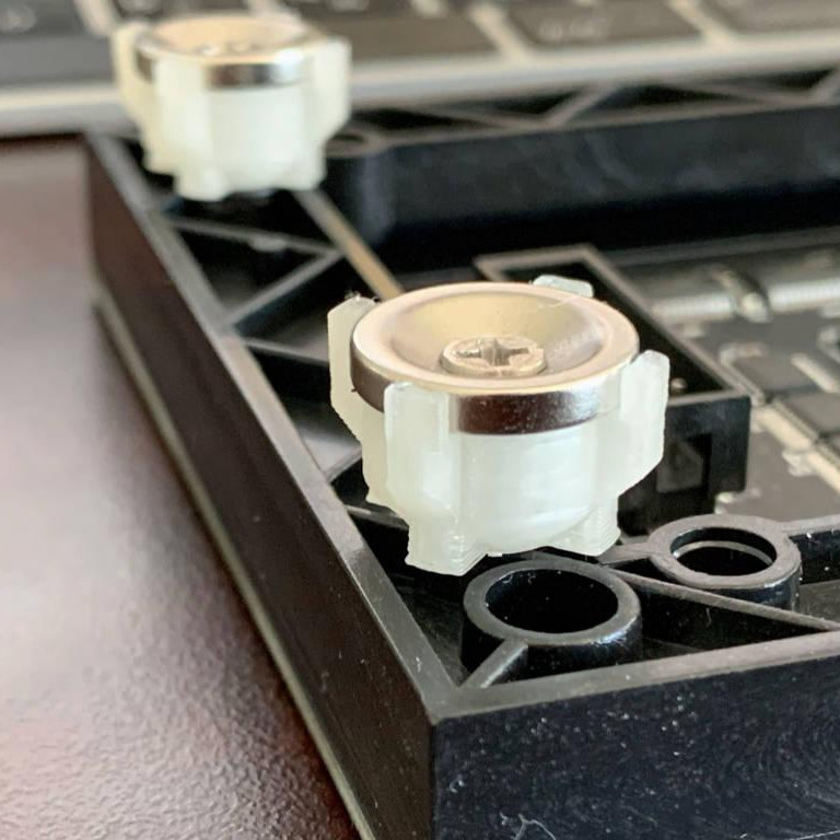
Magnetic feet on the LED panels makes mounting much easier and more flexible.

Here is one tip that will resonate with some readers: don’t rely on specified dimensions of parts; measure the actual parts yourself. There can be small differences between what a data sheet says to expect, and the dimensions of the actual part in one’s hands. It may not be much, but it can be the difference between an ideal fit, and something that looks like a bit of a hack job.

[NotLikeALeafOnTheWind] provides some basic frame layouts, and suggests using two- or three-channel extrusions to provide a flat bezel around the display edge if desired. Mounting the LED panel itself is done with magnetic feet and providing a length of steel bar to which the display can attach. This can provide a flush mount while avoiding the whole issue of screw-mounting the display panels themselves, or sliding them into channels. For mounting all the other hardware, a piece of DIN rail and some 3D-printed parts takes care of that.

The result looks slick and sturdy, and some of the tips are sure to be useful even if the whole process isn’t applied. We like the way the basic design scales and is flexible about the thickness and size of the LED panels themselves, making it a promising way to accommodate perfectly functional oddball panels that end up in the trash.

source https://hackaday.com/2021/02/23/useful-build-tips-for-making-led-panel-frames/

Hands on With the Ortur Laser Cutter

I couldn’t write very much without a computer. Early in my career, I wrote with a typewriter. Unless you are pretty close to perfect — I’m not — it is very frustrating to make edits on typewritten stuff. The equivalent in the real world, for me, has been 3D printers and CNC machines. I can visualize a lot of things that I’m not careful enough to build with normal tools. Despite my 7th-grade shop teacher’s best efforts, everything I did turned out to be a toothpick or a number 7. But I can get my ideas into CAD and from there the machines do the rest. That’s why I was excited to get a laser cutter this past Christmas. You might wonder why I’d need a laser cutter if I have the other tools. Then again, if you read Hackaday, you probably don’t need me to explain why you need a new gadget. I’ve had my eye on a laser for a good long time, but recent developments made it more attractive. I thought I’d share with you some of what I’ve found getting started with the Ortur laser cutter. The cutter is easy to put together and costs somewhere in the $200-$400 range depending on what you get with it. I thought I’d take some time to share what I’ve learned about it.

Why a Laser?

If you haven’t had experience with a laser cutter or engraver before, you might think it is a very specific instrument. Sure, the Ortur is good at engraving some things (but not all things). It can cut some things, too, but not as many things as a big serious laser cutter. However, creative people find lots of ways to use cutting and engraving to produce things you might not expect.

For example, if you surf YouTube, you’ll find people who put spray paint on either a ceramic tile or a canvas and then burn some or all of the paint away to make really interesting artwork. Sometimes they’ll even use multiple layers of paint to create different colors by burning different depths into the artwork. Another multicolor technique is to cut what amounts to a custom stencil in masking tape that is already applied to the part. You can then spray paint, remove the tape, apply fresh tape, and cut a new stencil for another color. Some people etch the backs of mirrors. It is also surprisingly handy to be able to precision cut paper and cardboard. However, with some practice and technique, you can even cut some thicknesses of plywood.

I’m very interested in creating PC boards either directly or by cutting resist and then using conventional etching techniques. People are doing that, too. Depending on the power of your laser, you can cut quite a few things, although with a visible laser, you can’t cut things that are transparent. You can engrave more things, and even metal if you use some additional chemicals (like mustard). In addition to line art and text, you can do halftone images from pictures. If you have a powerful enough laser, you can even make glass, sort of.

Of course, in addition to all the artsy things, you can just cut material too, which is surprisingly handy. [Electronoobs] did a video last year experimenting with different materials with a 15W laser so that will give you some idea of what you can and can’t cut with this type of laser.

There are some things you shouldn’t cut because they emit noxious fumes like ABS or vinyl products. Leather engraves and cuts well but boy does it stink! I understand that you should be careful working with chrome tanned leather, too, because the tanning chemicals could emit bad fumes. Some materials are also too prone to bursting into flames like styrofoam.

About the Ortur

If you want a laser, your next problem is which one to buy. There are carbon dioxide lasers that are commonly available, but they are pretty pricey and are known to need a lot of effort — including a bucket of ice of water and ventilation — to use. Semiconductor lasers are cheap and much easier to use. These are generally visible which, as I mentioned, means you can’t use them to cut some things like clear acrylic. You can get some very inexpensive laser engravers, but many of them are probably not going to cut much.

Then again, power isn’t everything. Broadly speaking, you can trade time for power with a laser. That is, a cut that might take a 10 watt laser a few seconds in a single pass might take a 1 watt laser four or five 30-second passes. It isn’t always simple because as the laser chars material it creates a barrier that prevents you from getting as much energy underneath. Still, you can sometimes do the same job with lower power if you are willing to take longer per pass and repeat the pass.

The Ortur Laser Master 2 is reasonably priced and has three choices in laser power: 7W, 15W, and 20W. This is a little deceptive because the power is actually the input power to the module. The 15W unit, for example, produces less than 5W of output power, but that’s still able to do a lot more than you might think.

The device is made to work with a free piece of Windows software called LaserGRBL that talks to the onboard GRBL controller. In theory, anything that would send G-code could work. I use Linux, so I opted for LightBurn which is excellent and well worth the $40 you’ll pay for it. It runs on multiple platforms, too, but sadly not on the Raspberry Pi, so I’ve had to drag a laptop out to work with the Ortur. You might also check out LaserWeb.

There are other cheap laser engravers and cutters, but I was impressed with the Ortur’s size and capabilities. There’s also a lot of add on designs available for it and good support in software.

Assembly

The unit requires some assembly, although much of it is preassembled. You build a frame of aluminum extrusions and then slip the X carriage on. There’s a 32-bit controller board and some stepper motors. The 32-bit board is a big selling point. Some of the work you do with the laser requires PWM to modulate the beam’s power. Most 8-bit boards will allow you to step power from 0-255 so each step is about 0.4% of full strength. A 32-bit board will let you do around 1,000 divisions of full scale which gives you about 0.1% on each step.

The mechanism is like a plotter or a 3D printer with no Z-axis. Since the laser doesn’t touch anything, it doesn’t need the robustness of a CNC setup. Of course, you can also mount a laser to a 3D printer or a CNC machine if you already have one and that’s not necessarily a bad option, although most of those setups have some limitations (for example, no modulation of beam intensity).

The best way to see how to build the machine is to watch the company’s video instructions (see below). There are a few things unclear in the video and I made some notes that might help you. There are also plenty of 3rd party build videos on YouTube.

First Cuts

The urge to cut something is overwhelming when you get the unit complete. However, be sure you have eye protection and plenty of ventilation. You should probably have a spray bottle of water and a fire extinguisher, too (you can see one of my fire extinguishers in the video below). Things do catch on fire under a laser, so be prepared. If you do get a little flame, try the water first since the extinguisher will make a huge mess.

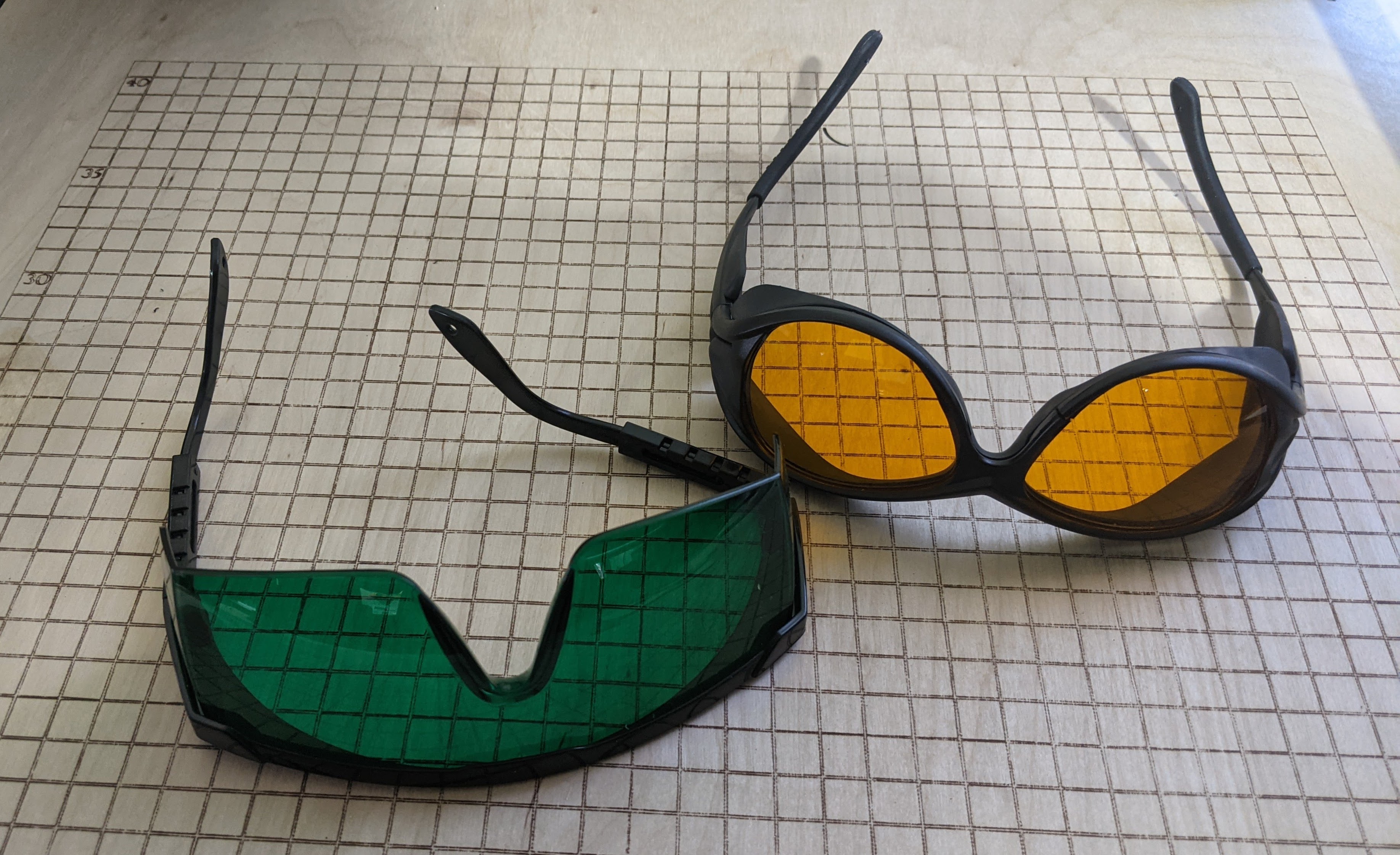
The glasses that come with the cutter seem to be adequate and some people have tested them by firing the laser through them. However, I opted for some better-quality glasses. Your eyes are worth more than a few bucks you can save with cheap glasses.

Be sure you have the latest firmware. My unit predated the January 2021 update and the fan did not run unless the laser was also running. I would guess this would shorten the laser diode’s life. With the updated firmware, there is smarter fan management along with some other fixes. The update is as simple as dragging and dropping a file, but for some reason, it only works under Windows. Linux sees the USB drive and will do the copy but it doesn’t stick. At least it didn’t brick the cutter.

Regardless of firmware, before you can cut, you’ll need to set the focus correctly. If you are like me, you are probably thinking: “Focus? You don’t focus a laser.” Well, turns out you do focus a cheap laser.

Focus is Everything

To get the required energy to the workpiece, the semiconductor laser passes through a lens that focuses the beam to — more or less — a point. That point is what does all the cutting or engraving. That means the piece you want to work with has to be at that focal point. After the lens, the beam will look like an hourglass and the further you are from the pinch in the hourglass, the less cutting you’ll do.

The Ortur’s laser doesn’t move up and down but the lens can either screw in and out a few millimeters or push in and out, depending on which one you have. Once you have something under the cutter, you can put some black construction paper over it and use that to visualize the focus. The software you are using will have a button to turn the laser on at low power. Using the glasses will help reduce the spillover and you’ll be able to see the main part of the beam easily on the black paper.

Some people use a USB microscope or other magnification to get the best focus. However, I didn’t like the stock method for focusing. The lens ring is hard to turn and even if you 3D print your own ring, it is awkward to spin the lens around. It also doesn’t afford you much range.

Luckily, there are many 3D printed solutions to create a moving laser head on the Ortur. I’ll show you the one I’m using next time. For now, assume you are going to focus the lens yourself. That limits the height of things you can cut or engrave, too, although some people put the machine on blocks to make more room underneath. A tight focus will let you cut or engrave quicker and make the cut line finer, too. However, even if you are a little off, you can usually get some result. It is a good idea to tape your work down or clamp it so if you need to you can do a second pass without moving anything.

There are different lenses you can get for the laser. The one the 15W machine comes with has a focal length of about 55 mm. However, there are other lenses — the G8 is popular — that have different focal lengths. Each lens has different characteristics as far as how tight they can focus and how many elements they have (more elements means less overall power).

The power delivered to your part is a combination of the beam power, the quality of the focus, and the time spent. Even the time it takes for the laser to change direction can cause a deeper burn or cut which is why most software offers an overscan function that keeps the laser off and away from the cut line when it changes direction.

If you are careful about focusing, you should be able to get a pretty good engraving on a piece of cardboard. Be sure to have something under it since you might cut through and leave a permanent mark. I mounted my cutter on a piece of plywood and I deliberately marked a grid on the board. I’ll tell you more about those additions next time.

Sometimes, you deliberately want to defocus a little to get wider lines. [Geordie_h] talks about this trick, along with some other pro tips that are aimed for a more commercial cutter, but still apply to the Ortur and other similar lasers.

Next Time

Speaking of next time, there’s a lot more to talk about. In addition to mounting the device and making the laser head move, I wanted to add air assist — something I’m still working on. This clear smoke from the cut as well as fine ash, allowing the laser to hit fresh material while cutting.

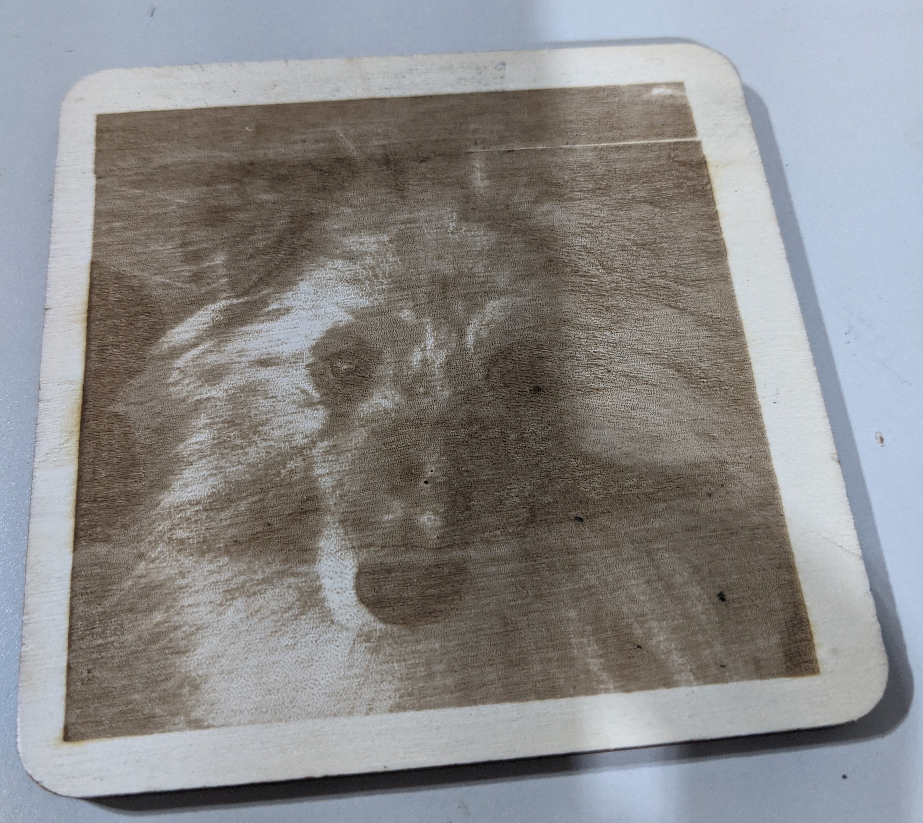
For some reason my machine will often stall on long cuts, and from reading the Internet, I’m not alone. Changing USB cables seemed to help. It may need a slightly beefier power supply or grounding on the frame. Then again, it could be power settings on my laptop. Time will tell. This has been particularly a problem when doing images that require a lot of time. You can see my picture of Rocky has a little misalignment at the top where I restarted after a failure like this and didn’t quite get it lined up right.

The Ortur reminds me of early 3D printers. It works, but it needs some work to get it to work well. But, for me at least, that’s the fun part anyway.

source https://hackaday.com/2021/02/23/hands-on-with-the-ortur-laser-cutter/

Lighted Raspberry Pico Stream Deck is Easy as Pi

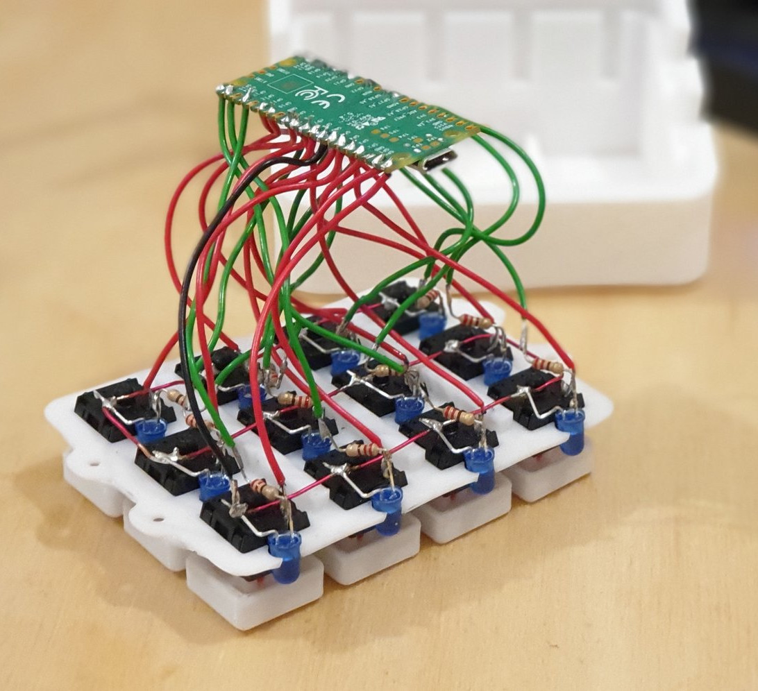
Whether it’s for work, school, fun, or profit, nearly everyone is a content-creating video producer these days. And while OBS has made it easier to run the show, commanding OBS itself takes some hotkey finesse. Fortunately, it just keeps getting easier to build macro keyboards that make presenting a breeze. That includes the newest player to the microcontroller game — the Raspberry Pi Pico, which [pete_codes] used to whip up a nice looking OBS stream deck.

Sometimes you just need something that works without a lot of fuss — you can always save the fuss for version two. [pete_codes]’ Pico Producer takes advantage of all those I/O pins on the Pico and doesn’t use a matrix, though that is subject to change in the future. [pete_codes] likes the simplicity of this design and we do, too. You can see it in action after the break.

In reply to the Twitter thread, someone mentions re-legendable keycaps instead of the current 3D-printed-with-stickers keycaps, but laments the lack of them online. All we can offer is that re-legendable Cherry MX-compatible keycaps are definitely out there. Maybe not in white, but they’re out there.

If [pete_codes] wants to go wild in version two and make this macro keeb control much more than just OBS, he may want to leave the labeling to something dynamic, like an e-ink screen.

source https://hackaday.com/2021/02/23/lighted-raspberry-pico-stream-deck-is-easy-as-pi/

Lighted Raspberry Pico Stream Deck is Easy as Pi

Whether it’s for work, school, fun, or profit, nearly everyone is a content-creating video producer these days. And while OBS has made it easier to run the show, commanding OBS itself takes some hotkey finesse. Fortunately, it just keeps getting easier to build macro keyboards that make presenting a breeze. That includes the newest player to the microcontroller game — the Raspberry Pi Pico, which [pete_codes] used to whip up a nice looking OBS stream deck.

Sometimes you just need something that works without a lot of fuss — you can always save the fuss for version two. [pete_codes]’ Pico Producer takes advantage of all those I/O pins on the Pico and doesn’t use a matrix, though that is subject to change in the future. [pete_codes] likes the simplicity of this design and we do, too. You can see it in action after the break.

In reply to the Twitter thread, someone mentions re-legendable keycaps instead of the current 3D-printed-with-stickers keycaps, but laments the lack of them online. All we can offer is that re-legendable Cherry MX-compatible keycaps are definitely out there. Maybe not in white, but they’re out there.

If [pete_codes] wants to go wild in version two and make this macro keeb control much more than just OBS, he may want to leave the labeling to something dynamic, like an e-ink screen.

source https://hackaday.com/2021/02/23/lighted-raspberry-pico-stream-deck-is-easy-as-pi/

Lighted Raspberry Pico Stream Deck is Easy as Pi

Whether it’s for work, school, fun, or profit, nearly everyone is a content-creating video producer these days. And while OBS has made it easier to run the show, commanding OBS itself takes some hotkey finesse. Fortunately, it just keeps getting easier to build macro keyboards that make presenting a breeze. That includes the newest player to the microcontroller game — the Raspberry Pi Pico, which [pete_codes] used to whip up a nice looking OBS stream deck.

Sometimes you just need something that works without a lot of fuss — you can always save the fuss for version two. [pete_codes]’ Pico Producer takes advantage of all those I/O pins on the Pico and doesn’t use a matrix, though that is subject to change in the future. [pete_codes] likes the simplicity of this design and we do, too. You can see it in action after the break.

In reply to the Twitter thread, someone mentions re-legendable keycaps instead of the current 3D-printed-with-stickers keycaps, but laments the lack of them online. All we can offer is that re-legendable Cherry MX-compatible keycaps are definitely out there. Maybe not in white, but they’re out there.

If [pete_codes] wants to go wild in version two and make this macro keeb control much more than just OBS, he may want to leave the labeling to something dynamic, like an e-ink screen.

source https://hackaday.com/2021/02/23/lighted-raspberry-pico-stream-deck-is-easy-as-pi/

Pelton Turbine Development For An Air Powered Model Helicopter

[Tom Stanton] has been messing around with compressed air power for a few years now, and most of his work focused on piston engines. He likes using 2-liter soda bottles as lightweight tanks but their capacity is limited, so the nozzle can be a maximum of 1 mm in diameter if he wants to produce thrust for 30 seconds or longer using a turbine. Pelton turbines have been in use for a long time, especially for hydroelectric systems, and they use small diameter nozzles, so he decided to experiment with a pneumatic Pelton turbine. (Video, embedded below.)

Pelton wheels are water wheels with specially designed buckets to efficiently extract energy from a high-velocity jet of water. [Tom] 3D printed several geared Pelton turbines and started doing bench tests with a propeller and a load cell to gather empirical data. With the help of high-speed video of the tests, he quickly realized that the turbine efficiency is highly dependent on the load. If the load is too small or too large, the moving air will not come to a complete standstill, and energy will be wasted. [Tom] also suspected that some moving air was escaping from the bucket, so he created a version that enclosed the buckets with a ring on the outer perimeter, which increased the peak thrust output by 65%. Compared to his diaphragm air engine design, the peak thrust is higher, but the overall efficiency is less. [Tom] believes there is still room for improvement, so he plans to continue working on the Pelton turbine concept, with the hopes of building an air-powered model helicopter that can lift off.

One comment that came up a few times with his piston engine designs is whether venting the air straight out the nozzle, without a turbine or engine in the way, would be a better option. [Tom] tested this in the bench, and the straight-through nozzle was four times less efficient than the turbine. The reason for this was addressed in the comments on our article on diaphragm air engine and discussed on the Hackaday podcast. It’s an impedance matching problem, and an engine or turbine converts the small volume of high-velocity air into a large volume of low-velocity air.

source https://hackaday.com/2021/02/23/pelton-turbine-development-for-an-air-powered-model-helicopter/

LED Spectrum Visualizer Driven By Raspberry Pi

Back in the 1980s, spectrum displays on audio equipment were absolutely must have, and the aesthetic came to define the era. This lingered on through the 1990s, and remains a cool look even to this day. [Arduino Guy] decided to put together such a display using a Raspberry Pi and a large LED display.

The LED display in question is of the 64×64 RGB type, available from Aliexpress and other electronics suppliers online. To run the display, an Adafruit RGB Matrix Hat is used with the Raspberry Pi 3B, which makes driving the panel a cinch. The visual effect is run via a Python script, which plays a wave file and produces the spectrum graphics via a Fast Fourier Transform.

While the code isn’t able to act as a general-purpose equalizer display for any content played on the Raspberry Pi, creating such a script could be an entertaining exercise for the reader. Alternatively, the Pi could be hooked up to a microphone to run the display based on ambient room noise. In any case, we’ve seen great projects like this before, such as this laser-based display. Video after the break.

source https://hackaday.com/2021/02/22/led-spectrum-visualizer-driven-by-raspberry-pi/

3D Print a PCB the Hard Way

There’s an old joke about the physics student tasked with finding the height of a building using a barometer. She dropped the barometer from the roof and timed how long it took to hit the ground. Maybe that was a similar inspiration to [Moe_fpv_team’s] response to the challenge: use a 3D printer to create a PC board. The answer in that case? Print a CNC mill.

[Moe] had some leftover 3D printer parts. A $40 ER11 spindle gets control from the 3D printer software as a fan. The X, Y, and Z axis is pretty standard. The machine can’t mill metal, but it does handy on plywood and fiber board and should be sufficient to mill out a PCB from some copper clad board.

It would probably be possible to beef up the design by using rods larger than 8mm. Of course, you could just attach a spindle or even a rotary tool to a 3D printer, but the fact that the machine uses leadscrews on all axes should make it better at forcing its way through the material even if it is a little slower.

If you need a tutorial on how the process works, we’ve got you covered. If your setup isn’t robust enough to cut through copper, maybe you can just cut through the resist and etch.

source https://hackaday.com/2021/02/22/3d-print-a-pcb-the-hard-way/

How To Design a Custom Generator Interlock Plate

If you connect a generator to your home’s main electrical panel when the power goes out, you need to make sure the main breaker is shut off. Otherwise, when the power comes back on, you (or the linemen) are going to have a bad time. There are commercial interlock plates which physically prevent the generator and main breakers from being switched on at the same time, but since they tend to be expensive, [HowToLou] decided to make one himself.

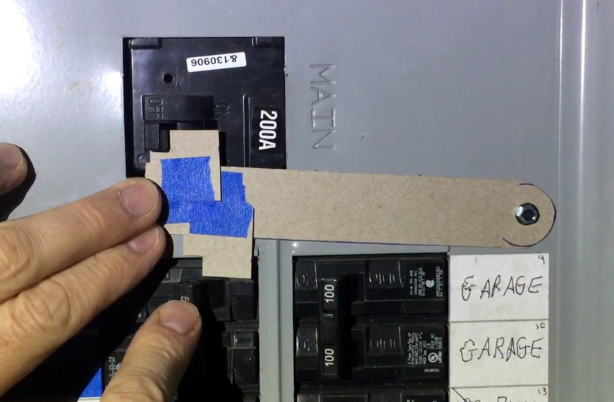
The hardest part of this project is designing the template. It needs to be carefully shaped so its resting position prevents the generator’s breaker from being switched on under normal circumstances, but once the main is turned off and out of the way, you should be able to lift it up and have the clearance to flip the lower breaker. Spending some quality time at the breaker box with tape and a few pieces of cardboard is going to be the easiest way of finding the proper shape.

Making a template with thin cardboard.

In the video after the break, [HowToLou] demonstrates the ideal shape for his particular application, which should help you get your mind wrapped around the idea. There are a lot of variables involved, not least of which the size and placement of the breakers, so taking the time to get the template right is critical.

Once you have the shape, you could really make the plate however you want. [HowToLou] cuts his by hand out of a piece of thin aluminum, but you could certainly 3D print it or even CNC it out of a thicker piece of metal. The important thing is that its stiff enough that somebody can’t just bend it out of the way if they’re fumbling around with it in the dark.

It probably goes without saying that a homemade interlock isn’t going to be up to code, but even if you don’t have any inspectors sniffing around your electrical panel, it’s a sensible precaution to have something like this installed. The middle of winter is a bad time to realize you don’t have any way to safely power your home when the grid goes down, so the key is getting something like this ready to go before you actually need it.

source https://hackaday.com/2021/02/22/how-to-design-a-custom-generator-interlock-plate/

DIY Neuroscience Hack Chat

Join us on Wednesday, February 24 at noon Pacific for the DIY Neuroscience Hack Chat with Timothy Marzullo!

Watch a film about a mad scientist from the golden age of Hollywood and chances are good that among the other set pieces, you’ll see human brains floating in jars of cloudy fluid wired up to electrodes and fancy machines. It’s all made up, of course, but tropes work because they’re based on a kernel of truth, and we in the audience know that our brains and the other parts of our nervous system do indeed work on electricity. Or more precisely, excitable tissues in our nervous systems pass electrochemical signals between themselves as waves of potential across cell membranes.

Studying this electrical world locked away inside our heads is a challenging, but by no means impossible, pursuit. Usable signals can be picked up, amplified, digitized, and recorded to help us understand what’s going on when we think, feel, move, sleep, wake, or just be. Neuroscience has made tremendous strides looking at these signals, but the equipment to do so has largely remained the province of large universities and teaching hospitals with ample budgets, leaving the amateur neuroscientist out of luck.

Tim Marzullo, co-founder of Backyard Brains, is looking to change all that. While working on his Ph.D. in neuroscience at the University of Michigan, he and Greg Gage looked for ways to make the tools of neuroscience research affordable to everyone. The result is the Neuron SpikerBox, a low-cost bioamplifier that can tap into the “spikes” of action potential in live neurons. Open-source tools like these have helped educators bring neuroscience experiments to STEM students, and even helped other scientists set up novel, low-cost experiments.

Tim will join us on the Hack Chat to talk about doing DIY neuroscience and designing the instruments that make it possible. Bring your “mad scientist” questions as we push back the veil of ignorance on how our brains work, one neuron at a time.

join-hack-chatOur Hack Chats are live community events in the Hackaday.io Hack Chat group messaging. This week we’ll be sitting down on Wednesday, February 24 at 12:00 PM Pacific time (UTC-8). If time zones have you tied up, we have a handy time zone converter.

Click that speech bubble to the right, and you’ll be taken directly to the Hack Chat group on Hackaday.io. You don’t have to wait until Wednesday; join whenever you want and you can see what the community is talking about.


source https://hackaday.com/2021/02/22/diy-neuroscience-hack-chat/

Improving Cheap Ball Screws

Most 3D printers use leadscrews for at least one axis. These are simple devices that are essentially a steel screw thread and a brass nut that travels on it. However, for maximum precision, you’d like to use a ball screw. These are usually very expensive but have many advantages over a leadscrew. [MirageC] found cheaper ball screws but, since they were inexpensive, they had certain limitations. He designed a simple device that improves the performance of these cheap ball screws.

Superficially, a ball screw looks like a leadscrew with an odd-looking thread. However, the nut is very different. Inside the nut are ball bearings that fit in the grooves and allows the nut to spin around with much less friction. A special path collects the ball bearings and recirculates them to the other side of the nut. In general, ball screws are very durable, can handle higher loads and higher speeds, and require less maintenance. Unlike leadscrews, they are more expensive and are usually quite rigid. They are also a bit noisier, though.

Ball screws are rated C0 to C10 precision where C10 is the least accurate and the price goes up — way up — with accuracy. [MirageC] shows how cheaper ball screws can be rolled instead of precision ground. These screws are cheaper and harder, but exhibit more runout than a precision screw.

This runout caused wobble during 3D printing that was immediately obvious on the prints. Using a machinist’s dial gauge, [MirageC] found the screws were not straight at all and that even a relatively poor C7 ball screw would be more precise.

The solution? A clever arrangement of 3D printed parts. ball bearings, and magnets. The device allows the nut to move laterally without transmitting it to the print bed. It is a clever design and seems to work well.

If you want to learn more about ball screws, we can help. Although the accompanying video is dead, Mitsumi had some very good information to share about them, too.

source https://hackaday.com/2021/02/22/improving-cheap-ball-screws/

A Brief History of Viruses

It was around the year 1590 when mankind figured out how to use optical lenses to bring into sight things smaller than the natural eye can observe. With the invention of the microscope, a new and unexplored world was discovered. It will likely be of great surprise to the reader that scientists of the time did not believe that within this new microscopic realm lay the source of sickness and disease. Most would still hold on to a belief of what was known as Miasma theory, which dates back to the Roman Empire. This theory states that the source of disease was contaminated air through decomposing organic materials. It wouldn’t be until the 1850’s that a man by the name of Louis Pasteur, from whom we get “pasteurization”, would promote Germ Theory into the spotlight of the sciences.

Louis Pasteur experimenting in his lab.
Louis Pasteur. Source

Pasteur, considered by many as the father of microbiology, would go on to assist fellow biologist Charles Chameberland in the invention of the aptly named Pasteur Chamberland filter — a porcelain filter with a pore size between 100 and 1000 nanometers. This was small enough to filter out the microscopic bacteria and cells known at that time from a liquid suspension, leaving behind a supply of uncontaminated water. But like so many other early scientific instrumentation inventions it would lead to the discovery of something unexpected. In this case, a world far smaller than 100 nanometers… and add yet another dimension to the ever-shrinking world of the microscopic.

This is when we began to learn about viruses.

Discovery of the Virus and the Vaccine

The word “virus” stems from the Latin phrase “slimy fluid“. In 1898, a man by the name of Martinus Beijerinck passed a solution containing a still unknown infectious agent that targeted tobacco plants through a Pasteur Chamberland filter. The purified solution was applied to a healthy tobacco plant and to his great surprise the plant became infected. He concluded that the infectious agent was unfilterable, and took an even further leap to describe the infectious agent as a “living liquid”.

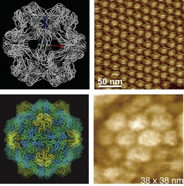
Microscopic Virus
The Brome Mosaic virus easily passed through filters. Source

In that same year, a pair of German scientists, Friedrich Loeffler and Paul Frosch, performed the same experiment which returned the same results with what we now know as Foot-and-Mouth Disease (FMDV) in livestock. They, however, did not agree with Beijerinck’s conclusion of the infectious agent being a living liquid. But instead believed it to be a particulate that was smaller than the porcelain filter pore size. They pushed forward with their belief by heating the filter element to “destroy the agent’s infectivity”, though it was not clear to them as to how heat destroyed it. Nevertheless, they were successful in creating an FMDV vaccine for cows and sheep from the infectious solution that was passed through the heated filter, which put more precedence on understanding a virus as an ultrascopic living particulate, and not a living liquid.

It should be noted that the smallpox vaccine was widely used at this time, though no one had any understanding of how it worked or what it even was. Indeed, the term vaccine is derived from the Latin word vacca, which translates directly to cow.  This odd relationship owes its history to the somewhat accidental discovery that milkmaids who often contracted a very mild disease called cowpox did not get infected with the much more severe smallpox disease. In 1796, a cruel experiment was performed by a man named Edward Jenner. He took puss from a cowpox blister and purposely infected a young boy. Once the boy recovered, he repeated the process with smallpox and found that the boy did not get the disease. Jenner’s vaccination technique would not only go on to save millions of lives from smallpox; it would be used to vaccinate people from several other diseases, including polio and yellow fever.

The Birth of Molecular Biology

COVID-19 virus spikes
A molecular view of the COVID-19 protein “spikes”. Source

The next few decades would identify hundreds of viruses of all shapes and sizes, and along with them various types of vaccines. But it was the study of exactly what these viruses were and how the vaccines actually worked that would give rise to a revolutionary new science — molecular biology.

New technologies such as electron microscopy, along with other advances in scientific understandings would show that viruses are some of the smallest lifeforms on earth. It could even be argued that they’re not alive at all… an debate that carries on to this day. Our own [Dan Maloney] has written several articles on the details of how viruses and our immune system work at a molecular level. And the clever ways we try to stop viruses. However, there is still much to be learned.

Understanding viruses at the molecular level presents a very real modern day challenge. Despite the full power, wealth, and knowledge of our modern civilization, a tiny packet of RNA enclosed in a fatty drop continues to wreak havoc on our world. The COVID-19 virus has in some shape, form, or fashion effected every single human being on earth. Those viruses once invisible to us now stand before our very eyes in full view, and yet we have suffered terrible losses to this one. Our best tool is a breakthrough barely 30 years old — our ability to tailor messenger RNA (mRNA) a targeted purpose — has very quickly led to a viable vaccine. There is no doubt in my mind that eventually this virus will succumb to the might of human ingenuity that has been unlocked by more than a century of cumulative scientific knowledge.

source https://hackaday.com/2021/02/22/a-brief-history-of-viruses/

A Brief History of Viruses

It was around the year 1590 when mankind figured out how to use optical lenses to bring into sight things smaller than the natural eye can observe. With the invention of the microscope, a new and unexplored world was discovered. It will likely be of great surprise to the reader that scientists of the time did not believe that within this new microscopic realm lay the source of sickness and disease. Most would still hold on to a belief of what was known as Miasma theory, which dates back to the Roman Empire. This theory states that the source of disease was contaminated air through decomposing organic materials. It wouldn’t be until the 1850’s that a man by the name of Louis Pasteur, from whom we get “pasteurization”, would promote Germ Theory into the spotlight of the sciences.

Louis Pasteur experimenting in his lab.
Louis Pasteur. Source

Pasteur, considered by many as the father of microbiology, would go on to assist fellow biologist Charles Chameberland in the invention of the aptly named Pasteur Chamberland filter — a porcelain filter with a pore size between 100 and 1000 nanometers. This was small enough to filter out the microscopic bacteria and cells known at that time from a liquid suspension, leaving behind a supply of uncontaminated water. But like so many other early scientific instrumentation inventions it would lead to the discovery of something unexpected. In this case, a world far smaller than 100 nanometers… and add yet another dimension to the ever-shrinking world of the microscopic.

This is when we began to learn about viruses.

Discovery of the Virus and the Vaccine

The word “virus” stems from the Latin phrase “slimy fluid“. In 1898, a man by the name of Martinus Beijerinck passed a solution containing a still unknown infectious agent that targeted tobacco plants through a Pasteur Chamberland filter. The purified solution was applied to a healthy tobacco plant and to his great surprise the plant became infected. He concluded that the infectious agent was unfilterable, and took an even further leap to describe the infectious agent as a “living liquid”.

Microscopic Virus
The Brome Mosaic virus easily passed through filters. Source

In that same year, a pair of German scientists, Friedrich Loeffler and Paul Frosch, performed the same experiment which returned the same results with what we now know as Foot-and-Mouth Disease (FMDV) in livestock. They, however, did not agree with Beijerinck’s conclusion of the infectious agent being a living liquid. But instead believed it to be a particulate that was smaller than the porcelain filter pore size. They pushed forward with their belief by heating the filter element to “destroy the agent’s infectivity”, though it was not clear to them as to how heat destroyed it. Nevertheless, they were successful in creating an FMDV vaccine for cows and sheep from the infectious solution that was passed through the heated filter, which put more precedence on understanding a virus as an ultrascopic living particulate, and not a living liquid.

It should be noted that the smallpox vaccine was widely used at this time, though no one had any understanding of how it worked or what it even was. Indeed, the term vaccine is derived from the Latin word vacca, which translates directly to cow.  This odd relationship owes its history to the somewhat accidental discovery that milkmaids who often contracted a very mild disease called cowpox did not get infected with the much more severe smallpox disease. In 1796, a cruel experiment was performed by a man named Edward Jenner. He took puss from a cowpox blister and purposely infected a young boy. Once the boy recovered, he repeated the process with smallpox and found that the boy did not get the disease. Jenner’s vaccination technique would not only go on to save millions of lives from smallpox; it would be used to vaccinate people from several other diseases, including polio and yellow fever.

The Birth of Molecular Biology

COVID-19 virus spikes
A molecular view of the COVID-19 protein “spikes”. Source

The next few decades would identify hundreds of viruses of all shapes and sizes, and along with them various types of vaccines. But it was the study of exactly what these viruses were and how the vaccines actually worked that would give rise to a revolutionary new science — molecular biology.

New technologies such as electron microscopy, along with other advances in scientific understandings would show that viruses are some of the smallest lifeforms on earth. It could even be argued that they’re not alive at all… an debate that carries on to this day. Our own [Dan Maloney] has written several articles on the details of how viruses and our immune system work at a molecular level. And the clever ways we try to stop viruses. However, there is still much to be learned.

Understanding viruses at the molecular level presents a very real modern day challenge. Despite the full power, wealth, and knowledge of our modern civilization, a tiny packet of RNA enclosed in a fatty drop continues to wreak havoc on our world. The COVID-19 virus has in some shape, form, or fashion effected every single human being on earth. Those viruses once invisible to us now stand before our very eyes in full view, and yet we have suffered terrible losses to this one. Our best tool is a breakthrough barely 30 years old — our ability to tailor messenger RNA (mRNA) a targeted purpose — has very quickly led to a viable vaccine. There is no doubt in my mind that eventually this virus will succumb to the might of human ingenuity that has been unlocked by more than a century of cumulative scientific knowledge.

source https://hackaday.com/2021/02/22/a-brief-history-of-viruses/

A Brief History of Viruses

It was around the year 1590 when mankind figured out how to use optical lenses to bring into sight things smaller than the natural eye can observe. With the invention of the microscope, a new and unexplored world was discovered. It will likely be of great surprise to the reader that scientists of the time did not believe that within this new microscopic realm lay the source of sickness and disease. Most would still hold on to a belief of what was known as Miasma theory, which dates back to the Roman Empire. This theory states that the source of disease was contaminated air through decomposing organic materials. It wouldn’t be until the 1850’s that a man by the name of Louis Pasteur, from whom we get “pasteurization”, would promote Germ Theory into the spotlight of the sciences.

Louis Pasteur experimenting in his lab.
Louis Pasteur. Source

Pasteur, considered by many as the father of microbiology, would go on to assist fellow biologist Charles Chameberland in the invention of the aptly named Pasteur Chamberland filter — a porcelain filter with a pore size between 100 and 1000 nanometers. This was small enough to filter out the microscopic bacteria and cells known at that time from a liquid suspension, leaving behind a supply of uncontaminated water. But like so many other early scientific instrumentation inventions it would lead to the discovery of something unexpected. In this case, a world far smaller than 100 nanometers… and add yet another dimension to the ever-shrinking world of the microscopic.

This is when we began to learn about viruses.

Discovery of the Virus and the Vaccine

The word “virus” stems from the Latin phrase “slimy fluid“. In 1898, a man by the name of Martinus Beijerinck passed a solution containing a still unknown infectious agent that targeted tobacco plants through a Pasteur Chamberland filter. The purified solution was applied to a healthy tobacco plant and to his great surprise the plant became infected. He concluded that the infectious agent was unfilterable, and took an even further leap to describe the infectious agent as a “living liquid”.

Microscopic Virus
The Brome Mosaic virus easily passed through filters. Source

In that same year, a pair of German scientists, Friedrich Loeffler and Paul Frosch, performed the same experiment which returned the same results with what we now know as Foot-and-Mouth Disease (FMDV) in livestock. They, however, did not agree with Beijerinck’s conclusion of the infectious agent being a living liquid. But instead believed it to be a particulate that was smaller than the porcelain filter pore size. They pushed forward with their belief by heating the filter element to “destroy the agent’s infectivity”, though it was not clear to them as to how heat destroyed it. Nevertheless, they were successful in creating an FMDV vaccine for cows and sheep from the infectious solution that was passed through the heated filter, which put more precedence on understanding a virus as an ultrascopic living particulate, and not a living liquid.

It should be noted that the smallpox vaccine was widely used at this time, though no one had any understanding of how it worked or what it even was. Indeed, the term vaccine is derived from the Latin word vacca, which translates directly to cow.  This odd relationship owes its history to the somewhat accidental discovery that milkmaids who often contracted a very mild disease called cowpox did not get infected with the much more severe smallpox disease. In 1796, a cruel experiment was performed by a man named Edward Jenner. He took puss from a cowpox blister and purposely infected a young boy. Once the boy recovered, he repeated the process with smallpox and found that the boy did not get the disease. Jenner’s vaccination technique would not only go on to save millions of lives from smallpox; it would be used to vaccinate people from several other diseases, including polio and yellow fever.

The Birth of Molecular Biology

COVID-19 virus spikes
A molecular view of the COVID-19 protein “spikes”. Source

The next few decades would identify hundreds of viruses of all shapes and sizes, and along with them various types of vaccines. But it was the study of exactly what these viruses were and how the vaccines actually worked that would give rise to a revolutionary new science — molecular biology.

New technologies such as electron microscopy, along with other advances in scientific understandings would show that viruses are some of the smallest lifeforms on earth. It could even be argued that they’re not alive at all… an debate that carries on to this day. Our own [Dan Maloney] has written several articles on the details of how viruses and our immune system work at a molecular level. And the clever ways we try to stop viruses. However, there is still much to be learned.

Understanding viruses at the molecular level presents a very real modern day challenge. Despite the full power, wealth, and knowledge of our modern civilization, a tiny packet of RNA enclosed in a fatty drop continues to wreak havoc on our world. The COVID-19 virus has in some shape, form, or fashion effected every single human being on earth. Those viruses once invisible to us now stand before our very eyes in full view, and yet we have suffered terrible losses to this one. Our best tool is a breakthrough barely 30 years old — our ability to tailor messenger RNA (mRNA) a targeted purpose — has very quickly led to a viable vaccine. There is no doubt in my mind that eventually this virus will succumb to the might of human ingenuity that has been unlocked by more than a century of cumulative scientific knowledge.

source https://hackaday.com/2021/02/22/a-brief-history-of-viruses/

Slick Web Oscilloscope is Ready in a Flash (Literally)

A bench oscilloscope is one of the most invaluable tools in the hardware hacker’s arsenal, but even the slimmest digital models are a bit large to be part of your everyday electronic carry. Sure you could throw one of those cheap pocket scopes in your bag, but what if there was an even easier way to take a peek at a few signals while you’re on the go?

For those who roam, the Arduino-web-oscilloscope project created by [David Buezas] is worth a close look. Using the Web Serial API built into recent versions of Google’s Chrome browser, this project allows you to pop open a software oscilloscope without installing anything locally. Whether it’s a public computer or that cheap Chromebook you keep around for emergencies, a valuable tool is just a few clicks away.

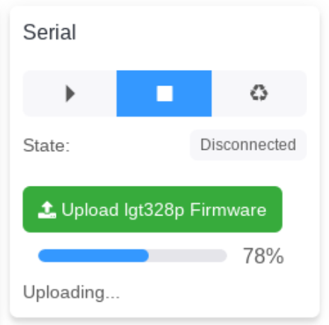
Flashing the MCU from the web interface.

Of course, there has to be some hardware involved. Despite what you might think given the name of the project, the code currently only supports the Logic Green LGT8F328P microcontroller. This cheap ATmega328P clone not only runs at 32 Mhz but according to [David], many operations can be done in fewer clock cycles than on the original 328P. In short it’s fast, and fast is good if you want more samples.

One of the best parts about this project is that a function to flash the firmware to the LGT8F328P is built right in the web interface. With the oscilloscope running in the browser, you just need to plug in a blank board, click the button to flash it, and start taking measurements. You could outfit a whole classroom or hackerspace with basic oscilloscopes in minutes, with a per-seat cost of just a few bucks.

Of course, there are some pretty hard limits on what you can realistically measure with this setup. For one thing, the board can’t handle anything higher than 5 volts. Even the cheapest oscilloscope kit is still going to be an upgrade, but the fact you can spin this up almost anywhere for the cost of a cheap MCU board makes it hard to complain about the results.

[Thanks to Bill for the tip.]

source https://hackaday.com/2021/02/22/slick-web-oscilloscope-is-ready-in-a-flash-literally/

Slick Web Oscilloscope is Ready in a Flash (Literally)

A bench oscilloscope is one of the most invaluable tools in the hardware hacker’s arsenal, but even the slimmest digital models are a bit large to be part of your everyday electronic carry. Sure you could throw one of those cheap pocket scopes in your bag, but what if there was an even easier way to take a peek at a few signals while you’re on the go?

For those who roam, the Arduino-web-oscilloscope project created by [David Buezas] is worth a close look. Using the Web Serial API built into recent versions of Google’s Chrome browser, this project allows you to pop open a software oscilloscope without installing anything locally. Whether it’s a public computer or that cheap Chromebook you keep around for emergencies, a valuable tool is just a few clicks away.

Flashing the MCU from the web interface.

Of course, there has to be some hardware involved. Despite what you might think given the name of the project, the code currently only supports the Logic Green LGT8F328P microcontroller. This cheap ATmega328P clone not only runs at 32 Mhz but according to [David], many operations can be done in fewer clock cycles than on the original 328P. In short it’s fast, and fast is good if you want more samples.

One of the best parts about this project is that a function to flash the firmware to the LGT8F328P is built right in the web interface. With the oscilloscope running in the browser, you just need to plug in a blank board, click the button to flash it, and start taking measurements. You could outfit a whole classroom or hackerspace with basic oscilloscopes in minutes, with a per-seat cost of just a few bucks.

Of course, there are some pretty hard limits on what you can realistically measure with this setup. For one thing, the board can’t handle anything higher than 5 volts. Even the cheapest oscilloscope kit is still going to be an upgrade, but the fact you can spin this up almost anywhere for the cost of a cheap MCU board makes it hard to complain about the results.

[Thanks to Bill for the tip.]

source https://hackaday.com/2021/02/22/slick-web-oscilloscope-is-ready-in-a-flash-literally/

Mastering The Tricky Job of Soldering SMA Connectors

There’s a satisfaction in watching someone else at work, particularly when they are demonstrating a solution to a soldering problem you have encountered in the past. SMA panel sockets have a particularly tiny solder bucket on their reverse, and since they often need to be soldered onto brass rod as part of microwave antenna construction they present a soldering challenge. [Andrew McNeil] is here to help, with a foolproof method of achieving a joint that is both electrically and mechanically sound.

The best connections to a solder bucket come when the wire connected to it nestles within its circular center. If this doesn’t happen and a blob of solder merely encapsulates both wire and bucket, the mechanical strength of the solder blob alone is not usually sufficient. The brass rod is wider than the bucket, so he takes us through carefully grinding it down to the right diameter for the bucket so it sits in place and can have the solder sweated into the gap. The result is very quick and simple, but has that essential satisfaction we mentioned earlier. It’s a small hack, but if you’ve ever soldered to a too-small RF connector you’ll understand. For more fun and games with RF connectors, take a look at our overview.

source https://hackaday.com/2021/02/22/mastering-the-tricky-job-of-soldering-sma-connectors/

How Tiny Can A Microcontroller Dev Board Be!

With innumerable microcontroller boards on the market it’s sure that there will be one for every conceivable application or user. Among them are some seriously tiny ones, but this wasn’t enough for [Alun Morris]. Wanting to see how small he could make an ATtiny board without a custom PCB, he took a SOIC-8 version of the popular minimalist processor and mated it to a 6mm by 8mm piece of 0.05″ prototyping board to create a device that is dwarfed by its connectors.

It’s an extremely simple circuit and hardly something that hasn’t been done before, but the value here is in the tricky soldering to make it rather than its novelty. The ATtiny402 and three passive SMD components are fitted on the smallest possible sliver of prototyping board to contain them, and the female headers and set of programming pins contribute far more to the volume of the device than the board itself. He also tried a side-on design with two smaller slivers of board before settling on the more conventional layout. The demonstration of the system in action seen in the video below the break is a magnetic flux detector, dwarfed by the 40-pin DIP Z80 it is sitting on.

A lot of boards claim to be tiny, but few are this small. This ESP32 is a more usual contender.

source https://hackaday.com/2021/02/21/how-tiny-can-a-microcontroller-dev-board-be/

Hackaday Links: February 21, 2021

Well, that was quite a show! The Perseverance rover arrived on Mars Thursday. Don’t tell the boss, but we spent the afternoon watching the coverage in the house on the big TV rather than slaving away in the office. It was worth it; for someone who grew up watching Jules Bergman and Frank Reynolds cover the Apollo program and the sometimes cheesy animations provided by NASA, the current coverage is pretty intense. A replay of the coverage is available – skip to about the 1:15:00 mark to avoid all the filler and fluff preceding the “Seven Minutes of Terror” main event. And not only did they safely deliver the package, but they absolutely nailed the landing. Perseverance is only about 2 km away from the ancient river delta it was sent to explore for signs of life. Nice shooting!

We’re also being treated to early images from Jezero crater. The first lowish-rez shots, from the fore and after hazard cameras, popped up just a few seconds after landing — the dust hadn’t even settled yet! Some wags complained about the image quality, apparently without thinking that the really good camera gear was stowed away and a couple of quick check images with engineering cameras would be a good idea while the rover still had contact with the Mars Reconnaissance Orbiter. Speaking of which, the HiRISE camera on the MRO managed to catch a stunning view of Perseverance’s descent under its parachute; the taking of that photo is an engineering feat all by itself. But all of this pales in comparison to a shot from one of the down-looking cameras in the descent stage, show Perseverance dangling from the skycrane just before touchdown. It was a really good day for engineering.

Would that our Earthly supply chains were as well-engineered as our Martian delivery systems. We’ve been hearing of issues all along the electronics supply chain, impacting a wide range of industries. Some of the problems are related to COVID-19, which has sickened workers staffing production and shipping lines. Some, though, like a fire at the AKM semiconductor plant in Japan, have introduced another pinch point in an already strained system. The fire was in October, but the impact on the manufacturer depending on the plant’s large-scale integration (LSI) and temperature-compensated crystal oscillators (TCXO) products is only just now being felt in the amateur radio market. The impact is likely not limited to that market, though — TCXOs pop up lots of gear, and the AKM plant made LSI chips for all kinds of applications.

What do you get when you combine a 3D-printer, a laser cutter, a CNC router, and a pick-and-place robot? Drones that fly right off the build plate, apparently. Aptly enough, it’s called LaserFactory, and it comes from MITs Computer Science and Artificial Intelligence Lab. By making different “bolt-on” tools for a laser cutter, the CSAIL team has combined multiple next-generation manufacturing methods in one platform. The video below shows a drone frame being laser-cut from acrylic, to which conductive silver paste is added by an extruder. A pick-and-place head puts components on the silver goo, solders everything together with a laser, and away it goes. They also show off ways of building up 3D structures, both by stacking up flat pieces of acrylic and by cutting and bending acrylic in situ. It’s obviously still just a proof of concept, but we really like the ideas presented here.

And finally, as proof that astronomers can both admit when they’re wrong and have fun while doing so, the most remote object in the Solar System has finally received a name. The object, a 400-km diameter object in a highly elliptical orbit that takes it from inside the orbit of Neptune to as far as 175 astronomical units (AU) from the Sun, is officially known as 2018 AG37. Having whimsically dubbed the previous furthest-known object “Farout,” astronomers kept with the theme and named its wayward sister “Farfarout.” Given the rapid gains in technology, chances are good that Farfarout won’t stay the Sun’s remotest outpost for long, and we fear the (Far)nout trend will eventually collapse under its own weight. We therefore modestly propose a more sensible naming scheme, perhaps something along the lines of “Farthest McFaraway.” It may not scale well, but at least it’s stupid.

source https://hackaday.com/2021/02/21/hackaday-links-february-21-2021/

Hackaday Links: February 21, 2021

Well, that was quite a show! The Perseverance rover arrived on Mars Thursday. Don’t tell the boss, but we spent the afternoon watching the coverage in the house on the big TV rather than slaving away in the office. It was worth it; for someone who grew up watching Jules Bergman and Frank Reynolds cover the Apollo program and the sometimes cheesy animations provided by NASA, the current coverage is pretty intense. A replay of the coverage is available – skip to about the 1:15:00 mark to avoid all the filler and fluff preceding the “Seven Minutes of Terror” main event. And not only did they safely deliver the package, but they absolutely nailed the landing. Perseverance is only about 2 km away from the ancient river delta it was sent to explore for signs of life. Nice shooting!

We’re also being treated to early images from Jezero crater. The first lowish-rez shots, from the fore and after hazard cameras, popped up just a few seconds after landing — the dust hadn’t even settled yet! Some wags complained about the image quality, apparently without thinking that the really good camera gear was stowed away and a couple of quick check images with engineering cameras would be a good idea while the rover still had contact with the Mars Reconnaissance Orbiter. Speaking of which, the HiRISE camera on the MRO managed to catch a stunning view of Perseverance’s descent under its parachute; the taking of that photo is an engineering feat all by itself. But all of this pales in comparison to a shot from one of the down-looking cameras in the descent stage, show Perseverance dangling from the skycrane just before touchdown. It was a really good day for engineering.

Would that our Earthly supply chains were as well-engineered as our Martian delivery systems. We’ve been hearing of issues all along the electronics supply chain, impacting a wide range of industries. Some of the problems are related to COVID-19, which has sickened workers staffing production and shipping lines. Some, though, like a fire at the AKM semiconductor plant in Japan, have introduced another pinch point in an already strained system. The fire was in October, but the impact on the manufacturer depending on the plant’s large-scale integration (LSI) and temperature-compensated crystal oscillators (TCXO) products is only just now being felt in the amateur radio market. The impact is likely not limited to that market, though — TCXOs pop up lots of gear, and the AKM plant made LSI chips for all kinds of applications.

What do you get when you combine a 3D-printer, a laser cutter, a CNC router, and a pick-and-place robot? Drones that fly right off the build plate, apparently. Aptly enough, it’s called LaserFactory, and it comes from MITs Computer Science and Artificial Intelligence Lab. By making different “bolt-on” tools for a laser cutter, the CSAIL team has combined multiple next-generation manufacturing methods in one platform. The video below shows a drone frame being laser-cut from acrylic, to which conductive silver paste is added by an extruder. A pick-and-place head puts components on the silver goo, solders everything together with a laser, and away it goes. They also show off ways of building up 3D structures, both by stacking up flat pieces of acrylic and by cutting and bending acrylic in situ. It’s obviously still just a proof of concept, but we really like the ideas presented here.

And finally, as proof that astronomers can both admit when they’re wrong and have fun while doing so, the most remote object in the Solar System has finally received a name. The object, a 400-km diameter object in a highly elliptical orbit that takes it from inside the orbit of Neptune to as far as 175 astronomical units (AU) from the Sun, is officially known as 2018 AG37. Having whimsically dubbed the previous furthest-known object “Farout,” astronomers kept with the theme and named its wayward sister “Farfarout.” Given the rapid gains in technology, chances are good that Farfarout won’t stay the Sun’s remotest outpost for long, and we fear the (Far)nout trend will eventually collapse under its own weight. We therefore modestly propose a more sensible naming scheme, perhaps something along the lines of “Farthest McFaraway.” It may not scale well, but at least it’s stupid.

source https://hackaday.com/2021/02/21/hackaday-links-february-21-2021/

Python Settles Bet About Best Strategy in Children’s Board Game

Simulating a tabletop game can be done for several reasons: to play the game digitally, to create computer opponent(s), or to prove someone wrong. In [Everett]’s case, he used Python to prove which adult was right about basic strategy in a children’s game.

[Everett]’s 5-year-old loves a simple game called Hoot Owl Hoot! in which players cooperatively work to move owls along a track to the safety of a nest. Player pieces move on spaces according to the matching colors drawn from a deck of cards. If a space is already occupied, a piece may jump ahead to the next available spot. The game has a bit more to it than that, but those are the important parts. After a few games, the adults in the room found themselves disagreeing about which strategy was optimal in this simple game.

It seemed to [Everett] that it was best to move pieces in the rear, keeping player pieces grouped together and maximizing the chance of free moves gained by jumping over occupied spaces. [Everett]’s wife countered that a “longest move” strategy was best, and one should always select whichever piece would benefit the most (i.e. move the furthest distance) from any given move. Which approach wins games in the fewest moves? This small Python script simulates the game enough to iteratively determine that the two strategies are quite close in results, but the “longest move” strategy does ultimately come out on top.

As far as simulations go, it’s no Tamagotchi Singularity and [Everett] admits that the simulation isn’t a completely accurate one. But since its only purpose is to compare whether “no stragglers” or “longest move” wins in fewer moves, shortcuts like using random color generation in place of drawing the colors from a deck shouldn’t make a big difference. Or would it? Regardless, we can agree that board games can be fitting metaphors for the human condition.

source https://hackaday.com/2021/02/21/python-settles-bet-about-best-strategy-in-childrens-board-game/

Inside an Oscillator with [Ken Shirriff]

We are always glad to see [Ken Shirriff] tear into something new and this month he’s looking inside a quartz oscillator module. Offhand, you’d think there’s not much to these. A slab of quartz and some sort of inverter, right? But as [Ken] mentions, “There’s more happening in the module than I expected…”

If you’ve ever wanted to decap devices, big hybrid modules like these are a good way to get started since you don’t need exotic chemicals to get at the insides. [Ken] managed to break the fragile crystal wafer on the way in. Inside was also a small CMOS IC die. Time to get out the microscope.

If you follow [Ken’s] blog, you know he’s no stranger to analyzing IC dice. The oscillator IC is a pretty standard Colpitts oscillator but it also provides a programmable divider and output drive.

The circuit uses some unusually configured capacitors. [Ken] takes the time to point out CMOS logic structures throughout. If you haven’t seen one of [Ken’s] deep dives before, before, it’s a great introduction.

You can learn more about crystal oscillator theory. We used some test equipment to characterize a crystal a few years ago.

source https://hackaday.com/2021/02/21/inside-an-oscillator-with-ken-shirriff/

Volumetric 3D Television Is Here!

Volumetric 3D displays that allow the viewing of full 3D images without special glasses are not unknown in our community, usually taking the form of either a 3D LED matrix or a spinning rotor either with an image projected onto it or holding an LED array. They are impressive projects, but they are often limited in what they can display. Pretty patterns and simple 3D models are all very well, but they are hardly 3D television. Thus we’re quite impressed with [Evlmnkey]’s bachelor’s degree project, which combines motion capture and a volumetric display for a genuine volumetric 3D closed-circuit television system.

Finding the details takes a bit of dredging through the Reddit thread, but the display is an off-the-shelf Adafruit single-sided LED matrix driven by an ESP32, all mounted on a motor with a pair of slip rings for power. Data is fed to the ESP via WiFi, with the PC responsible for grabbing the image sending it as uncompressed frames. There’s little detail on the 3D capture, but since he mentions a Kinect library we suspect that may be the source.

This is perhaps not the highest resolution TV you’ll ever have seen, indeed we’d liken it to the flickering 30 lines of 1930s mechanical TV, but it’s still a functioning volumetric 3D live CCTV system. If you’re interested by 3D displays, you might like to see our examination of the subject.

Thanks [nandkeypull] for the tip.

source https://hackaday.com/2021/02/21/volumetric-3d-television-is-here/

Apple II Talks to 3D Printer With a Little Modern help

Controlling most desktop 3D printers is as easy as sending them G-code commands over a serial connection. As you might expect, it takes a relatively quick machine to fire off the commands fast enough for a good-quality print. But what if you weren’t so picky? If speed isn’t a concern, what’s the practical limit on the type of computer you could use?

In an effort to answer that question, [Max Piantoni] set out to control his Ender 3 printer with an authentic Apple IIc. Things were made a bit easier by the fact that he really only wanted to use the printer as a 2D plotter, so he could ignore the third dimension in his code. All he needed to do was come up with a BASIC program that let him create some simple geometric artwork on the Apple and convert it into commands that could be sent out over the computer’s serial port.

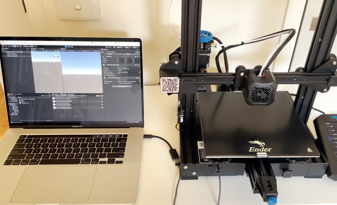
Unity controlling the Ender 3

Unfortunately, [Max] ran into something of a language barrier. While the Apple had no problem generating G-code the Ender’s controller would understand, both devices couldn’t agree on a data rate that worked for both of them. The 3D printer likes to zip along at 115,200 baud, while the Apple was plodding ahead at 300. Clearly, something would have to stand in as an interpreter.

The solution [Max] came up with certainly wouldn’t be our first choice, but there’s something to be said for working with what you know. He quickly whipped up a program in Unity on his Macbook that would accept incoming commands from the Apple II at 300 baud, build up a healthy buffer, and then send them off to the Ender 3. As you can see in the video after the break, this Mac-in-the-middle approach got these unlikely friends talking at last.

We’re reminded of a project from a few years back that aimed to build a fully functional 3D printer with 1980s technology. It was to be controlled by a Commodore PET from the 1980s, which also struggled to communicate quickly enough with the printer’s electronics. Bringing a modern laptop into the mix is probably cheating a bit, but at least it shows the concept is sound.

source https://hackaday.com/2021/02/21/apple-ii-talks-to-3d-printer-with-a-little-modern-help/