Judging by the tips we get, it seems like the popularity of word clocks has perhaps started falling off lately. But back at peak word clock, we were seeing dozens of designs, some better than others. This simple but classy word clock seems to benefit from all that prior art, making the design just about as simple as it can get while still looking great.
The main tool for [t0mg]’s build is a laser cutter, which is a great choice for keeping the design simple. The tricky part of word clocks is getting the “word search” matrix executed cleanly, and we’ve seen everything from laser-cut wood to inkjet prints, and even commercially produced PCBs, used for the job. [t0mg] opted instead to spray paint a piece of glass and etch away the characters with the laser, which results in superb text quality. Etching the underside of the glass also has the advantage of protecting the paint layer while giving the finished clock a glossy face that really looks nice. Under the template lie layers of MDF that hold the Neopixel strips and act as light guides, while an ESP32 and RTC perform timekeeping and LED-driving duties. [t0mg] finished off the clock with a nice web interface to set the clock, change the colors, and perform maintenance functions. The video below shows the software in use.
We really think this clock looks great, and for those with access to a laser cutter, it seems like a great way to go about building your own.
While ramen support might sound like a help desk for soup, it is actually a technique [GeoDroidJohn] uses to get easy-to-remove support structures on 3D prints. We saw the video below and we have to admit that it did remind us of a brick of uncooked ramen noodles.
We had to dig a little further to find out how he did it. We finally found a Reddit post that gives the recipe for Simplify 3D:
Nozzle diameter/2= layer height
Support material every other layer, 15% crossing at -45, and 45
5 dense layers at 90% 0 gap layers top or bottom.
We have to admit, we try to avoid support where we can, and where we can’t we just pick one of the stock Cura settings. It wasn’t entirely clear how — or even if — you could replicate this in slicers other than Simplify 3D. The layer height, of course, is a given. We think 15% support density with [-45, 45] in the “line directions” box might get partially there. Maybe someone who is an expert in Simplify and some other slicers can help translate.
In any event, it did make us think about experimenting with different support structures. We’ve played with Cura’s tree supports before this and liked them. So maybe the defaults aren’t always the best.
What do you know about the Nintendo Virtual Boy? Everybody knows that it was the console giant’s mid-90s foray into 3D graphics and VR, and that it was a commercial flop. Sickness and headache-inducing graphics are probably first to mind, and that’s it. But since most of us will never have handled one in real life, all we have on this legendary console is this Received Opinion. What was it Really like? [Rodrigo Copetti] has put up a detailed technical examination, and it reveals a machine well ahead of its time in more than just the market it was trying to create.
The first surprise is that this machine eschews the expected LCD screens that were the norm on handheld consoles of the day, instead using a persistence-of-vision display with a single vertical bar of LEDs facing a vibrating mirror through a lens system. He goes into significant detail on how this system worked, and in doing so gives us a new respect for the console.
The meat of this article lies though in a detailed look at the console’s architecture. The NEC V810 CPU was significantly more powerful than those in other portable consoles of the day, and we get a peek of how it and the custom silicon handled the graphics. The GPU had dual framebuffers for each display to ensure each frame could be delivered smoothly while the next one was being created.
Everything that can be said about the Virtual Boy in the marketplace has been done to death, leading to the received opinion we mentioned at the start of the article. This write-up provides new information on one of Nintendo’s rarer machines and casts it in an entirely new light.
There have been understandably few Virtual Boy projects that have made it to these pages. One that has, was a VGA interface for the console.
[Amen]’s Rockwell 920 calculator from the 70s was a very impressive piece of hardware for its time. It sported a 16-digit display, a printer, and it could run programs. It even had a magnetic card reader/writer that could be used to store programs and data externally. Seen through today’s eyes, it was less like a calculator and more like what we would call a single-board computer. They are also a window into another era, a time when many of the electrical design assumptions we take for granted hadn’t happened yet. When the time came to dig into what made the calculator tick, [Amen] had a lot of work to do just to get basic tools running.
For example, [amen]’s Blue Pill (an open-source, multipurpose test and measurement tool) is, on one hand, the perfect tool to snoop on the inner workings. However, those inner workings happen to use negative logic at -17 Volts, which means a logical zero is -17 V and a one is 0 V. Oh, and it uses an oddball clock rate, to boot. Since the Blue Pill doesn’t support -17 V negative logic (does anything?) a bit of custom work was needed to craft an interface. Once that was working, the Blue Pill was off to the races.
The unfamiliar elements didn’t end there. The pins on each IC, for example, are in a staggered layout quite unlike the DIP pattern most of us (and our tools, breadboards, and IC clips) are familiar with. As for the processor itself, [amen] has access to low-level documentation on Rockwell processors and instruction sets, but the timing diagrams are puzzling until one realizes the processor has two clock inputs at two different frequencies, resulting in what [amen] describes as four separate “clock phases”.
These design decisions were certainly made for good reasons at the time, and they even have a certain internal harmony to them, but it’s still a window into an era when the elements underpinning much of what we now have and work with had not yet happened.
Check out the video embedded below to see [amen] explain what it took to hook the Blue Pill up to a Rockwell 920. Also, if you’d like to see one of these vintage machines demonstrated in all its functioning glory, here’s a video of one being put through its paces.
On February 18th, the Perseverance rover safely touched down on the Martian surface. In the coming days and weeks, the wide array of instruments and scientific payloads tucked aboard the robotic explorer will spring to life; allowing us to learn more about the Red Planet. With a little luck, it may even bring us closer to determining if Mars once harbored life as we know it.
Among all of the pieces of equipment aboard the rover, one of the most intriguing must certainly be Ingenuity. This small helicopter will become the first true aircraft to take off and fly on another planet, and in a recent interview with IEEE Spectrum, operations lead [Tim Canham] shared some fascinating details about the vehicle and some of the unorthodox decisions that went into its design.
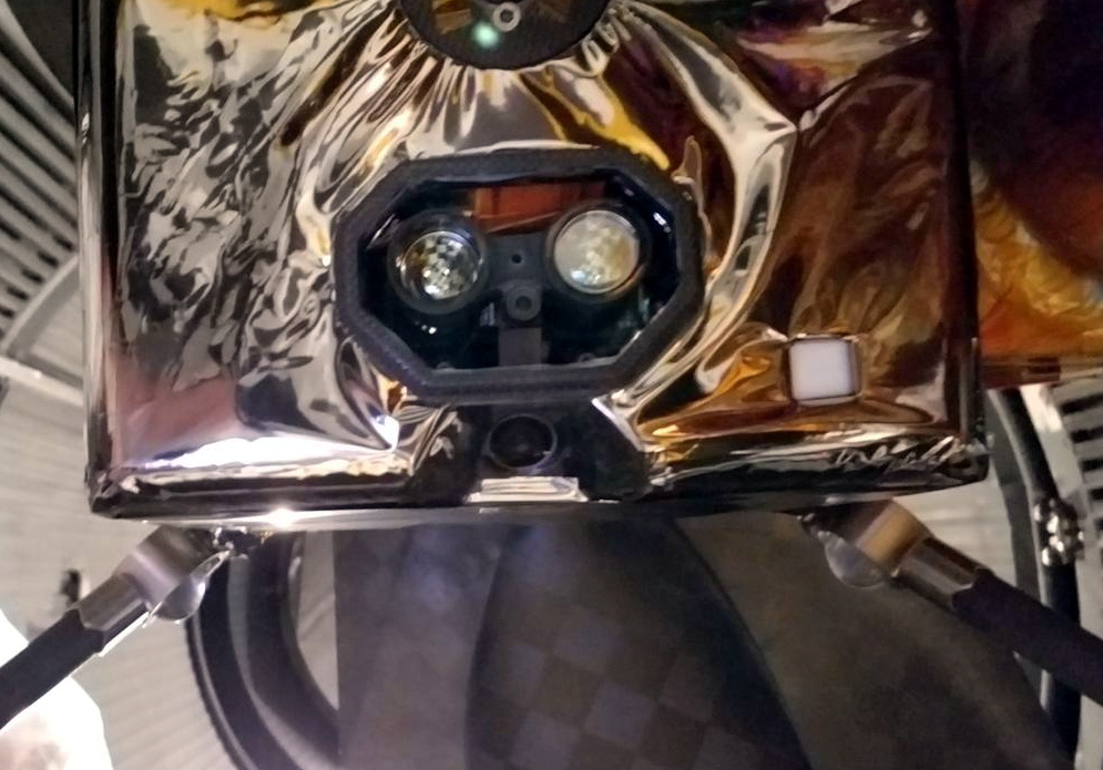
Ingenuity’s downward facing sensors.
[Tim] explains that, as a technology demonstrator, the team was allowed to take far more risks in developing Ingenuity than they would have been able to otherwise. Rather than sticking with legacy hardware and software, they were free to explore newer and less proven technology.
That included off-the-shelf consumer components, such as a laser altimeter purchased from SparkFun. It also means that the computational power packed into Ingenuity far exceeds that of Perseverance itself, though how well the helicopter’s smartphone-class Snapdragon 801 processor will handle the harsh Martian environment is yet to be seen.
On the software side, we also learn that Ingenuity is making extensive use of open source code. Not only is the onboard computer running Linux, but the vehicle is being controlled by an Apache 2.0 licensed framework developed by NASA’s Jet Propulsion Laboratory for CubeSats and other small spacecraft. The project is available on GitHub for anyone who wants it, and according to the changelog, the fixes and improvements required for the “Mars Helicopter Project” were merged in a few releases ago.
The fact that code currently ticking away on the surface of Mars can be downloaded and implemented into your own DIY project is a revelation that’s not lost on [Tim]. “It’s kind of an open-source victory because we’re flying an open-source operating system and an open-source flight software framework and flying commercial parts that you can buy off the shelf if you wanted to do this yourself someday.”
Of course, it took a whole lot more than some Python libraries and a handful of sensors from SparkFun to design and build the first space-going helicopter. But the fact that even a small slice of the technology inside of a project like Ingenuity is now available to the average hacker and maker is a huge step towards democratizing scientific research here on Earth.
On February 18th, the Perseverance rover safely touched down on the Martian surface. In the coming days and weeks, the wide array of instruments and scientific payloads tucked aboard the robotic explorer will spring to life; allowing us to learn more about the Red Planet. With a little luck, it may even bring us closer to determining if Mars once harbored life as we know it.
Among all of the pieces of equipment aboard the rover, one of the most intriguing must certainly be Ingenuity. This small helicopter will become the first true aircraft to take off and fly on another planet, and in a recent interview with IEEE Spectrum, operations lead [Tim Canham] shared some fascinating details about the vehicle and some of the unorthodox decisions that went into its design.
Ingenuity’s downward facing sensors.
[Tim] explains that, as a technology demonstrator, the team was allowed to take far more risks in developing Ingenuity than they would have been able to otherwise. Rather than sticking with legacy hardware and software, they were free to explore newer and less proven technology.
That included off-the-shelf consumer components, such as a laser altimeter purchased from SparkFun. It also means that the computational power packed into Ingenuity far exceeds that of Perseverance itself, though how well the helicopter’s smartphone-class Snapdragon 801 processor will handle the harsh Martian environment is yet to be seen.
On the software side, we also learn that Ingenuity is making extensive use of open source code. Not only is the onboard computer running Linux, but the vehicle is being controlled by an Apache 2.0 licensed framework developed by NASA’s Jet Propulsion Laboratory for CubeSats and other small spacecraft. The project is available on GitHub for anyone who wants it, and according to the changelog, the fixes and improvements required for the “Mars Helicopter Project” were merged in a few releases ago.
The fact that code currently ticking away on the surface of Mars can be downloaded and implemented into your own DIY project is a revelation that’s not lost on [Tim]. “It’s kind of an open-source victory because we’re flying an open-source operating system and an open-source flight software framework and flying commercial parts that you can buy off the shelf if you wanted to do this yourself someday.”
Of course, it took a whole lot more than some Python libraries and a handful of sensors from SparkFun to design and build the first space-going helicopter. But the fact that even a small slice of the technology inside of a project like Ingenuity is now available to the average hacker and maker is a huge step towards democratizing scientific research here on Earth.
On February 18th, the Perseverance rover safely touched down on the Martian surface. In the coming days and weeks, the wide array of instruments and scientific payloads tucked aboard the robotic explorer will spring to life; allowing us to learn more about the Red Planet. With a little luck, it may even bring us closer to determining if Mars once harbored life as we know it.
Among all of the pieces of equipment aboard the rover, one of the most intriguing must certainly be Ingenuity. This small helicopter will become the first true aircraft to take off and fly on another planet, and in a recent interview with IEEE Spectrum, operations lead [Tim Canham] shared some fascinating details about the vehicle and some of the unorthodox decisions that went into its design.
Ingenuity’s downward facing sensors.
[Tim] explains that, as a technology demonstrator, the team was allowed to take far more risks in developing Ingenuity than they would have been able to otherwise. Rather than sticking with legacy hardware and software, they were free to explore newer and less proven technology.
That included off-the-shelf consumer components, such as a laser altimeter purchased from SparkFun. It also means that the computational power packed into Ingenuity far exceeds that of Perseverance itself, though how well the helicopter’s smartphone-class Snapdragon 801 processor will handle the harsh Martian environment is yet to be seen.
On the software side, we also learn that Ingenuity is making extensive use of open source code. Not only is the onboard computer running Linux, but the vehicle is being controlled by an Apache 2.0 licensed framework developed by NASA’s Jet Propulsion Laboratory for CubeSats and other small spacecraft. The project is available on GitHub for anyone who wants it, and according to the changelog, the fixes and improvements required for the “Mars Helicopter Project” were merged in a few releases ago.
The fact that code currently ticking away on the surface of Mars can be downloaded and implemented into your own DIY project is a revelation that’s not lost on [Tim]. “It’s kind of an open-source victory because we’re flying an open-source operating system and an open-source flight software framework and flying commercial parts that you can buy off the shelf if you wanted to do this yourself someday.”
Of course, it took a whole lot more than some Python libraries and a handful of sensors from SparkFun to design and build the first space-going helicopter. But the fact that even a small slice of the technology inside of a project like Ingenuity is now available to the average hacker and maker is a huge step towards democratizing scientific research here on Earth.
If you want to hack around with the communication protocol that USB Power Delivery devices use to negotiate their power requirements with the upstream source, a tool like Google’s Twinkie really helps. With it you can sniff data off the line, analyze it, and even inject your own packets. Luckily for us, the search giant made the device open source so we can all have one of our own.
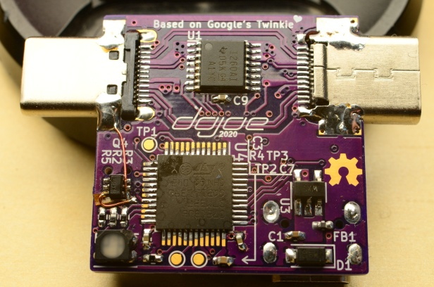
Unfortunately, as [dojoe] found out, the Twinkie isn’t particularly well suited for small-scale hobbyist manufacturing. So he came up with a revised design he calls Twonkie that replaces the six layer PCB with a much more reasonable four layer version that can be manufactured cheaply by OSHPark, and swaps out the BGA components with QFP alternatives you can hand solder.
That said, it’s still likely to be a challenging build for the home gamer. There’s quite a few 0402 passives on there, and while those are doable with an iron, it can certainly be tricky. To take some pressure off, [dojoe] says he tried to optimize the board layout as much as possible for hand assembly. He was even able to avoid needing hot air by straddling the PCB with USB-C mounts intended for vertical applications.
Given the current chip shortage, [dojoe] says the biggest problem might actually getting your hands on the STM32F072CB microcontroller at the Twonkie’s core. To that end, the board supports TQFP44 and QFN44 footprints, and you can even use a STM32F072C8 at the cost of some functionality. With a bit of luck, hopefully you can find a chip that will work in the parts bin.
Five years ago, I wrote a series on getting started with your own MQTT-based home information/automation network. Five years is a long while in Hackaday time. Back then, the ESP8266 was a lot newer, and the 8266 Arduino port wasn’t fully in shape yet, and the easiest software framework to get MQTT up and running was NodeMCU; so that’s what I used for the article series, and as a consequence a handful of devices around my house run minor modifications of that basic “hello world”, but doing useful stuff.
Since then, NodeMCU has changed a bunch of its libraries and the ESP32 has replaced the ESP8266 in my parts drawer. If you tried to run my code, you’d find that it won’t run on an ESP8266 without porting or compiling an old version of NodeMCU for yourself anyway, and it won’t run on an ESP32 at all. When [Chris Lott] tried to follow my guide, he discovered that Micropython is probably a better language choice in 2021. To minimize lines of code, I’d agree, although the Arduino and Espressif’s own native IDF have grown into the job just about as well. In short, anything but NodeMCU.
Built in an hour, survived for five years.
But my home automation system doesn’t care. Those little guys are running 24/7, flipping bits like it was still 2016. Thermometers, light sensors, and power meters haven’t changed much in five years, and although I’ve revamped the databasing, display, and user control a number of times since then, using a fixed communication transport protocol means that they’re still talking the same language. Indeed, even if NodeMCU is dead to me, the MQTT content of my original series is all still valid, and installing a broker on a Raspberry Pi has only become easier in the intervening five years.
So I’ve got a bunch of legacy code running within the walls of my own home, and it makes me nervous. If the devices fail, or maybe when they eventually fail, it’s not going to be “just flash another ESP8266 and replace it”, because even though I have some ancient NodeMCU binaries sitting around, I know when to throw in the towel. But there’s no good reason to pull them down and start reflashing either. Except that it makes me a little bit itchy, just knowing that there’s orphaned, dead-end code running all around me. Surrounding me. Staring deep into my hacker’s heart.
I know better than to tear down a running system, even though I could do it one device at a time, and each module would surely be a simple, independent fix; even though I’d love the excuse to play around with Micropython and its MQTT implementation on the ESP8266, or maybe even swap some of them out for ESP32s; even though these were all temporary quick hacks that have somehow served for five (5!) years. I certainly know better, right? (Right?)
This article is part of the Hackaday.com newsletter, delivered every seven days for each of the last 200+ weeks. It also includes our favorite articles from the last seven days that you can see on the web version of the newsletter.
Want this type of article to hit your inbox every Friday morning? You should sign up!
Five years ago, I wrote a series on getting started with your own MQTT-based home information/automation network. Five years is a long while in Hackaday time. Back then, the ESP8266 was a lot newer, and the 8266 Arduino port wasn’t fully in shape yet, and the easiest software framework to get MQTT up and running was NodeMCU; so that’s what I used for the article series, and as a consequence a handful of devices around my house run minor modifications of that basic “hello world”, but doing useful stuff.
Since then, NodeMCU has changed a bunch of its libraries and the ESP32 has replaced the ESP8266 in my parts drawer. If you tried to run my code, you’d find that it won’t run on an ESP8266 without porting or compiling an old version of NodeMCU for yourself anyway, and it won’t run on an ESP32 at all. When [Chris Lott] tried to follow my guide, he discovered that Micropython is probably a better language choice in 2021. To minimize lines of code, I’d agree, although the Arduino and Espressif’s own native IDF have grown into the job just about as well. In short, anything but NodeMCU.
Built in an hour, survived for five years.
But my home automation system doesn’t care. Those little guys are running 24/7, flipping bits like it was still 2016. Thermometers, light sensors, and power meters haven’t changed much in five years, and although I’ve revamped the databasing, display, and user control a number of times since then, using a fixed communication transport protocol means that they’re still talking the same language. Indeed, even if NodeMCU is dead to me, the MQTT content of my original series is all still valid, and installing a broker on a Raspberry Pi has only become easier in the intervening five years.
So I’ve got a bunch of legacy code running within the walls of my own home, and it makes me nervous. If the devices fail, or maybe when they eventually fail, it’s not going to be “just flash another ESP8266 and replace it”, because even though I have some ancient NodeMCU binaries sitting around, I know when to throw in the towel. But there’s no good reason to pull them down and start reflashing either. Except that it makes me a little bit itchy, just knowing that there’s orphaned, dead-end code running all around me. Surrounding me. Staring deep into my hacker’s heart.
I know better than to tear down a running system, even though I could do it one device at a time, and each module would surely be a simple, independent fix; even though I’d love the excuse to play around with Micropython and its MQTT implementation on the ESP8266, or maybe even swap some of them out for ESP32s; even though these were all temporary quick hacks that have somehow served for five (5!) years. I certainly know better, right? (Right?)
This article is part of the Hackaday.com newsletter, delivered every seven days for each of the last 200+ weeks. It also includes our favorite articles from the last seven days that you can see on the web version of the newsletter.
Want this type of article to hit your inbox every Friday morning? You should sign up!
Five years ago, I wrote a series on getting started with your own MQTT-based home information/automation network. Five years is a long while in Hackaday time. Back then, the ESP8266 was a lot newer, and the 8266 Arduino port wasn’t fully in shape yet, and the easiest software framework to get MQTT up and running was NodeMCU; so that’s what I used for the article series, and as a consequence a handful of devices around my house run minor modifications of that basic “hello world”, but doing useful stuff.
Since then, NodeMCU has changed a bunch of its libraries and the ESP32 has replaced the ESP8266 in my parts drawer. If you tried to run my code, you’d find that it won’t run on an ESP8266 without porting or compiling an old version of NodeMCU for yourself anyway, and it won’t run on an ESP32 at all. When [Chris Lott] tried to follow my guide, he discovered that Micropython is probably a better language choice in 2021. To minimize lines of code, I’d agree, although the Arduino and Espressif’s own native IDF have grown into the job just about as well. In short, anything but NodeMCU.
Built in an hour, survived for five years.
But my home automation system doesn’t care. Those little guys are running 24/7, flipping bits like it was still 2016. Thermometers, light sensors, and power meters haven’t changed much in five years, and although I’ve revamped the databasing, display, and user control a number of times since then, using a fixed communication transport protocol means that they’re still talking the same language. Indeed, even if NodeMCU is dead to me, the MQTT content of my original series is all still valid, and installing a broker on a Raspberry Pi has only become easier in the intervening five years.
So I’ve got a bunch of legacy code running within the walls of my own home, and it makes me nervous. If the devices fail, or maybe when they eventually fail, it’s not going to be “just flash another ESP8266 and replace it”, because even though I have some ancient NodeMCU binaries sitting around, I know when to throw in the towel. But there’s no good reason to pull them down and start reflashing either. Except that it makes me a little bit itchy, just knowing that there’s orphaned, dead-end code running all around me. Surrounding me. Staring deep into my hacker’s heart.
I know better than to tear down a running system, even though I could do it one device at a time, and each module would surely be a simple, independent fix; even though I’d love the excuse to play around with Micropython and its MQTT implementation on the ESP8266, or maybe even swap some of them out for ESP32s; even though these were all temporary quick hacks that have somehow served for five (5!) years. I certainly know better, right? (Right?)
This article is part of the Hackaday.com newsletter, delivered every seven days for each of the last 200+ weeks. It also includes our favorite articles from the last seven days that you can see on the web version of the newsletter.
Want this type of article to hit your inbox every Friday morning? You should sign up!
[Attoparsec] has been building intriguing musical projects on his YouTube channel for a while and his latest is no exception. Dubbed simply as “Node Module”, it is a rack-mounted hardware-based Markov chain beat sequencer. Traditionally Markov chains are software state machines that transition between states with given probabilities, often learned from a training corpus. That same principle has been applied to hardware beat sequencing.
Each Node Module has a trigger input, four outputs each with a potentiometer, and a trigger out. [Attoparsec] has a wonderful explanation of all the different parts and theories that make up the module at the start of his video, but the basic operation is that a trigger input comes in and the potentiometers are read to determine the probabilities of each output. One is randomly selected and fired. As you can imagine, there are loops and even dead-end nodes and for some musical pieces there is a certain number of beats expected, so a clever reset signal can be sent to pull the chain back to the initial starting state at a regular interval. The results are interesting to listen to and even better to imagine all the possibilities.
System76, a computer manufacturer known for selling machines which run Linux, recently unveiled the complete sources for their forthcoming Launch mechanical keyboard. Made with familiar tools, mass produced, and backed by a stable company it looks like the Launch will be a compelling entrant into the world of mechanical keyboards.
Back in March of 2020 System76 published a blog post about a new project they were embarking on; a mechanical keyboard with an unusual layout. At the time there was scant information available besides a summer 2021 target and little was heard until last week when they opened up access to the Launch repository. Everything should be recognizable if you’ve ever looked at the sources for a customized mechanical keyboard before, which is what gets our attention. Electrical sources are authored with KiCad and should be easy to tweak or fabricate. And mechanical components are provided in STEP files with mechanical drawings, presumably because they intend to actually manufacture these.
Feature wise all the usual hallmarks of a well designed keyboard are here. The Launch uses hostswap sockets to make it easy to install the usual Cherry MX compatible switch options, and includes per-key RGB backlighting courtesy of SK6805 LEDs. The ATmega32U4 runs the popular and extremely capable QMK firmware instead of something bespoke, so it should be easy to customize to the user’s desire.
System76 touts an unusual key layout, but if you’ve seen a 75% keyboard before it shouldn’t be too threatening (though we do wonder about that shrunken right shift). The most unusual feature is that it features a USB hub capable of full speed 10 gigabit USB 3.1 Gen 2 on two USB-C and two USB-A ports. It’s worth checking out the schematic to appreciate how much more complicated the hub design is than the rest of the keyboard, which is practically vestigial in comparison.
The remaining unknown is how the Launch integrates with Pop!_OS, System76’s awkwardly named remix of Ubuntu. They promise deep, compelling integration and we’re excited to see how that manifests.
System76, a computer manufacturer known for selling machines which run Linux, recently unveiled the complete sources for their forthcoming Launch mechanical keyboard. Made with familiar tools, mass produced, and backed by a stable company it looks like the Launch will be a compelling entrant into the world of mechanical keyboards.
Back in March of 2020 System76 published a blog post about a new project they were embarking on; a mechanical keyboard with an unusual layout. At the time there was scant information available besides a summer 2021 target and little was heard until last week when they opened up access to the Launch repository. Everything should be recognizable if you’ve ever looked at the sources for a customized mechanical keyboard before, which is what gets our attention. Electrical sources are authored with KiCad and should be easy to tweak or fabricate. And mechanical components are provided in STEP files with mechanical drawings, presumably because they intend to actually manufacture these.
Feature wise all the usual hallmarks of a well designed keyboard are here. The Launch uses hostswap sockets to make it easy to install the usual Cherry MX compatible switch options, and includes per-key RGB backlighting courtesy of SK6805 LEDs. The ATmega32U4 runs the popular and extremely capable QMK firmware instead of something bespoke, so it should be easy to customize to the user’s desire.
System76 touts an unusual key layout, but if you’ve seen a 75% keyboard before it shouldn’t be too threatening (though we do wonder about that shrunken right shift). The most unusual feature is that it features a USB hub capable of full speed 10 gigabit USB 3.1 Gen 2 on two USB-C and two USB-A ports. It’s worth checking out the schematic to appreciate how much more complicated the hub design is than the rest of the keyboard, which is practically vestigial in comparison.
The remaining unknown is how the Launch integrates with Pop!_OS, System76’s awkwardly named remix of Ubuntu. They promise deep, compelling integration and we’re excited to see how that manifests.
System76, a computer manufacturer known for selling machines which run Linux, recently unveiled the complete sources for their forthcoming Launch mechanical keyboard. Made with familiar tools, mass produced, and backed by a stable company it looks like the Launch will be a compelling entrant into the world of mechanical keyboards.
Back in March of 2020 System76 published a blog post about a new project they were embarking on; a mechanical keyboard with an unusual layout. At the time there was scant information available besides a summer 2021 target and little was heard until last week when they opened up access to the Launch repository. Everything should be recognizable if you’ve ever looked at the sources for a customized mechanical keyboard before, which is what gets our attention. Electrical sources are authored with KiCad and should be easy to tweak or fabricate. And mechanical components are provided in STEP files with mechanical drawings, presumably because they intend to actually manufacture these.
Feature wise all the usual hallmarks of a well designed keyboard are here. The Launch uses hostswap sockets to make it easy to install the usual Cherry MX compatible switch options, and includes per-key RGB backlighting courtesy of SK6805 LEDs. The ATmega32U4 runs the popular and extremely capable QMK firmware instead of something bespoke, so it should be easy to customize to the user’s desire.
System76 touts an unusual key layout, but if you’ve seen a 75% keyboard before it shouldn’t be too threatening (though we do wonder about that shrunken right shift). The most unusual feature is that it features a USB hub capable of full speed 10 gigabit USB 3.1 Gen 2 on two USB-C and two USB-A ports. It’s worth checking out the schematic to appreciate how much more complicated the hub design is than the rest of the keyboard, which is practically vestigial in comparison.
The remaining unknown is how the Launch integrates with Pop!_OS, System76’s awkwardly named remix of Ubuntu. They promise deep, compelling integration and we’re excited to see how that manifests.
Floppy disks are rapidly aging, and archivists are working hard to preserve what data is left. This has led to the development of advanced floppy controllers capable of capturing the raw flux data from disks. [bzotto] was experimenting with the Applesauce archival hardware, and had some fun with the tools.
The result is a highly esoteric Easter egg. [bzotto]’s Picturedsk tool takes a bitmap image as input, and imprints that image into the magnetic flux of the disk. Thus, when viewing a dump of the disk’s magnetic flux on an archival program, the hidden image will be revealed. As an extra treat, it also writes a 1-bit version of the image to track 0, along with a barebones Apple ][ program to display the image and implore the user to investigate further.
It’s a fun hack that we could imagine being used as part of a game at a retro computing con, when we get to go back to those of course. We’ve seen Applesauce used before, too. If you’ve got your own archival projects on the go, be sure to let us know!
Floppy disks are rapidly aging, and archivists are working hard to preserve what data is left. This has led to the development of advanced floppy controllers capable of capturing the raw flux data from disks. [bzotto] was experimenting with the Applesauce archival hardware, and had some fun with the tools.
The result is a highly esoteric Easter egg. [bzotto]’s Picturedsk tool takes a bitmap image as input, and imprints that image into the magnetic flux of the disk. Thus, when viewing a dump of the disk’s magnetic flux on an archival program, the hidden image will be revealed. As an extra treat, it also writes a 1-bit version of the image to track 0, along with a barebones Apple ][ program to display the image and implore the user to investigate further.
It’s a fun hack that we could imagine being used as part of a game at a retro computing con, when we get to go back to those of course. We’ve seen Applesauce used before, too. If you’ve got your own archival projects on the go, be sure to let us know!
Building antennas is a time-honored ham radio tradition. Shortwave antennas tend to be bulky but at VHF frequencies the antenna sizes are pretty manageable. [Fjkaan’s] 2 meter quadrifilar helicoidal antenna is a good example and the structure for it can be created with 3D printing combined with electrical conduit.
Many people, including [G4ILO] use PVC pipe for the structure, and that design inspired [Fjkaan]. Despite being a bit less substantial, the conduit seems to work well and it is easy to cut. The helical design is common for satellite work owing to its circular polarization and omnidirectional pattern.
A quadrifilar helicoidal antenna is really two antennas in one, with a phase difference of 90 degrees between the two. There are several ways this can be accomplished, but in practice, most of these antennas use different loop sizes for the two antennas. One loop will be a bit larger than the frequency of interest, and thus will be inductive. The other loop will be a little smaller, and therefore will exhibit capacitive reactance at the center frequency.
Even though the antennas are both reactive, in parallel, the reactances cancel leaving a nice resistive load to match the radio. The feed at the top, however, needs to balance through some form of balun or choke.
Measuring temperature turns out to be a fundamental function for a huge number of devices. You furnace’s programmable thermostat and digital clocks are obvious examples. If you just needed to know if a certain temperature is exceeded, you could use a bimetalic coil and a microswitch (or a mercury switch as was the method with old thermostats). But these days we want precision over a range of readings, so there are thermocouples that generate a small voltage, RTDs that change resistance with temperature, thermistors that also change resistance with temperature, infrared sensors, and vibrating wire sensors. The bandgap voltage of a semiconductor junction varies with temperature and that’s predictable and measurable, too. There are probably other methods too, some of which are probably pretty creative.
You can often think of creative ways to do any measurement. There’s an old joke about the smart-alec student in physics class. The question was how do you find the height of a building using a barometer. One answer was to drop the barometer from the top of the building and time how long it takes to hit the ground. Another answer — doubtlessly an engineering student — wanted to find the building engineer and offer to give them the barometer in exchange for the height of the building. By the same token, you could find the temperature by monitoring a standard thermometer with a camera or even a level sensor which is a topic for another post.
The point is, there are plenty of ways to measure anything, but in every case, you are converting what you want to know (temperature) into something you know how to measure like voltage, current, or physical position. Let’s take a look at how some of the most interesting temperature sensors accomplish this.
Thermocouples
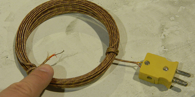
Thermocouples take advantage of something called the Seebeck effect. When two dissimilar metals form a junction and experience a temperature gradient, an electric potential forms. The key is that it is a gradient in temperature that makes the device work. Thermocouples have a hot junction and a cold junction. If you want to measure temperature, you need a reference junction. As an aside, the effect works in reverse — the Peltier effect — where passing current through a pair of junctions makes one side hot and the other one cold.
In the old days, you’d plunge the cold junction into a bucket of ice. Today, it is more likely that you’ll use another method to get the temperature of the cold junction and then compensate. There are chips that will do that for you, of course.
Why not just use the other method to start with? Thermocouples have several advantages. For one thing, you can measure up to a few thousand degrees with one. Since they are just two pieces of wire, they are robust and reliable. In hot or harsh environments, they are easy to manage and, usually, at the cold end you have a little nicer environment.
The downside is that the temperature reading is not linear. You’ll see different types of thermocouples and each type uses two different wire materials. The type tells you what calibration curve to use and, of course, you select the metal for the application you need. For example, a type J uses iron as one of the two wires and a type T uses copper.
The only other big consideration is how you run wires to the thermocouple. Since the device operates on a junction between two different types of wires, you have to be careful how you connect other wires to the device. Want to know more? [Bil Herd] did a deep dive into how to build a thermocouple amplifier.
Thermocouples that measure infrared from a distance are known as thermopiles. These are common in non-contact thermometers and passive IR (PIR) sensors. A PIR sensor detects the difference in temperature between two sensors and infers that something has changed in the field of view.
Resistance Devices
There are several different types of material that can exhibit temperature changes with resistance. The biggest factor is if the device has a positive or negative temperature coefficient. In other words, does the resistance go up or down in response to a change in temperature?
Most of these devices are also non-linear, but they are also inexpensive and easy to use. You can measure the resistance using any method you like. A common technique is to use the resistor as part of a voltage divider or bridge and measure the output voltage. However, if you’d rather not tie up an analog input, you can connect the resistor to a capacitor and measure the time it takes to charge.
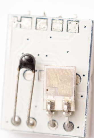
Thermistors are slightly different in construction from resistance temperature detectors, or RTDs. Usually, thermistors have less hysteresis and self-heating problems than the metal-based (often platinum) RTDs. However, in either case, you’ll have to measure resistance and fit it to a curve to get the real temperature.
Reading thermistors is a very common operation and there are a lot of tricks people have developed over the years. You can also spend math processing to get better curve fits, or do simple math and get less accuracy.
Semiconductor Junctions and Accidental Sensors
The bandgap voltage of semiconductor material varies predictably with temperature. If you ever get deep into solid state design, you’ll see the T term in the diode equation and all its manifestations. It is no surprise, then, that a lot of ICs use this property for sensing temperature.
Some chips are made to be temperature sensors. For example, the common LM34 and LM35 chips exploit this property with some additional circuits to provide a nice 10mV per degree (the LM34 measures Farhenheit and the LM35 measures Celcius). That makes them very easy to use.
Some chips, like the CPU in your PC, use the same method to measure internal temperature for reporting and thermal management. However, there are other ways non-temperature sensor ICs can measure temperature.
It turns out, almost all of our circuits are sensitive to temperature in some way. Measuring the internal clock of a CPU against an external reference can show temperature-induced changes.
Oddball Sensors
There are a multitude of other ways to measure temperature. For example, a vibrating wire sensor uses what amounts to a guitar string. The measurement involves exciting the string and detecting the frequency of vibration. As the supporting structure shrinks and expands with temperature changes, the tone of the string changes.
You can get an approximate temperature in degrees Fahrenheit by counting the number of chirps crickets make. Count the number of chirps in 15 seconds and then add 37. It wouldn’t surprise me if someone’s done that in some obscure instrument. [Kevin] in Terre Haute says the number is 40 in the video below, and not 37, but I guess it isn’t an exact science.
Of course, an increasingly common way to measure temperature is to use some form of smart sensor. A module or IC can use any of the methods we’ve talked about, convert it to engineering units, and send the data over something like an I2C bus. This is a level abstraction, but you still ought to understand the underlying benefits and limitations involved with the sensor you want to use.
While there may be more, there aren’t any other common techniques for measuring temperature. But there are still lots of sensors left to talk about in future articles.
Measuring temperature turns out to be a fundamental function for a huge number of devices. You furnace’s programmable thermostat and digital clocks are obvious examples. If you just needed to know if a certain temperature is exceeded, you could use a bimetalic coil and a microswitch (or a mercury switch as was the method with old thermostats). But these days we want precision over a range of readings, so there are thermocouples that generate a small voltage, RTDs that change resistance with temperature, thermistors that also change resistance with temperature, infrared sensors, and vibrating wire sensors. The bandgap voltage of a semiconductor junction varies with temperature and that’s predictable and measurable, too. There are probably other methods too, some of which are probably pretty creative.
You can often think of creative ways to do any measurement. There’s an old joke about the smart-alec student in physics class. The question was how do you find the height of a building using a barometer. One answer was to drop the barometer from the top of the building and time how long it takes to hit the ground. Another answer — doubtlessly an engineering student — wanted to find the building engineer and offer to give them the barometer in exchange for the height of the building. By the same token, you could find the temperature by monitoring a standard thermometer with a camera or even a level sensor which is a topic for another post.
The point is, there are plenty of ways to measure anything, but in every case, you are converting what you want to know (temperature) into something you know how to measure like voltage, current, or physical position. Let’s take a look at how some of the most interesting temperature sensors accomplish this.
Thermocouples
Thermocouples take advantage of something called the Seebeck effect. When two dissimilar metals form a junction and experience a temperature gradient, an electric potential forms. The key is that it is a gradient in temperature that makes the device work. Thermocouples have a hot junction and a cold junction. If you want to measure temperature, you need a reference junction. As an aside, the effect works in reverse — the Peltier effect — where passing current through a pair of junctions makes one side hot and the other one cold.
In the old days, you’d plunge the cold junction into a bucket of ice. Today, it is more likely that you’ll use another method to get the temperature of the cold junction and then compensate. There are chips that will do that for you, of course.
Why not just use the other method to start with? Thermocouples have several advantages. For one thing, you can measure up to a few thousand degrees with one. Since they are just two pieces of wire, they are robust and reliable. In hot or harsh environments, they are easy to manage and, usually, at the cold end you have a little nicer environment.
The downside is that the temperature reading is not linear. You’ll see different types of thermocouples and each type uses two different wire materials. The type tells you what calibration curve to use and, of course, you select the metal for the application you need. For example, a type J uses iron as one of the two wires and a type T uses copper.
The only other big consideration is how you run wires to the thermocouple. Since the device operates on a junction between two different types of wires, you have to be careful how you connect other wires to the device. Want to know more? [Bil Herd] did a deep dive into how to build a thermocouple amplifier.
Thermocouples that measure infrared from a distance are known as thermopiles. These are common in non-contact thermometers and passive IR (PIR) sensors. A PIR sensor detects the difference in temperature between two sensors and infers that something has changed in the field of view.
Resistance Devices
There are several different types of material that can exhibit temperature changes with resistance. The biggest factor is if the device has a positive or negative temperature coefficient. In other words, does the resistance go up or down in response to a change in temperature?
Most of these devices are also non-linear, but they are also inexpensive and easy to use. You can measure the resistance using any method you like. A common technique is to use the resistor as part of a voltage divider or bridge and measure the output voltage. However, if you’d rather not tie up an analog input, you can connect the resistor to a capacitor and measure the time it takes to charge.
Thermistors are slightly different in construction from resistance temperature detectors, or RTDs. Usually, thermistors have less hysteresis and self-heating problems than the metal-based (often platinum) RTDs. However, in either case, you’ll have to measure resistance and fit it to a curve to get the real temperature.
Reading thermistors is a very common operation and there are a lot of tricks people have developed over the years. You can also spend math processing to get better curve fits, or do simple math and get less accuracy.
Semiconductor Junctions and Accidental Sensors
The bandgap voltage of semiconductor material varies predictably with temperature. If you ever get deep into solid state design, you’ll see the T term in the diode equation and all its manifestations. It is no surprise, then, that a lot of ICs use this property for sensing temperature.
Some chips are made to be temperature sensors. For example, the common LM34 and LM35 chips exploit this property with some additional circuits to provide a nice 10mV per degree (the LM34 measures Farhenheit and the LM35 measures Celcius). That makes them very easy to use.
Some chips, like the CPU in your PC, use the same method to measure internal temperature for reporting and thermal management. However, there are other ways non-temperature sensor ICs can measure temperature.
It turns out, almost all of our circuits are sensitive to temperature in some way. Measuring the internal clock of a CPU against an external reference can show temperature-induced changes.
Oddball Sensors
There are a multitude of other ways to measure temperature. For example, a vibrating wire sensor uses what amounts to a guitar string. The measurement involves exciting the string and detecting the frequency of vibration. As the supporting structure shrinks and expands with temperature changes, the tone of the string changes.
You can get an approximate temperature in degrees Fahrenheit by counting the number of chirps crickets make. Count the number of chirps in 15 seconds and then add 37. It wouldn’t surprise me if someone’s done that in some obscure instrument. [Kevin] in Terre Haute says the number is 40 in the video below, and not 37, but I guess it isn’t an exact science.
Of course, an increasingly common way to measure temperature is to use some form of smart sensor. A module or IC can use any of the methods we’ve talked about, convert it to engineering units, and send the data over something like an I2C bus. This is a level abstraction, but you still ought to understand the underlying benefits and limitations involved with the sensor you want to use.
While there may be more, there aren’t any other common techniques for measuring temperature. But there are still lots of sensors left to talk about in future articles.
Hackaday editors Elliot Williams and Mike Szczys recount the coolest hacks from the past week. Most clocks keep time with a quartz crystal, but we discuss one that uses a tuning fork… like the kind you use to tune a piano. Ghidra is a powerful reverse engineering tool developed by the NSA that was recently put to good use changing an embedded thermometer display from Celsius to Fahrenheit. We talk turkey on the Texas power grid problems and Tesla’s eMMC failures. And of course there’s some room for nostalgia as we walk down memory lane with the BASIC programming language.
Take a look at the links below if you want to follow along, and as always, tell us what you think about this episode in the comments!
They say experience is the best teacher, and experience tells us they are right. When [Thomas Thiel] couldn’t find any resources about re-creating the groovy ‘caps of thocky old keebs like the Space Cadet and the C64 (or find any to buy), it was time for a little keycap experimentation.
These babies are printed in black resin and the inlay is made with white air-dry clay. After printing, they are sprayed with acrylic, and then [Thomas] works a generous amount of clay into the grooves and seals the whole thing with clear spray. [Thomas] soon figured out that the grooves had to be pretty deep for this to work right — at least 1 mm. And he had better luck thick fonts like Arial Black instead of thin fonts.
Of course, as [Thomas] mentions, you’re not restricted to white or even air-dry clay. You could go nuts with colored clay and make a retro-RGB clackable rainbow.
Let’s talk TCP. Specifically, how do the different TCP connections stay distinct, and how is a third party kept from interrupting a connection? One of the mechanisms that help accomplish this feat is the TCP sequence number. Each of the two endpoints of a TCP connection tracks an incrementing 32-bit number, corresponding to the bytes sent in the connection. It’s handy, because each side can use that value to track what parts of the data stream they have received. On missing packets, a message can be sent requesting bytes 7-15 to be resent, for instance.
Each side of the connection sets their own Initial Sequence Number (ISN), and it’s important that this number is unique, as collisions can cause stream confusion. That statement should make your security spidey sense tingle. If a collision can cause problems when it happens by chance, what can a hacker do with it intentionally? Potentially quite a bit. Knowing the current sequence number, as well as a couple other pieces of information, a third party can close a TCP stream or even inject data. The attack has been around for years, originally known as the Mitnick Attack. It was originally possible because TCP implementations used a simple counter to set the ISN. Once the security ramifications of this approach were understood, the major implementations moved to a random number generation for their ISNs.
Now to this week’s story: researchers at Forescout took the time to check 11 TCP/IP stacks for vulnerability to the old Mitnick Attack (PDF Whitepaper). Of the eleven embedded stacks texted, nine have serious weaknesses in their ISN generation. Most of the vulnerable implementations use a system time value as their ISN, while several use a predictable pseudorandom algorithm that can be easily reversed.
CVEs have been assigned, and vendors notified of “NUMBER:JACK”, Forescout’s name for the research. Most of the vulnerable software already has patches available. The problem with embedded systems is that they often never get security updates. The vulnerable network stacks are in devices like IP cameras, printers, and other “invisible” software. Time will tell if this attack shows up as part of a future IoT botnet.
Microsoft Patch Tuesday
Last week, Microsoft released their monthly round-up of patches, and there are a few interesting bugs. CVE-2021-24074 is a potential RCE resulting from improper handling of source routing packets. “Source routing” is one of the mostly forgotten IP options, though it does see some use in niche applications. Packets using this option are generally blocked by routers and security devices, making it essentially impossible to send such packets over the public internet. Windows clients also block these packets, but generate an ICMP response when such a packet is blocked. Reading between the lines, it seems that the vulnerability is triggered by the process of building the ICMP response. (Not a new problem) The patch is available, as is a simple workaround: simply dropping the incoming packets without a response.
Two other CVEs are potentially notable, though there is even less information available about them. CVE-2021-24078 is a wormable vulnerability in the Windows DNS server. Thankfully a server is only vulnerable if the DNS component has been turned on. The other is CVE-2021-26701, a rather vague “.NET Core Remote Code Execution Vulnerability”. It has a severity rating of critical, and Microsoft has indicated that the details are known in the wild.
Clubhouse Security Growing Pains
You may have heard that Clubhouse is the new social media flash-in-the-pan. Or, maybe it will stick around, who knows. If you haven’t looked into it, Clubhouse is something of an audio chatroom, where a celebrity or teacher can have a conversation with an audience. It’s still prelaunch, and there are already eight million downloads. As you might imagine, this success has put Clubhouse on the radar of security researchers, like the folks at Zerforschung. It seems that Clubhouse is built on the Agora.io platform, and the attack here is to talk directly to Agora.io rather than go through the Clubhouse app. The results? The attacker can leave the room, but maintain the connection to the backend. The username disappears, but still receives audio, and can even speak into the room. This breaks the ability to put a room into single-speaker mode and makes ejecting a user impossible.
Telegram Self-Destruct Messages
The problem? They aren’t actually destructed. [Dhiraj Mishra] did his research on the MacOS version of Telegram, and discovered that audio and video files sent in a self-destruct message is still available on the computer hard drive, even after the message timer has expired. For extra pwnage, this version of Telegram also stores the passcode in plaintext in some cases. Both issues have been fixed, so make sure you update if you use Telegram on MacOS.
More NPM Dependency Confusion
Last week we covered [Alex Birsan]’s dependency confusion attack, where a package can be uploaded to NPM that uses the name of a private package. If a company has their build system misconfigured, the public package can be pulled into the final build instead of the intended private package. Since [Alex] publicly announced the attack, nearly 300 such packages have been uploaded to NPM taking advantage of this technique. Note these are the packages that have been discovered, there are almost certainly more packages that are out there, but are yet to be discovered. [Alex] pointed out that some of these are likely other researchers aiming for bug bounties, but there might even be some legitimately malicious packages in the mix.
We’ll do our best to keep you up to date on these stories, and the rest that pop up each week, so stay tuned!
The great divide in terms of single board computers lies between those that can run some form of Linux-based distribution, and those that can not. For example the Raspberry Pi Zero is a Linux board, while the Raspberry Pi Pico’s RP2040 processor lacks the required hardware to run everybody’s favourite UNIX-like operating system. That’s not to say the new board from Cambridge can’t run any UNIX-like operating system though, as [David Given] shows us with his FUSIX port.
FUSIX is a UNIX-like operating system for less capable processors, more in the spirit of those original UNIXes than of a modern Linux-based distribution. It’s the work of the respected former Linux kernel developer and maintainer [Alan Cox], and consists of a kernel, a C compiler, and a set of core UNIX-like applications.
The RP2040 port maybe needs a little more work to be considered stable. For now, the multitasking support isn’t quite there and NAND flash support is broken, but it does have SD card support for a proper UNIX filesystem and the full set of core tools. Perhaps most interestingly, it only occupies a single core of the dual-core chip, leaving the possibility of the other core and those PIOs to be used for other purposes.
FUSIX has made the occasional appearance here over the years, but perhaps not as often as it should. If you’d like to learn a little more about the genesis of UNIX, we took a look in 2019.
Smart switches are fun, letting you control lights and appliances in your home over the web or even by voice if you’re so inclined. However, they can make day-to-day living more frustrating if they’re not set up properly with regards to your existing light switches. Thankfully, with some simple wiring, it’s possible to make everything play nice.
The method is demonstrated here by [MyHomeThings], in which an ESP8266 is used with a relay to create a basic smart switch. However, it’s wired up with a regular light switch in a typical “traveller” multiway switching scheme – just like when you have two traditional light switches controlling the same light at home. To make this work with the ESP8266, though, the microcontroller needs to be able to know the current state of the light. This is done by using a 240V to 3.3V power supply wired up in parallel with the light. When the light is on, the 3.3V supply is on. This supply feeds into a GPIO pin on the ESP8266, letting it know the light’s current state, and allowing it to set its output relay to the correct position as necessary.


 Feature wise all the usual hallmarks of a well designed keyboard are here. The Launch uses hostswap sockets to make it easy to install the usual Cherry MX compatible switch options, and includes per-key RGB backlighting courtesy of SK6805 LEDs. The ATmega32U4 runs the popular and extremely capable QMK firmware instead of something bespoke, so it should be easy to customize to the user’s desire.