For the last 11 years [Gunnar Kanold] has run the annual BASIC 10 Liner contest, and the rules for the 2021 edition are now available. There are four categories and each category has specific definitions of what constitutes a line. All entries must run on an 8-bit computer system that can be emulated.
The first three categories are for games but differ in the line length allowed. You can elect to compete with 80 character lines, 120 character lines, or 256 character lines. There’s also a category for demos, tools, and other applications that must constrain lines to 256 characters.
There are some common-sense rules, of course. You can’t load other programs or data from mass storage. You can’t use machine language or self-modifying code.
If you want to participate, you’ll need to submit your entry by March 27th and the results will be revealed on April 10th. If you need inspiration, look at some of the entries from last year, including Bomb Catcher, Ainvader, and Asteroid.
This is a good excuse to dust off your last retrocomputer project or replica. Seems like you’d want a BASIC that at least let you put multiple statements on a line, though, so probably don’t want to go back too far. Of course, you can always work on your favorite emulator, if you don’t have any hardware.
A trip to a supermarket is a rare luxury in a pandemic lockdown, but were I to cruise the aisles with my basket today I’d probably come away with a healthy pile of fruit and veg, a bit of meat and fish, and maybe some cheese. My shopping basket in 2031 though might have a few extras, and perhaps surprisingly some of them might be derived from insects. That’s a future made a little closer, by EU scientists declaring that farmed insect products are safe for humans and animals to eat.
Is meat consumption at this level sustainable? Our World In Data, CC BY 3.0.
We humans, like some of our fellow great ape cousins, are omnivores. We can eat anything, even if we might not always want to eat some things twice. As such, the diets of individual populations would in the past have varied hugely depending on the conditions that existed wherever they lived, giving us the ability to spread to almost anywhere on the planet — and we have.
Over the past few hundred years this need to subsist only on foods locally available has been marginalized by advances in agriculture. For those of us in developed countries, any foodstuff that takes our fancy can be ours for a trivial effort. This has meant an explosion of meat consumption as what was once a luxury food has become affordable to the masses, and in turn a corresponding agricultural expansion to meet demand that has placed intolerable stresses on ecosystems and is contributing significantly to global warming. It’s very clear that a mass conversion to veganism is unlikely to take place, so could farmed insects be the answer to our cravings for meat protein? It’s likely to be a tough sell to consumers, but it’s a subject that bears more examination.
Your Tasty, Nutritious, And Wriggy Friend!
Mealworms thrive on a diet of bran. Richard Chambers, (CC BY-SA 3.0).
Before any reader imagines chowing down on a creepy-crawly, it’s worth pointing out that the insects in question are likely not to be winged and legged adults staring back at would-be diners. Instead this is a story of an alternative protein source. These would almost certainly be larvae, the earlier stage in an insect lifecycle, dried and processed into other foodstuffs. So we may eventually eat a hamburger made from insect protein, for example.
The species most often named as a candidate is the mealworm, a beetle larva that is particularly easy to breed and which can be fed on readily available by-products of the cereal industry such as wheat bran. They are so straightforward to farm that it can be done at home, but even when scaled up to a commercial size facility they take up a fraction of the land and water resources required to farm the equivalent volume of livestock protein.
Don’t Get EU Scientists Started
The research paper from the EU scientists presents a detailed analysis of dried mealworm larvae, both whole and ground to a powder. For a non-food-scientist it’s an eye-opener how much detail they go into when doing this work, but as consumers it’s important for us to know that levels of bacteria, toxic heavy metals, or other poisonous compounds are kept in check. After a detailed examination of the farming procedure, they conclude that properly treated mealworm products fed on appropriate food that doesn’t contain any such nasties present no risks when eaten. Of the batches they tested, some had as high as 58.9% protein and 27.6% fat, with the majority of the rest being dietary fibre in the form of chitin. Anecdotal evidence from the online research for this piece suggests they have a pleasant flavour, described by some as slightly nutty.
I grew up surrounded by farmland on a heavy clay soil that had traditionally been dairy land but which transitioned over the 1970s and 1980s to arable with the introduction of more efficient soil management tillage techniques. Today it grows acres and acres of cereal crops, but they are by and large not destined for your plate. Instead huge swathes of countryside provide the feed for indoor livestock rearing operations, a vast quantity of land produces a surprisingly small quantity of foodstuff. Growing up in a British farming community as I did I enjoy eating good-quality meat, but it’s a view I’ve progressively arrived at over the years that farming it in this way is by no means the most efficient way to make food from land, nor is it the most environmentally friendly. I’d prefer to eat smaller quantities of higher-standard beef than expect daily to eat beef that has been intensively farmed in this manner. The prospect of farmed insect protein fed on the by-products from food crops grown on that land is thus one that can only be a positive step, and I welcome the EU move as an early step in our making that change. The question is, who will be first to pop a bug-burger in their shopping basket?
Nintendo’s Switch is perhaps most famous for blurring the lines between handheld consoles and those you plug into a TV. However, the tablet-esque device can also run Android if you’re so inclined, and it recently got an upgrade to version 10.
It’s an upgrade that brings many new features to the table, most of which you might consider must haves for regular use. The newer port brings support for USB Power Delivery, as well as deep sleep modes that enable the unit’s battery to last for several weeks. There’s also support for over-the-air updates which should ease ongoing maintenance, and improvements for Bluetooth compatibility and the touch screen as well.
Like most console hacks to run custom code, you’ve got to have the right hardware version with the right firmware, as Nintendo have been regularly iterating to try and lock out hacks where possible. The install has a few hurdles to jump through, but nothing too strenuous that would scare away the average Hackaday reader. Just be sure to not attempt this on a cherished console, as there’s always the chance that it all ends in tears. If you pull it off, you can then go about turning your Nintendo Switch into a networking switch. Net…tendo… Switch? Come up with a better pun in the comments.
Most of us have, or, would like to have a 3D printer, a laser engraver, and a CNC machine. However, if you think about it naively, these machines are not too different. You need some way to move in the XY plane and, usually, on the Z axis, as well.
Sure, people mount extruders on CNCs, or even lasers or Dremel tools on 3D printers. However, each machine has its own peculiarities. CNCs need rigidity. 3D printers should be fast. Laser engravers and CNCs don’t typically need much Z motion. So common sense would tell you that it would be tough to make a machine to do all three functions work well in each use case. [Stefan] thought that, too, until he got his hands on a Snapmaker 2.0.
As you can see in the video below, the machine uses different tool heads for each function. The motion system stays the same and, curiously, there are three identical linear motion modules, one for each axis.
In addition to the interchangeable heads, you also have to swap out the beds for different functions. That means changing over quickly isn’t really an option. [Stefan] reports there are 22 bolts to attach the heated bed for 3D printing, for example.
This isn’t cheap, of course, but if you had to buy all three devices, you’d probably spend as much, especially for all aluminum framed machines. There are some compromises. The linear modules use a leadscrew, which is an unusual choice on X and Y axis for 3D printers because they are slow and have more backlash than belts. However, [Stefan] found the quality was good, even though printing speed was slow and noisy.
Of course, when machining with the CNC head, the rigid leadscrews are a plus, even though the 50 W spindle isn’t going to replace a larger CNC machine. He was even able to machine some aluminum slowly. The laser head is modestly powered, but it does have a camera and low-tech air assist, although it isn’t a proper air system. Overall, [Stefan] felt like the machine was usable in all three phases. He did miss a prominent emergency stop button on the machine or even on the graphical user interface.
Overall, the Snapmaker looks like a good concept with some implementation problems, but no show stoppers. Like most amateur builds, the machine is basically a small CNC with accessories to do laser cutting and 3D printing. Could you build better? Maybe. But it wouldn’t be trivial to match the build quality and software integration of the device.
We’ve seen conversions of 3D printers to a laser or CNC more than once. Results vary, of course, but it is doable.
Most of us have, or, would like to have a 3D printer, a laser engraver, and a CNC machine. However, if you think about it naively, these machines are not too different. You need some way to move in the XY plane and, usually, on the Z axis, as well.
Sure, people mount extruders on CNCs, or even lasers or Dremel tools on 3D printers. However, each machine has its own peculiarities. CNCs need rigidity. 3D printers should be fast. Laser engravers and CNCs don’t typically need much Z motion. So common sense would tell you that it would be tough to make a machine to do all three functions work well in each use case. [Stefan] thought that, too, until he got his hands on a Snapmaker 2.0.
As you can see in the video below, the machine uses different tool heads for each function. The motion system stays the same and, curiously, there are three identical linear motion modules, one for each axis.
In addition to the interchangeable heads, you also have to swap out the beds for different functions. That means changing over quickly isn’t really an option. [Stefan] reports there are 22 bolts to attach the heated bed for 3D printing, for example.
This isn’t cheap, of course, but if you had to buy all three devices, you’d probably spend as much, especially for all aluminum framed machines. There are some compromises. The linear modules use a leadscrew, which is an unusual choice on X and Y axis for 3D printers because they are slow and have more backlash than belts. However, [Stefan] found the quality was good, even though printing speed was slow and noisy.
Of course, when machining with the CNC head, the rigid leadscrews are a plus, even though the 50 W spindle isn’t going to replace a larger CNC machine. He was even able to machine some aluminum slowly. The laser head is modestly powered, but it does have a camera and low-tech air assist, although it isn’t a proper air system. Overall, [Stefan] felt like the machine was usable in all three phases. He did miss a prominent emergency stop button on the machine or even on the graphical user interface.
Overall, the Snapmaker looks like a good concept with some implementation problems, but no show stoppers. Like most amateur builds, the machine is basically a small CNC with accessories to do laser cutting and 3D printing. Could you build better? Maybe. But it wouldn’t be trivial to match the build quality and software integration of the device.
We’ve seen conversions of 3D printers to a laser or CNC more than once. Results vary, of course, but it is doable.
In the six decades or so of human space exploration, depending on whose definition you take, only 562 people have flown in to space. We haven’t quite reached the state of holidaying in space that science fiction once promised us even though the prospect of sub-orbital spaceflight for the exceedingly well-heeled is very close, so that cadre of astronauts remains an elite group whose entry is not for the average person. Some readers might have an opportunity to change that though, as the European Space Agency have announced a fresh round of astronaut recruitment that will open at the end of March.
Sadly for our American readers the successful applicants have to hail from ESA member states, but since that covers a swathe of European countries we’re guessing that a lot of you might have your long-held dreams of spaceflight revived by it. You can learn more at a press conference to be held on the 16th of February, and streamed via ESA Web TV. Meanwhile whoever is recruited will be likely not only to participate in missions to the ISS, but maybe also more ambitious planned missions such as those to the planned Lunar Gateway space station in Lunar orbit. If you think you’ve got the Euro version of The Right Stuff, you’ll have the 8 weeks from the end of March until the 28th of May to get your application in. Good Luck!
In the six decades or so of human space exploration, depending on whose definition you take, only 562 people have flown in to space. We haven’t quite reached the state of holidaying in space that science fiction once promised us even though the prospect of sub-orbital spaceflight for the exceedingly well-heeled is very close, so that cadre of astronauts remains an elite group whose entry is not for the average person. Some readers might have an opportunity to change that though, as the European Space Agency have announced a fresh round of astronaut recruitment that will open at the end of March.
Sadly for our American readers the successful applicants have to hail from ESA member states, but since that covers a swathe of European countries we’re guessing that a lot of you might have your long-held dreams of spaceflight revived by it. You can learn more at a press conference to be held on the 16th of February, and streamed via ESA Web TV. Meanwhile whoever is recruited will be likely not only to participate in missions to the ISS, but maybe also more ambitious planned missions such as those to the planned Lunar Gateway space station in Lunar orbit. If you think you’ve got the Euro version of The Right Stuff, you’ll have the 8 weeks from the end of March until the 28th of May to get your application in. Good Luck!
You don’t normally think of a 3D printer as a necessity for an antenna project. However, if you are interested in making a handy portable antenna, you might want to melt some plastic. [N2MXX] has an end fed antenna winder design that also contains the necessary matching toroid. This would be just the thing to throw in your backpack for portable operation.
The end-fed configuration is handy for portability too, because you can easily secure one end and feed the other end. Compare that to a dipole where you have to feed a high point and secure both ends.
Of course, you also need wire and some other components — we don’t know how to 3D print a usable ferrite toroid. Honestly, there is some controversy about how these antennas actually work, but people swear that they work well.
There are quite a few ways to operate a portable station, depending on your definition of convenient is. Verticals are popular, although laying out ground wires can be painful. A dipole isn’t that hard to erect, especially if you are staying in one place for a while. However, we really like how small this design is and it should be easy to clip one end and just play out the wire to operate. Our only concern is how plastics will fare in the elements over the long term. Then again, if it wears out, you can just print a new one.
While on the surface they might seem like little more than cosplay accessories, there are perfectly valid and practical reasons for building a custom cyberdeck. For one thing, a hand-built deck is going to be easier to upgrade and modify down the line. A bespoke rig can also be made to fit your exacting specifications, with each and every design choice made specifically to support your personal style and workflow.
For [Conrad Barski], that meant a computer that would stay out of his way and allow him to take notes and write code while keeping distractions to the absolute minimum. All he wanted in his dream machine was a nice mechanical keyboard, a widescreen display, and enough battery power to go mobile should the need arise. Anything else would be gilding the lily. For those who want to distill personal computing down to its simplest form, this build is really the high water mark.
[Conrad] is currently in the early stages of turning his Lisperati1000 into a kit others can build for themselves, so details are a bit sparse at the moment. But we do know there’s a Raspberry Pi Zero W, a Vortex Core 40% keyboard, and 4,400 mAh worth of battery power wrapped up in that slick 3D printed enclosure. Readers may recognize the 1920×480 ultra-wide LCD from the modernized TRS-80 Model 100 we covered recently, or perhaps the gorgeously reimagined retro terminals of [Oriol Ferrer Mesià]. If you’ve got retro-futurism on the brain, this seems to be the display to beat.
When working with test equipment such as oscilloscopes and function generators, it can be useful to take a screen capture. Historically this was done with Polaroid cameras that were bolted in place, but these days it can be done over a simple USB connection. [Majenko] didn’t like the Windows-only software that shipped with their Tenma 72-14110 function generator, however, and set about reverse engineering the USB protocol to create their own.
The hack was pulled off by running the original software in a Windows VM, while running Wireshark in the host Linux OS to capture the USB traffic. Once enough data had been captured, [Majenko] set about figuring out how the function generator formatted the screen data when sending it to the PC. Based on the fact that the data changed in length depending on what was on the display, it was surmised that the data was not raw, but compressed somehow. A hunch suggested it was probably some form of Run-Length Encoding, and this proved to be correct. With a little more digging and experimentation, [Majenko] was able to put together some code that netted a clear image from the device.
It’s a useful guide for reverse engineering image data, one that could prove useful if you’re tackling a similar problem on other hardware. We’ve seen some great reverse engineering efforts over the years, on everything from old video hardware to the Sega Saturn. If you’ve been diving deep into the secrets of software or hardware yourself, be sure to drop us a line.
Free and open-source software (FOSS) doesn’t have to be entirely separate from the concept of bringing in money, but the path to monetizing is maybe less clear than it could be. To help address this, [Drew DeVault] has shared some concise thoughts on different ways to monetize FOSS work and projects. [Drew] observes that monetizing one’s own projects is one approach, but that it is entirely possible, and less difficult, to make money by participating in open source work in a more general sense.
There are companies and organizations out there who may make their money otherwise, but are nevertheless involved in or reliant upon open source software for running their business. Such companies are a good starting point for anyone looking to work in FOSS, and [Drew] shares a clever tip for finding them: use git to clone the software repositories of large projects that are of interest to you, then run this command:
This will extract the domain names from the last 100,000 commits to the repository in question; a good set of leads to companies and organizations that are invested enough in FOSS to contribute, and who may be willing to pay for such work.
There is also the option of monetizing one’s own projects, which [Drew] says is the more difficult approach. He shares tips on monetization options, but cautions that fundamentally one is building a business when going this route. One should therefore be prepared to face the attendant non-software-related problems in the process.
How do you rapidly record the output from your three million dollar analog computer in the 1940s when the results are only available on analog meters? The team responsible for the Westinghouse 1947 AC Network Calculator at Georgia Tech was faced with just this problem and came up with a nifty solution — hack the control panel and wire in a special-purpose drafting table.
What Is It?
What is this beast of a computer? Machines of this type were developed during and after World War 2, and strictly speaking, belong in the category of scale models rather than true computers. Although these machines were very flexible, they were primarily designed to simulate power distribution grids. There is a lot of theory under the hood, but basically a real world, multi-phase distribution system would be scaled to single-phase at 400 Hz for modeling.
The engineers would “program” the machine by connecting together the appropriate circuit elements (like capacitors, inductors, transmission lines, generators, etc.) on big patch panels. Thus programmed, a 10 kW motor-generator located in the basement would be started up and the simulation was underway.
Block Diagram
Part Time Job
Back in the early 1980s, my first job in college was to get one of these machines up and running. It had been purchased by Georgia Power and donated to Georgia Tech back in 1947, where it had seen more or less continuous service for several decades. It had then been used as a teaching aid for some time, and moved to a couple of locations. By the time of my involvement, it was unused and in a state of disrepair.
Surprisingly, it wasn’t that difficult to fix. The patch panels’ wiring needed replacement, as the insulation was brittle and cracked. Decades of crud was removed from the switches and contacts in all of the circuit elements. For several semesters, this quiet room in the basement was my refuge when I needed silence to study and read, occasionally entertaining myself by firing it up to solve random AC network problems from my textbook.
Operation
Once the motor generator set spun up to frequency and stabilized, you could monitor the simulated network by connecting the metering circuits in the operator’s console to any of the circuit elements. You did this by pressing the reference designator into a keyboard that looked like an old-fashioned mechanical adding machine (it probably was). Almost instantly, the element’s current, voltage and power would be displayed. These quantities were complex, so both magnitude and phase were presented on the meters.
Control Panel Detail
The operators would obtained the simulation results by stepping through all the desired circuit elements. After each measurement, they would pause, record numbers in a notebook, and move on to the next element.
Interestingly, this whole process was basically a big passive circuit without any active components. Sure, there were relays for meter connections, and of course the motor-generator provided power for the voltage sources. Other than that, reading the output from the console was equivalent to having a technician carry test meters around to each circuit and probing the points by hand. There was one exception, one of the meters was driven by a small vacuum tube amplifier. But it was only used for one measurement type, I think it was VARS. Even with the amplifier turned off, the machine was completely functional and quite useful.
We Can Do Better
The team decided to modify the calculator so that results would be easier to record and interpret by the engineers. Their approach was to write the answers directly on the schematics, aided by the installation of a special drafting table next to the main operator’s console.
Recording Simulation Results
This drafting table’s top was like no other you’ve seen. It lifted up like the hood of a car, complete with supporting bracket. The table top was made primarily of metal, with a translucent material laminated on top to provide a smooth writing surface. The metal plate was perforated with small holes throughout in a regular grid pattern, accessible from the bottom. If you examined it closely, you would notice that the whole plate was connected to ground by a flexible braided strap.
Inside the table, there was a panel with a grid of hundreds of well-labeled pin-tip jacks. There was one pin-jack for each of the circuit elements — C1 to C99, L1 to L99, etc. The engineers dug into the main console keyboard and tapped into the appropriate logic signals. These were routed to new relay circuitry inside the table, and ultimately to the big panel of pin-tip jacks. Each of these circuits would be energized corresponding to the circuit element the operator engaged for metering.
There was also a big jumble of loose, single-conductor jumper wires inside the table. Each jumper wire had a pin-tip plug on one end and a small light bulb on the other. These light bulbs, T-1 3/4 midget flange base as I recall, could be gently pushed into any of the holes underneath the table, thereby grounding one side of the filament. The pin-tip plug on the jumper wire would be plugged into any desired jack on the panel, completing the circuit to the other end of the filament.
CAD Rendering of the Drafting Table
Getting output from the simulation now would require a new setup procedure. Not only did the circuit itself have to be “patched” in, but the indicator bulbs had to be connected. A schematic page was taped down on the drafting table. Then dozens of these light bulbs with jumper wires were put in place. Each bulb would be mounted in the hole underneath the corresponding element on the schematic. Then the wire would be plugged into the corresponding jack on the panel. For example, the light bulb plugged into the table underneath capacitor C16 would be plugged into the C16 tip-jack on the patch panel, and so on.
Once this rat’s nest of wires was hooked up, the table top would be closed and used like a regular drafting table. The network analyzer begins running, and one operator (at the console) would cycle through each of the various elements of interest, calling out the values from the meters. A second operator, at the drafting table right next to the console, would write the results directly onto the schematic, guided by the illuminated spot appearing under each element as it was selected by the operator. Looking back, this reminds me of a crude precursor to modern GUI SPICE simulators, where you hover your mouse or click on a circuit element to see these “metered” values.
Old Schematics
I found a schematic drawing of the meter selection circuitry from a patent filed in 1940. I found it very interesting, if only because of the different symbology and style from today’s schematics. You don’t see such a mass of relays very often these days, but if you study it briefly you can understand the gist of the circuit. It’s basically a 24-wire decimal-digit address bus, with a units and tens place. What would be the hundreds place consists of only four wires instead of ten. These are used to select the category of circuit element, such as power supply, capacitor, etc. The keypad drives the address bus, and the RESET button releases the “drivers”.
Meter Selection Schematic
Digging around in the desk drawers one day, some friends and I found an old article about Herbert Peters, a colorful Westinghouse engineer who transferred to Georgia Tech with the network analyzer and ended up living in Atlanta for the rest of his life. Mr Peters seemed to be the epitome of an old-school, hard-core engineer. We could picture him in our minds, sporting that bow-tie, hunched over the computer deep in thought, absentmindedly brushing aside the occasional cigarette ash that would fall on the console.
Herb Peters at Work
Although I never met him, I heard that he returned to consult on a project after I graduated. He encountered a transistor amplifier that I had worked on for months to replace the old broken vacuum tube amp. With barely a second thought, he tossed my chassis in the trash can and proceeded to fixed the tube amplifier in less than an hour. As a result, designing transistor amplifier circuits gives me pause to this day.
Not long after I graduated in 1985, I heard that half of the network analyzer was thrown away in order to save space. The basic core was preserved — just the number of circuit elements was cut in half. Some years ago, even this remaining half was finally surplussed. Today all that remains are fading photos, a 10 kW motor-generator set in the basement, and the fond memories of those who once used this majestic machine.
I want to thank Dr Roger Webb, the professor who hired me to work on this machine so many years ago. He shared his recollections with me after discovering that his archives on the Network Analyzer had been discarded by the university a few years back.
Up here in the Northern Hemisphere, mosquitoes and other flying pests are the last thing on anyone’s mind right now. The only bug that’s hindering gatherings at the moment goes by the name of COVID-19, but even if we weren’t social distancing, insects simply aren’t a concern at this time of year. So it’s little surprise that these months are often the best time to find a great deal on gadgets designed to deter or outright obliterate airborne insects.
Whatever PIC stands for…it’s not that.
Case in point, I was able to pick up this “Bug Zapper LED Bulb” at the big-box hardware store for just a few bucks. This one is sold by PIC Corporation, though some press release surfing shows the company merely took over distribution of the device in 2017. Before then it was known as the Zapplight, and was the sort of thing you might see advertised on TV if you were still awake at 3 AM. It appears there are several exceptionally similar products on the market as well, which are likely to be the same internally.
In all fairness, it’s a pretty clever idea. Traditional zappers are fairly large, and need to be hoisted up somewhere next to an electrical outlet. But if you could shrink one down to the size of a light bulb, you could easily dot them around the porch using the existing sockets and wiring. Extra points if you can also figure out a way to make it work as a real bulb when the bugs aren’t out. Obviously the resulting chimera won’t excel at either task, but there’s certainly something to be said for the convenience of it.
Let’s take a look inside one of these electrifying illuminators and see how they’ve managed to squeeze two very different devices into one socket-friendly package.
Let there Be Light
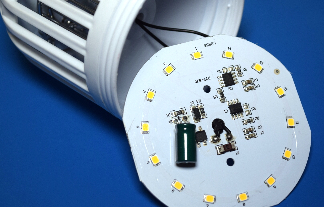
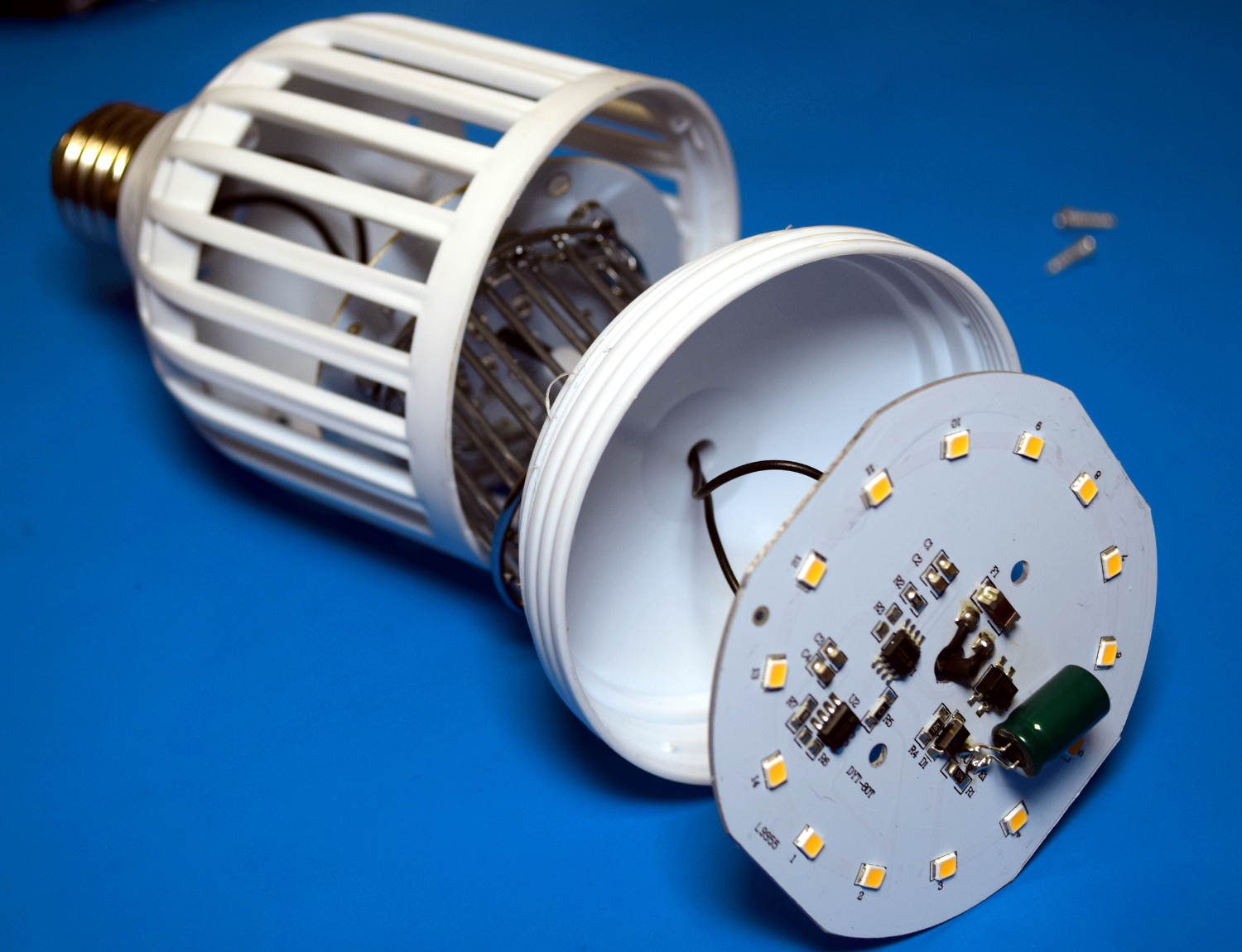
Under the frosted plastic dome on the front of the zapper bulb is…well, what you’d expect to find inside of a cheap LED bulb. A few years ago this kind of thing might be novel, but we’ve seen it all before.
With just fourteen run-of-the-mill diodes, the light produced from this bulb isn’t particularly impressive. According to the manual it’s putting out 600 lumens, which would put it just slightly north of what you’d expect from an old school 40 W incandescent bulb. Being a relatively low-power array there’s no external heatsink on the bulb, the aluminum backing of the PCB seems enough to keep things cool.
The limited light output is made worse by the fact that all the diodes point forward, making this more of a bad spotlight than anything. Arguably that might be desirable outside, especially if this was placed in a high light socket and you wanted to throw a beam down on a porch or deck. But in that case it would have been nice if they actually indicated that by giving the bulb a more distinct spotlight shape.
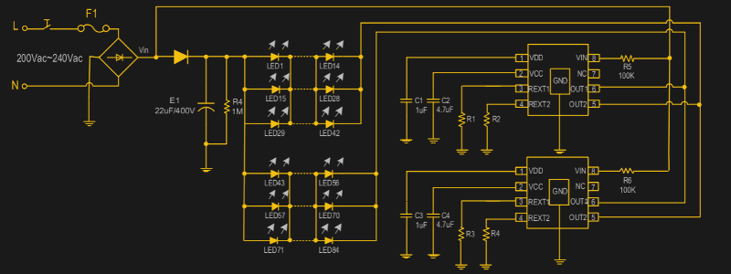
Beyond the LEDs, the only components of any note are the dual SM2212EA driver ICs. I couldn’t find an English datasheet for these, but a rough online translation of the PDF provided the highlights: they run on 90 to 240 VAC, offer a two-stage brightness control, and have built in thermal shutdown. But the fact that there are two of them seemed odd, and on closer inspection, the way they were connected didn’t seem to make any sense.
With the traces highlighted, it’s clear both ICs are tied together.
The answer comes from the datasheet, which explains on one of the final pages that if the power requirements are so high that a single SM2212EA goes into thermal overload, you can simply duplicate the single chip application and tie their outputs together to run them in parallel. Each chip has two output pins because one is the full brightness pin that comes on first, and the second is the reduced current pin that dims the LEDs after the power switch has been flicked on and off.
That makes sense, except for one problem: the LEDs on this product don’t actually dim. When you flick the switch on the first time the light and zapper functions are both on, and when you flip it again, the LEDs go off completely while the zapper stays on. So what’s going on?
While the datasheet isn’t very clear, it seems that the resistor connected to pin 4 of the SM2212EA is used to set the amount of current the secondary dimming pin will pass. But a close look at the PCB shows that this resistor is missing for both chips (pads R3 and R6 on the silkscreen, R2 and R4 on diagram), so the dimming function is essentially disabled. If you were so inclined you should be able to drop a pair of 200 ohm resistors across those pads to turn it back on, but you’d lose the ability to use the zapper without the light on.
Ride the Lightning
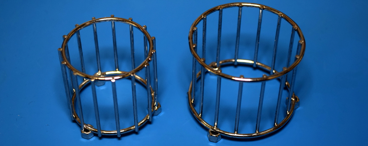
Below the LED PCB and on the other side of a little plastic bulkhead, we find the electrified elements that do the actual zapping of bugs. They appear preposterously overbuilt for this application, which makes me think more thought was given to the aesthetics of the shiny chrome grid than its bug-busting properties. It seems like a tighter grid of smaller diameter wires would have been more effective, but wouldn’t have looked nearly as nice sitting on the shelf or during the late-night TV infomercial.
On the plus side they’re attached to the high-voltage PCB with nothing more exotic than some M3 screws, so they can be easily removed for potential modification or reuse. At the center of the grid are four UV LEDs which serve as the “bait” to bring the bugs in. Now as we’ve learned from the COVID pandemic, not all UV LEDs are created equal, and these are probably only good for attracting bugs. (Oh wait.)
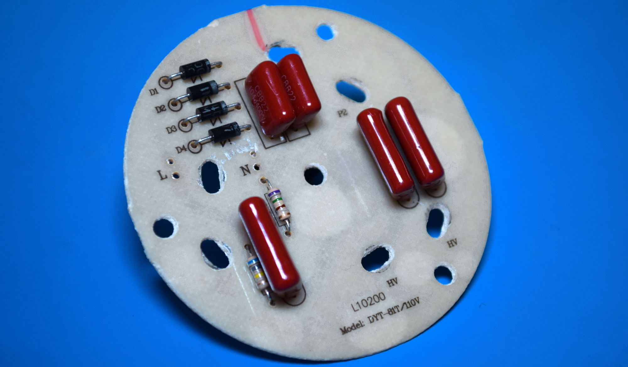
Taking a look at the back of the HV PCB, we can see just how simple of an arrangement we’re dealing with. There’s no transformer involved, just a basic voltage multiplier circuit using four pairs of diodes and capacitors. That gives a maximum potential of a little under 500 VDC when running at 120 VAC here in the US, which as far as I can tell, is exceptionally poor for a bug zapper. A quick perusal of Amazon shows even the relatively cheap models are advertising grid voltages of 3 to 4 kV.
For the record, I didn’t lose count. The fifth capacitor off to the left side with the pair of diodes is being used to provide the power for the UV LEDs on the other side of the board, and doesn’t appear to be connected to the HV side of things.
Master of None
So on the top we have a pretty ho-hum LED bulb, and on the bottom, a photogenic but ultimately anemic bug zapper. Through a pair of legitimately hacked dimmer ICs, the user has the ability to turn off the LEDs, but the high voltage zapper is live whenever the power is supplied. Though to be fair, it’s hard to imagine a scenario in which somebody would buy one of these things but not want to use the zapper function.
I can’t say that it’s poorly built, in fact, I was somewhat impressed by how competently everything seemed to be put together. But functionally, I’d be hesitant to pay the full $20 USD MRSP. If you’ve got a bug problem, you’d be better served with a real zapper that has a bigger UV light source (often a small fluorescent bulb) and a more powerful HV source. That said, if you see one of these drifting around the clearance rack for a buck or two, it’s probably worth salvaging its internal components to power your high voltage adventures.
Up here in the Northern Hemisphere, mosquitoes and other flying pests are the last thing on anyone’s mind right now. The only bug that’s hindering gatherings at the moment goes by the name of COVID-19, but even if we weren’t social distancing, insects simply aren’t a concern at this time of year. So it’s little surprise that these months are often the best time to find a great deal on gadgets designed to deter or outright obliterate airborne insects.
Whatever PIC stands for…it’s not that.
Case in point, I was able to pick up this “Bug Zapper LED Bulb” at the big-box hardware store for just a few bucks. This one is sold by PIC Corporation, though some press release surfing shows the company merely took over distribution of the device in 2017. Before then it was known as the Zapplight, and was the sort of thing you might see advertised on TV if you were still awake at 3 AM. It appears there are several exceptionally similar products on the market as well, which are likely to be the same internally.
In all fairness, it’s a pretty clever idea. Traditional zappers are fairly large, and need to be hoisted up somewhere next to an electrical outlet. But if you could shrink one down to the size of a light bulb, you could easily dot them around the porch using the existing sockets and wiring. Extra points if you can also figure out a way to make it work as a real bulb when the bugs aren’t out. Obviously the resulting chimera won’t excel at either task, but there’s certainly something to be said for the convenience of it.
Let’s take a look inside one of these electrifying illuminators and see how they’ve managed to squeeze two very different devices into one socket-friendly package.
Let there Be Light
Under the frosted plastic dome on the front of the zapper bulb is…well, what you’d expect to find inside of a cheap LED bulb. A few years ago this kind of thing might be novel, but we’ve seen it all before.
With just fourteen run-of-the-mill diodes, the light produced from this bulb isn’t particularly impressive. According to the manual it’s putting out 600 lumens, which would put it just slightly north of what you’d expect from an old school 40 W incandescent bulb. Being a relatively low-power array there’s no external heatsink on the bulb, the aluminum backing of the PCB seems enough to keep things cool.
The limited light output is made worse by the fact that all the diodes point forward, making this more of a bad spotlight than anything. Arguably that might be desirable outside, especially if this was placed in a high light socket and you wanted to throw a beam down on a porch or deck. But in that case it would have been nice if they actually indicated that by giving the bulb a more distinct spotlight shape.
Beyond the LEDs, the only components of any note are the dual SM2212EA driver ICs. I couldn’t find an English datasheet for these, but a rough online translation of the PDF provided the highlights: they run on 90 to 240 VAC, offer a two-stage brightness control, and have built in thermal shutdown. But the fact that there are two of them seemed odd, and on closer inspection, the way they were connected didn’t seem to make any sense.
With the traces highlighted, it’s clear both ICs are tied together.
The answer comes from the datasheet, which explains on one of the final pages that if the power requirements are so high that a single SM2212EA goes into thermal overload, you can simply duplicate the single chip application and tie their outputs together to run them in parallel. Each chip has two output pins because one is the full brightness pin that comes on first, and the second is the reduced current pin that dims the LEDs after the power switch has been flicked on and off.
That makes sense, except for one problem: the LEDs on this product don’t actually dim. When you flick the switch on the first time the light and zapper functions are both on, and when you flip it again, the LEDs go off completely while the zapper stays on. So what’s going on?
While the datasheet isn’t very clear, it seems that the resistor connected to pin 4 of the SM2212EA is used to set the amount of current the secondary dimming pin will pass. But a close look at the PCB shows that this resistor is missing for both chips (pads R3 and R6 on the silkscreen, R2 and R4 on diagram), so the dimming function is essentially disabled. If you were so inclined you should be able to drop a pair of 200 ohm resistors across those pads to turn it back on, but you’d lose the ability to use the zapper without the light on.
Ride the Lightning
Below the LED PCB and on the other side of a little plastic bulkhead, we find the electrified elements that do the actual zapping of bugs. They appear preposterously overbuilt for this application, which makes me think more thought was given to the aesthetics of the shiny chrome grid than its bug-busting properties. It seems like a tighter grid of smaller diameter wires would have been more effective, but wouldn’t have looked nearly as nice sitting on the shelf or during the late-night TV infomercial.
On the plus side they’re attached to the high-voltage PCB with nothing more exotic than some M3 screws, so they can be easily removed for potential modification or reuse. At the center of the grid are four UV LEDs which serve as the “bait” to bring the bugs in. Now as we’ve learned from the COVID pandemic, not all UV LEDs are created equal, and these are probably only good for attracting bugs. (Oh wait.)
Taking a look at the back of the HV PCB, we can see just how simple of an arrangement we’re dealing with. There’s no transformer involved, just a basic voltage multiplier circuit using four pairs of diodes and capacitors. That gives a maximum potential of a little under 500 VDC when running at 120 VAC here in the US, which as far as I can tell, is exceptionally poor for a bug zapper. A quick perusal of Amazon shows even the relatively cheap models are advertising grid voltages of 3 to 4 kV.
For the record, I didn’t lose count. The fifth capacitor off to the left side with the pair of diodes is being used to provide the power for the UV LEDs on the other side of the board, and doesn’t appear to be connected to the HV side of things.
Master of None
So on the top we have a pretty ho-hum LED bulb, and on the bottom, a photogenic but ultimately anemic bug zapper. Through a pair of legitimately hacked dimmer ICs, the user has the ability to turn off the LEDs, but the high voltage zapper is live whenever the power is supplied. Though to be fair, it’s hard to imagine a scenario in which somebody would buy one of these things but not want to use the zapper function.
I can’t say that it’s poorly built, in fact, I was somewhat impressed by how competently everything seemed to be put together. But functionally, I’d be hesitant to pay the full $20 USD MRSP. If you’ve got a bug problem, you’d be better served with a real zapper that has a bigger UV light source (often a small fluorescent bulb) and a more powerful HV source. That said, if you see one of these drifting around the clearance rack for a buck or two, it’s probably worth salvaging its internal components to power your high voltage adventures.
The Z80 was a big deal in the 1970s and 1980s, and while its no longer a dominant architecture today, its legacy lives on. [James Andrew Fitzjohn] is a fan of the Z, and decided to interface the real silicon with the Raspberry Pi, by and large for the fun of it!
The Z80’s address and data lines, as well as the clock, are hooked up to the Raspberry Pi through several MCP23017 GPIO expanders. The Pi’s GPIO lines aren’t known for their speed, of course, and using expanders through I2C isn’t exactly quick either. However, speed isn’t necessary, as the clock only goes as fast as the Raspberry Pi desires, since it’s controlling the clock along with everything else. There’s also an LCD for viewing the Z80s status, along with some era-appropriate blinkenlights.
This setup allows the Pi to run code directly on the Z80 itself, while managing the CPU’s RAM in its own memory, all through a Python script. It’s a fun hack that lets you run retro code on retro silicon without using an emulator. Techniques like these are useful for finding undocumented or edge case performance of a processor. If this hack isn’t enough Zilog for your liking, consider throwing one in your pocket as well!
The city of Oldsmar, Florida was the source of disturbing news this week, among reports that someone gained unauthorized access to a water treatment facility. In an era where more systems than ever are connected to the Internet, the story is a sobering one for the vast majority of people reliant on grid utilties.
The hacker was first noticed to have gained remote access to a computer system at the plant at 8 a.m. on February 5. An operator at a workstation controlling chemical dosing at the plant observed a remote connection, though did not initially raise the alarm as such access is common practice at the facility for troubleshooting purposes. However, at 1:30 pm, the hacker connected again, this time commanding the dosing system to raise levels of sodium hydroxide in the water from 100 to 11,000 ppm – dangerous levels that would make the city’s water unsafe to drink. The increased level command was immediately overridden by the operator, who then raised the alarm.
The city notes that other safeguards such as pH monitors at the plant would have triggered in the event the original intrusion went undetected. However, the event raises renewed questions about the level of security around critical utility systems connected to the internet. In the last decade, cyberattacks on physical infrastructure have become a reality, not a vague future threat.
Nothing’s known yet about the perpetrator, or how secure the system was (or wasn’t?) before the event. It’s been long known that a lot of infrastructure is simply connected to the internet, as Dan Tentler has been showing us since at least 2012. (Video, ranting.) Indeed, it’s amazing that we’ve seen so few malicious attacks.
Here at Hackaday we’re always exited to see hacks that recycle our favorite childhood consoles into something new and interesting. In that context, it’s not so uncommon to see mods which combine new and unusual control methods with old devices in ways that their manufacturers never intended. What [Mike Choi] has built with the Labo Fit Adventure Kit is the rare hack that combines radically new control schemes with a modern console: without actually modifying any hardware.
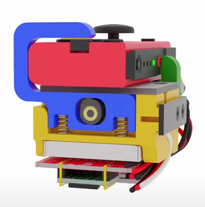
Face button pusher in blue
In short, the Labo Fit Adventure Kit lets the player play Mario Kart on the Nintendo Switch by riding a stationary exercise bike, steering with a wheel, and squeezing that wheel to use items. The Fit Kit combines the theme of Labo, Nintendo’s excellent cardboard building kit for the Nintendo Switch with the existing Ring-Con accessory for the unrelated Nintendo game Ring Fit Adventure plus a collection of custom hardware to tie it all together. That hardware senses cadence on the stationary bike, watches for the user to squeeze the handheld wheel controller, and translates those inputs to button presses on the controller to play the game.
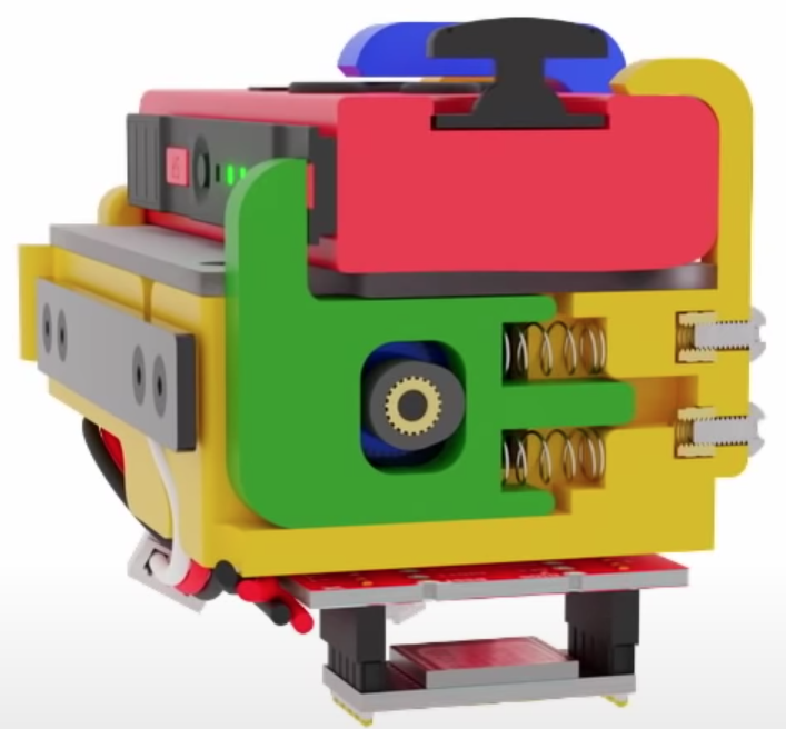
Shoulder button pusher in green
The most fascinating element of this project is the TAPBO module which adapts the Joy-Con controller to remote input. The module includes electronics, actuators, and a clever mechanical design to allow it to be mounted to the Ring-Con in place of an unmodified Joy-Con. Electrically the components will be familiar to regular Hackaday readers; there is a breakout board for a Teensy which also holds an XBee module to receive inputs remotely and drive a pair of servos. The entire module is described in detail starting at 4:42 in the video.
Mechanically the TAPBO relies on a pair of cam-actuated arms which translate rotational servo motion into linear action to press shoulder or face buttons. The module directly measures flex of the Ring-Con with an added flexible resistor and receives cadence information from another module embedded in the stationary bike via Zigbee. When these inputs exceed set thresholds they drive the servos to press the appropriate controller buttons to accelerate or use an item.
We’ve focused pretty heavily on the technical aspects of this project, but this significantly undersells the level of polish and easy to understand documentation [Mike] has produced. It includes a TAPBO Amiibo in customized packaging, and more. Check out the full video to get the complete scope of this project.
Here at Hackaday we’re always exited to see hacks that recycle our favorite childhood consoles into something new and interesting. In that context, it’s not so uncommon to see mods which combine new and unusual control methods with old devices in ways that their manufacturers never intended. What [Mike Choi] has built with the Labo Fit Adventure Kit is the rare hack that combines radically new control schemes with a modern console: without actually modifying any hardware.
Face button pusher in blue
In short, the Labo Fit Adventure Kit lets the player play Mario Kart on the Nintendo Switch by riding a stationary exercise bike, steering with a wheel, and squeezing that wheel to use items. The Fit Kit combines the theme of Labo, Nintendo’s excellent cardboard building kit for the Nintendo Switch with the existing Ring-Con accessory for the unrelated Nintendo game Ring Fit Adventure plus a collection of custom hardware to tie it all together. That hardware senses cadence on the stationary bike, watches for the user to squeeze the handheld wheel controller, and translates those inputs to button presses on the controller to play the game.
Shoulder button pusher in green
The most fascinating element of this project is the TAPBO module which adapts the Joy-Con controller to remote input. The module includes electronics, actuators, and a clever mechanical design to allow it to be mounted to the Ring-Con in place of an unmodified Joy-Con. Electrically the components will be familiar to regular Hackaday readers; there is a breakout board for a Teensy which also holds an XBee module to receive inputs remotely and drive a pair of servos. The entire module is described in detail starting at 4:42 in the video.
Mechanically the TAPBO relies on a pair of cam-actuated arms which translate rotational servo motion into linear action to press shoulder or face buttons. The module directly measures flex of the Ring-Con with an added flexible resistor and receives cadence information from another module embedded in the stationary bike via Zigbee. When these inputs exceed set thresholds they drive the servos to press the appropriate controller buttons to accelerate or use an item.
We’ve focused pretty heavily on the technical aspects of this project, but this significantly undersells the level of polish and easy to understand documentation [Mike] has produced. It includes a TAPBO Amiibo in customized packaging, and more. Check out the full video to get the complete scope of this project.
Here at Hackaday we’re always exited to see hacks that recycle our favorite childhood consoles into something new and interesting. In that context, it’s not so uncommon to see mods which combine new and unusual control methods with old devices in ways that their manufacturers never intended. What [Mike Choi] has built with the Labo Fit Adventure Kit is the rare hack that combines radically new control schemes with a modern console: without actually modifying any hardware.
Face button pusher in blue
In short, the Labo Fit Adventure Kit lets the player play Mario Kart on the Nintendo Switch by riding a stationary exercise bike, steering with a wheel, and squeezing that wheel to use items. The Fit Kit combines the theme of Labo, Nintendo’s excellent cardboard building kit for the Nintendo Switch with the existing Ring-Con accessory for the unrelated Nintendo game Ring Fit Adventure plus a collection of custom hardware to tie it all together. That hardware senses cadence on the stationary bike, watches for the user to squeeze the handheld wheel controller, and translates those inputs to button presses on the controller to play the game.
Shoulder button pusher in green
The most fascinating element of this project is the TAPBO module which adapts the Joy-Con controller to remote input. The module includes electronics, actuators, and a clever mechanical design to allow it to be mounted to the Ring-Con in place of an unmodified Joy-Con. Electrically the components will be familiar to regular Hackaday readers; there is a breakout board for a Teensy which also holds an XBee module to receive inputs remotely and drive a pair of servos. The entire module is described in detail starting at 4:42 in the video.
Mechanically the TAPBO relies on a pair of cam-actuated arms which translate rotational servo motion into linear action to press shoulder or face buttons. The module directly measures flex of the Ring-Con with an added flexible resistor and receives cadence information from another module embedded in the stationary bike via Zigbee. When these inputs exceed set thresholds they drive the servos to press the appropriate controller buttons to accelerate or use an item.
We’ve focused pretty heavily on the technical aspects of this project, but this significantly undersells the level of polish and easy to understand documentation [Mike] has produced. It includes a TAPBO Amiibo in customized packaging, and more. Check out the full video to get the complete scope of this project.
Cluster computing is a popular choice for heavy duty computing applications. At the base level, there are hobby clusters often built with Raspberry Pis, while the industrial level involves data centers crammed with servers running at full tilt. [greg] wanted something cheap, but with x86 support – so set about building a rig his own way.
The ingenious part of [greg]’s build comes in the source computers. He identified that replacement laptop motherboards were a great source of computing power on the cheap, with a board packing an i7 CPU with 16GB of RAM available from eBay for around £100, and with i5 models being even cheaper. With four laptop motherboards on hand, he set about stacking them in a case, powering them, and hooking them up with the bare minimum required to get them working. With everything wrapped up in an old server case with some 3D printed parts to hold it all together, he was able to get a 4-node Kubernetes cluster up and running for an absolute bargain price.
We haven’t seen spare laptop motherboards used in such a way before, but we could definitely see this becoming more of a thing going forward. The possibilities of a crate full of deprecated motherboards are enticing for those building clusters on the cheap. Of course, more nodes is more better, so check out this 120 Pi cluster to satiate your thirst for raw FLOPs.
When [Kai Robinson] found himself faced with the difficult task of saving as many Mac SE’s as he possibly could, the logical but daunting answer was to recreate the Mac SE logic board for machines that would otherwise be scrapped. These machines are over 30 years old and the PRAM battery often leaks, destroying parts and traces. Given that the logic board is a simple through-hole two-layer board, how hard could it be?
The first step was to get some reference photos so [Kai] set to desoldering everything on the board. The list of components and the age of solder made this an arduous task. Then a composite image was produced by merging images together using a scanner and some Inkscape magic. Rather than simply putting the pins in the right place and re-routing all the netlists, [Kai] elected instead to do a copy, trace for trace of the original SE board. [Kai] and several others on the forum have been testing the boards and tracking down the last few bugs and kinks in the design. An unconnected pin here and an improperly impedance matched resistor there. Hopefully, soon they’ll have Gerbers and design files ready for anyone should they need a new logic board PCB.
It’s no secret that we love the Macintosh SE here at Hackaday. We’ve seen new custom cases for it and now new PCBs for it. It does cause the mind to ponder though and wonder, what’s next?
Whether you’re live streaming builds or just want to take your project photography to the next level, you can’t beat an overhead camera setup. Unfortunately, they tend to be cumbersome and more often than not quite pricey. Looking for an affordable solution that could easily be moved out of the way when not in use, [Jay Doscher] had the clever idea of adapting a common VESA monitor arm to give his camera a bird’s eye view of the action.
If you think about it, one of these monitor arms is a nearly perfect base for a camera rig. They’re easily mounted to a desk or work bench, can be quickly repositioned by design, and perhaps best of all, you don’t have to spend a lot of money to get a decent one. A camera is also a far lighter and less awkward payload than the arm was designed to hold, so you don’t have to worry about it potentially dropping your expensive gear. Or cheap webcam, as the case may be.
All [Jay] had to do was come up with a way to securely mount his Sony A7R3 on the end of one. While there’s certainly a few ways you could solve this particular problem, he went the extruded plastic route and 3D printed a beefy adapter plate with the standard VESA bolt pattern. His Smallrig camera cage attaches to the plate, and thanks to a pair of press-fit bubble levels from McMaster Carr, he’s able to get everything lined up properly over the bench.
Of course, there’s an excellent chance you don’t have the same camera as [Jay]. But that doesn’t mean you can’t modify the design of his adapter to fit your own gear. To that end, he’s not only shared the final STLs, but he’s provided a link to the TinkerCAD project that you can actually edit right in the browser.
If you’ve got a light enough camera, you could put something similar together with PVC pipes or even an articulated arm intended for a desk lamp. But if you’ve got a DSLR or other full-sized camera, we think it’s more than worth the $30 USD one of these will cost you on Amazon to make sure your gear doesn’t end up smashing into the deck during a live stream.
Back in the 1970s, there were a huge variety of esoteric LED displays on the market. One of those was the DIP-packaged TIL311 from Texas Instruments, capable of displaying hexadecimal, from 0-9 and A-F. While these aren’t readily available anymore, the deep red plastic packages had some beauty to them, so [Alex] set about making a modern recreation.
The build consists of a small PCB fitted with 20 LEDs, and a STM8S microcontroller to run the show. This can be used to emulate the original decoder logic on the TIL311, or programmed with other firmware in order to test the display or enable other display functions. Where the project really shines however is in the visual presentation. [Alex] has been experimenting with potting the hardware in translucent red resin to properly emulate the look of the original parts, which goes a long way to getting that cool 70s aesthetic. Attention to detail is top notch, with [Alex] going so far as to carefully select pins that most closely match the square-cut design on the original TIL311 part.
For the past seven months, NASA’s newest Mars rover has been closing in on its final destination. As Perseverance eats up the distance and heads for the point in space that Mars will occupy on February 18, 2021, the rover has been more or less idle. Tucked safely into its aeroshell, we’ve heard little from the lonely space traveler lately, except for a single audio clip of the whirring of its cooling pumps.
Its placid journey across interplanetary space stands in marked contrast to what lies just ahead of it. Like its cousin and predecessor Curiosity, Perseverance has to successfully negotiate a gauntlet of orbital and aerodynamic challenges, and do so without any human intervention. NASA mission planners call it the Seven Minutes of Terror, since the whole process will take just over 400 seconds from the time it encounters the first wisps of the Martian atmosphere to when the rover is safely on the ground within Jezero Crater.
For that to happen, and for the two-billion-dollar mission to even have a chance at fulfilling its primary objective of searching for signs of ancient Martian life, every system on the spacecraft has to operate perfectly. It’s a complicated, high-energy ballet with high stakes, so it’s worth taking a look at the Seven Minutes of Terror, and what exactly will be happening, in detail.
Slow Down There, Buddy
To fully understand the enormity of the undertaking of landing a rover on Mars, the first thing to grasp is the scale of the problem. At the time of launch back in July, Mars and Earth were in optimal orbital positions relative to each other to keep the 480 million km crossing time to a minimum. But Perseverance was built for a very specialized mission, and therefore is headed for a very specific spot on the Red Planet.
Jezero Crater, Perseverance’s target, is an ancient lake bed about 40 km across, making it a very small target to hit on a plant the size of Mars. But that’s not the half of it. The northwest quadrant of Jezero shows evidence of a delta system, where the flow of water in the ancient river that once fed into the crater slowed and dropped its load of silt and sediment. On Earth, river deltas are highly productive biologically; planetary scientists think that if there was ever life there, the delta is the place to look. Landing near that delta system while avoiding boulder-strewn areas of the crater left mission planners aiming Perseverance at an ellipse only 7 km by 8 km.
The other problem of scale is the sheer size of Perseverance. Like the Curiosity rover that it’s based on, Perseverance is huge — about the size of a compact car. It measures three meters in length and has a mass of over 1,000 kilograms. Getting a package that size slowed down enough to land safely on the surface is a major challenge. But luckily, it’s a challenge that flight controllers have faced before, and one they conquered. Perseverance will follow nearly the same entry, descent, and landing (EDL) stages of the mission as Curiosity did back in 2012; NASA has produced a wonderful animation of the EDL phase of the mission that makes a great visual aid to the following play-by-play.
EDL starts when Perseverance sheds its supporting cruise stage, with the solar panels and maneuvering engines needed for the trip from Earth, along with two 70-kg balance masses, and first encounters the Martian atmosphere. The spacecraft will be traveling at about 20,000 km/h at that point, and will need to safely shed an enormous amount of kinetic energy in the next few minutes. The aeroshell covering the leading edge of the spacecraft will bear the brunt of this energy, turning the ablative heat shield of honeycomb aluminum and phenolic resin into a streak of plasma across the thin Martian upper atmosphere.
As on Earth, the Martian atmosphere is a turbulent place, and Perseverance will need to adjust its trajectory with continual thruster bursts to make sure it stays on track. During this guidance phase, which includes a maneuver called SUFR, or “straighten up and fly right”, the spacecraft will slow down to 1,500 km/h. It is at this point where the most dramatic part of the early EDL stage occurs: parachute deployment. The backshell of the spacecraft has a 21-m supersonic nylon and kevlar parachute tucked into it, which is deployed and inflates within 500 milliseconds. This produces over 311 kN of drag force on the spacecraft, slowing it further. If this all goes well, Perseverance will have survived about four and a half minutes of its seven-minute thrill ride.
The Skycrane
The final 150 seconds of EDL wil be somewhat calmer than the preceding breakneck race to 11 km above the Martian surface, but there are still more dramatic events in store for the mission. After the heat shield drops off the bottom of the package at an altitude of about 10 km, downward-looking cameras will begin the process of comparing what Perseverance sees below it to a high-resolution photo of its target, stored in the rover’s memory. Called Terrain Relative Navigation, this phase of EDL was not done for Curiosity, which was one reason the landing zone for the previous rover was so much larger (20 km by 25 km). TRN should allow Perseverance a landing accuracy of about 40 meters while avoiding any large obstacles.
The TRN process only takes about 20 seconds, during which time Perseverance will still be attached to its backshell. The parachute will have bled off as much energy as it can in the thin Martian atmosphere by this point, and at an altitude of 2,000 meters and a speed of about 300 km/h, the rover, attached to its powered descent stage, will release from the backshell. After free-falling for a few seconds, the eight hydrazine-fueled thrusters ringing the descent stage will fire for about the next 30 seconds, both slowing the spacecraft further as well as maneuvering it to the landing spot selected during TRN.
Now within 20 meters of the surface, and slowed to 25 km/h of vertical speed and almost zero horizontal speed, the single most dramatic and technically complex maneuver of the whole EDL process begins: skycrane deployment. In order to prevent contamination of the landing site by descent-stage propellants and to prevent kicking up dust which could obscure cameras and damage systems on the rover, the descent stage will instead lower the 1,000-kg rover to the surface on three nylon cords. The rover’s wheels, which have been folded under its hull for the last seven months, will finally rotate into the deployed position as the descent stage gently lowers the machine to the surface. If all goes well, the rover will make a six-point touchdown at a graceful vertical speed of 2 km/h.
I’ll Fly Away
Once the rover reports touchdown, explosive “guillotine” fittings on the upper hull fire to cut the skycrane cords and the small umbilical connecting it to the descent stage. Once the ascent stage confirms that it has cleanly separated from the rover, the descent engines will throttle up and gimbal to steer the descent stage away from the landing site at a 45-degree elevation, to maximize the distance between it and the rover. The descent stage will fly until its hydrazine tanks run dry, at which point the nearly inert vehicle will crash into the Martian surface well outside of Jezero crater.
Back at the landing site, Perseverance will be undertaking some early system checks and reporting back to controllers. Once we find out about it, 11 minutes later, Perseverance will be ready to start its ground operations and its primary mission of collecting samples for a future sample-return mission. As a side benefit, the 20-odd video cameras and microphones on the rover and in the descent stage, which will be active during the EDL, will have captured the landing in great detail. It’ll be weeks before that data is uploaded back to Earth, but when it’s finally ready for viewing, it ought to be pretty spectacular.
By the time you read this, Perseverance will be only about ten days away from its date with destiny. Coordinating the fast-paced, high-stakes events of the EDL phase of the mission seems almost like an impossible feat of engineering, especially given that it must be completed autonomously. If it weren’t for the precedent of Curiosity’s successful landing, there would be ample room for skepticism that this could be pulled off at all. There will certainly be a lot of tension in Mission Control and around the world as we watch events unfold on the live stream, but with a little luck, Perseverance will be able to repeat its cousin’s success and perhaps even exceed it.
As for coverage, NASA will be live-streaming the landing on their YouTube channel, so make sure to tune in if you can. The coverage will start on February 18, 2021 at 11:15 AM Pacific Standard Time (UTC-8). We’ve created a handy time zone converter and countdown so you don’t miss the show.
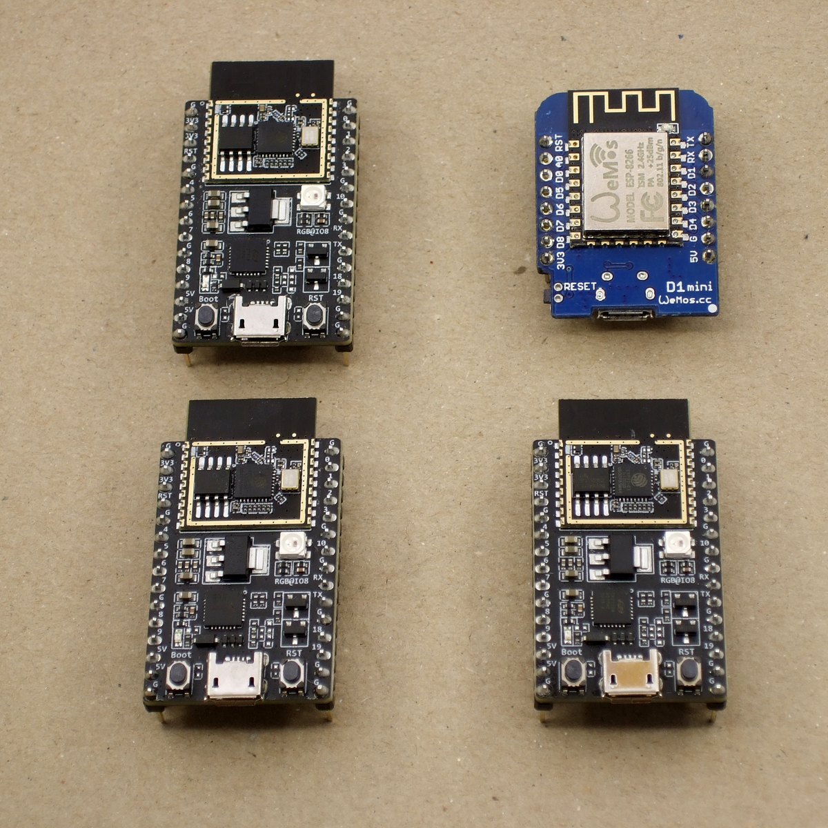
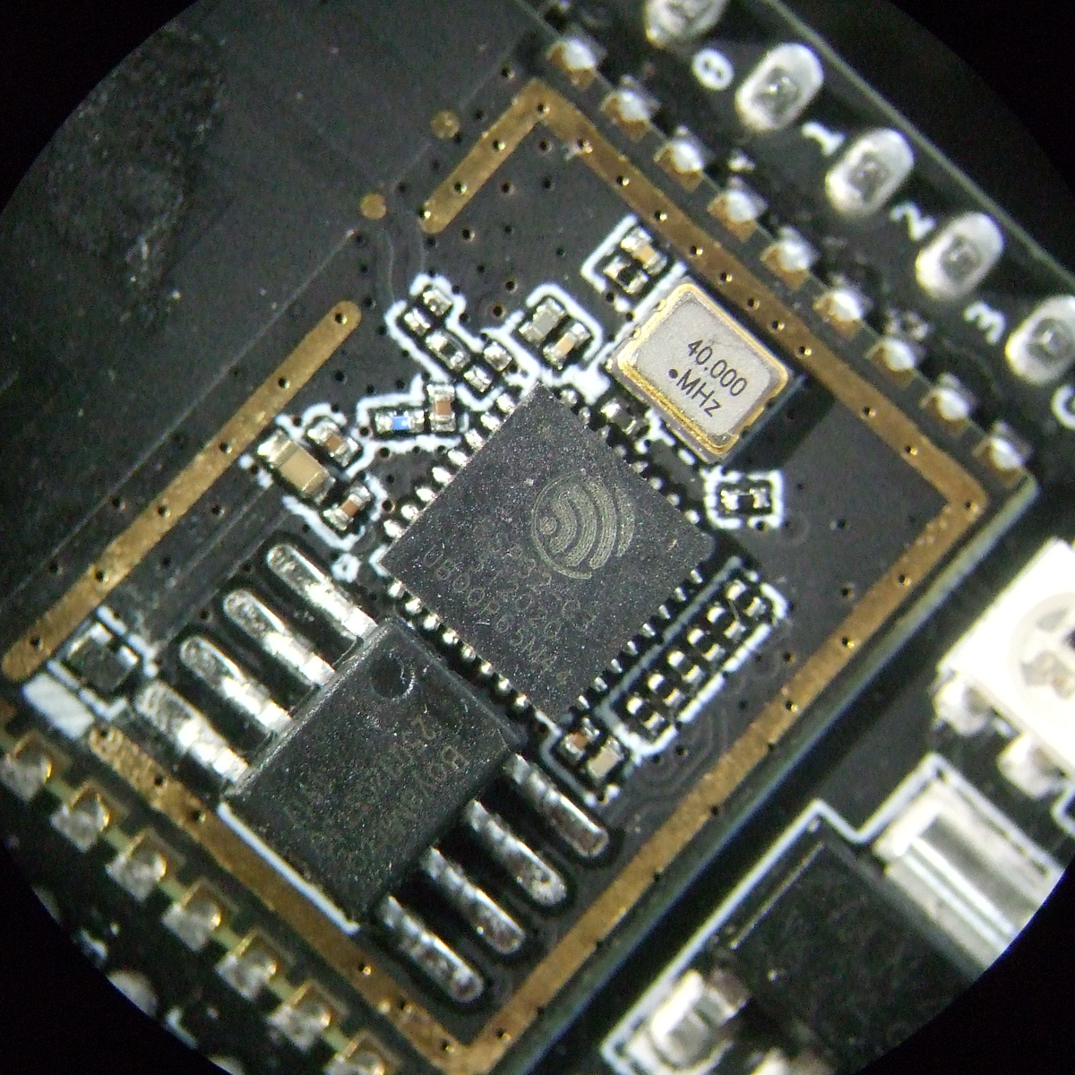
We just got our hands on some engineering pre-samples of the ESP32-C3 chip and modules, and there’s a lot to like about this chip. The question is what should you compare this to; is it more an ESP32 or an ESP8266? The new “C3” variant has a single 160 MHz RISC-V core that out-performs the ESP8266, and at the same time includes most of the peripheral set of an ESP32. While RAM often ends up scarce on an ESP8266 with around 40 kB or so, the ESP32-C3 sports 400 kB of RAM, and manages to keep it all running while burning less power. Like the ESP32, it has Bluetooth LE 5.0 in addition to WiFi.
Espressif’s website says multiple times that it’s going to be “cost-effective”, which is secret code for cheap. Rumors are that there will be eight-pin ESP-O1 modules hitting the streets priced as low as $1. We usually require more pins, but if medium-sized ESP32-C3 modules are priced near the ESP8266-12-style modules, we can’t see any reason to buy the latter; for us it will literally be an ESP8266 killer.
On the other hand, it lacks the dual cores of the ESP32, and simply doesn’t have as many GPIO pins. If you’re a die-hard ESP32 abuser, you’ll doubtless find some features missing, like the ultra-low-power coprocessor or the DACs. But it does share a lot of the ESP32 standouts: the LEDC (PWM) peripheral and the unique parallel I2S come to mind. Moreover, it shares the ESP-IDF framework with the ESP32, so despite running on an entirely different CPU architecture, a lot of code will run without change on both chips just by tweaking the build environment with a one-liner.
One of these things is not like the other
If you were confused by the chip’s name, like we were, a week or so playing with the new chip will make it all clear. The ESP32-C3 is a lot more like a reduced version of the ESP32 than it is like an improvement over the ESP8266, even though it’s probably destined to play the latter role in our projects. If you count in the new ESP32-S3 that brings in USB, the ESP32 family is bigger than just one chip. Although it does seem odd to lump the RISC-V and Tensilica CPUs together, at the end of the day it’s the peripherals more than the CPUs that differentiate microcontrollers, and on that front the C3 is firmly in the ESP32 family.
Our takeaway: the ESP32-C3 is going to replace the ESP8266 in our projects, but it won’t replace the ESP32 which simply has more of everything when we need it. The shared codebase and peripheral architecture makes it easier to switch between the two when we don’t need the full-blown ESP32. In that spirit, we welcome the newcomer to the family.
But naturally, we’ve got a lot more to say about it. Specifically, we were interested in exactly what the RISC-V core brought to the table, and ran the module through power and speed comparisons with the ESP32 and ESP8266 — and it beats them both by a small margin in our benchmarks. We’ve also become a lot closer friends with the ESP-IDF SDK that all of the ESP32 family chips use, and love how far it has come in the last year or so. It’s not as newbie-friendly as ESP-Arduino, for sure, but it’s a ton more powerful, and we’re totally happy to leave the ESP8266 SDK behind us.
RISC-V: Power and Speed
The ESP32-C3 shares the coding framework with the ESP32, some of the peripherals, and has about the same amount of memory. What’s different? The RISC-V CPU of the C3 vs. the Tensilica cores in the ESP32 and the ESP8266. So we thought we’d put them through their paces and see how they stack up in terms of processing speed and overall power use.
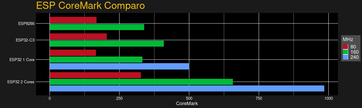
In terms of standard benchmarks for microcontrollers and other embedded devices, CoreMark is probably the go-to. And we found that it had been already ported to the ESP8266 and ESP32 by [Ochrin]. (Thanks!) CoreMark includes three tests: finding and sorting with linked lists to tax the memory units, running a state machine to test switch/case branching speed, and a matrix multiplication task to tax the CPU and compiler.
In practice, and mimicking our general experience with the ESP8266 and ESP32 frameworks, the code compiled without any hassle for the ESP32 and ESP32-C3. In contrast, getting it running on the ESP8266 was a hair-pulling few hours spent degrading versions of the RTOS framework, installing modules in Python 2 inside virtualenvs, and getting the set of PATHs and other environment variables just right. But we weren’t going to leave you without a proper comparo, so we burned the midnight oil.
The takeaway is that a single RISC-V core on the ESP32-C3 is marginally faster per MHz than a single core on either of the Tensilica-based devices. Of course, if you’re crunching numbers hard and using both cores of the ESP32, it’s in another league, and you know who you are. But if you’re running Arduino on the ESP32 and you’re not explicitly running the RTOS tasks yourself, or running MicroPython and not using threads, you’re probably running a single core on the ESP32 anyway. Modulo some small difference in having a free core to exclusively handle WiFi, you might not be much worse off with the C3.
While running this test, we also hooked up our super-sophisticated power measuring unit to the devices under test, a USB cable with three 3 Ω resistors and an oscilloscope. Of course, if you simply wanted the chip’s power specs, you could hit up the datasheet.
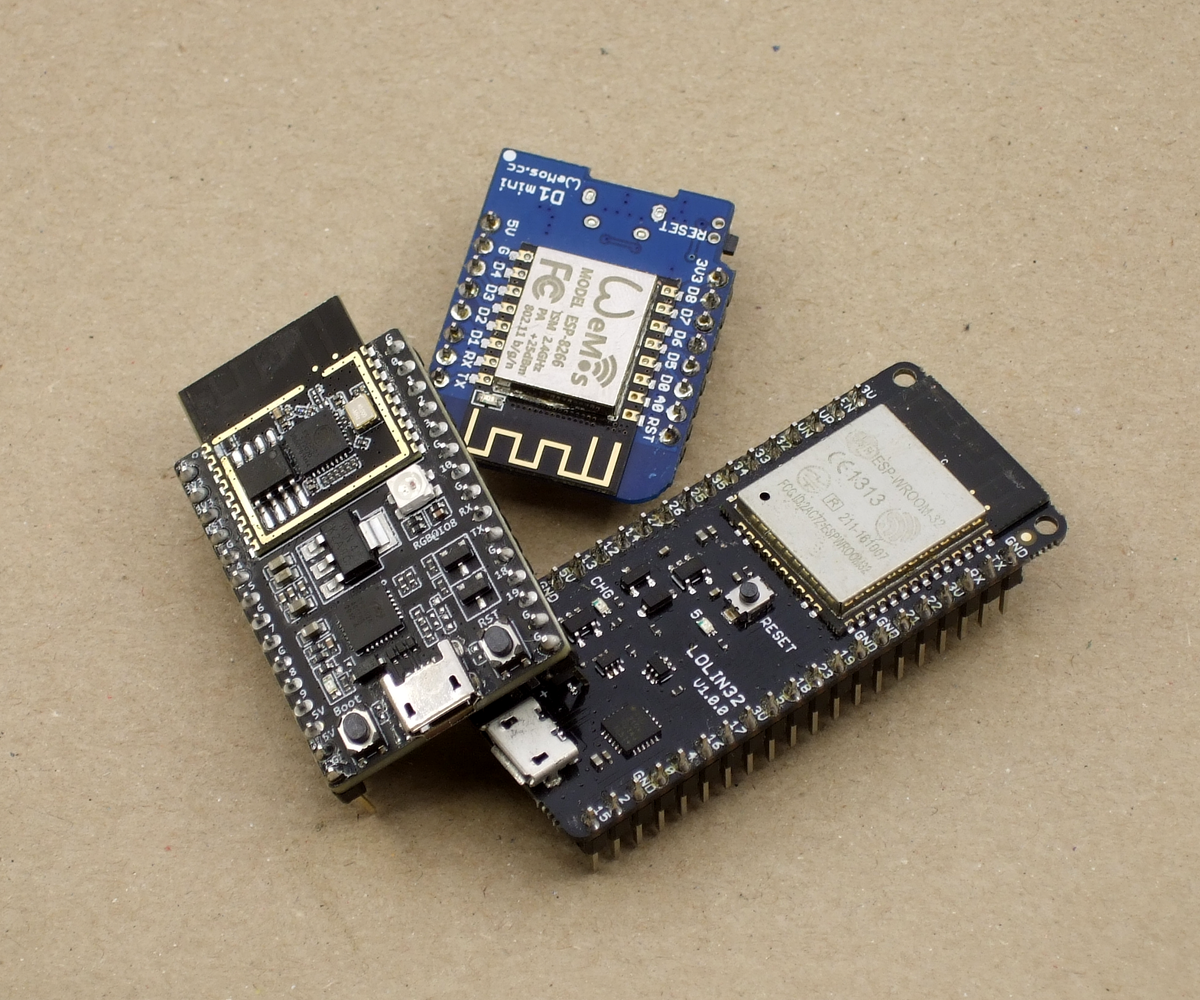
Instead, here we’re looking at the real-life performance of three different modules: the WeMos D1 mini for the ESP8266, the Lolin 32 for the ESP32, and our demo ESP32-C3-DevKitC-1, straight from Espressif. All were running with LEDs off, or clipped summarily with side-cutters in the case of the ESP32-C3 unit. (It didn’t make all that much difference, but you don’t know until you try.)
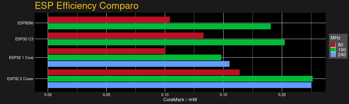
With power consumption data, we could also check out the modules’ power efficiency, measured in CoreMark score per milliwatt. Here, the ESP32-C3 does a bit better than the ESP8266, and somewhere between the ESP32 running one core and two cores respectively. This confirms what we’ve suspected for a while — if you want to save power, your best bet is to keep the chip sleeping as much as possible, and then run it full-out when it needs to run. If you’re doing that with an ESP32, use both cores.
And while our results are definitely significant and repeatable in terms of power and speed, they’re not game-changing. If we really needed to crush floats, we’d go for a chip that’s better suited for the task like an STM32F4xx or STM32F7xx, or those brutal NXP/Freescale 600 MHz i.MX ARM7 chips in the Teensy 4.0. If you’re buying an ESP-anything, it’s because you want the wireless connectivity, and it’s good to know that you’re not giving anything away with the ESP32-C3 on the CPU speed.
We hinted at it in the introduction, but the RISC-V nature of this chip, at least in terms of user experience, is no big deal. You code, compile, and flash just the same as you would with any other toolchain. The ESP-IDF makes using the new chip as easy as typing idf.py set-target esp32c3 and maybe idf.py fullclean for good measure. Then you go about your business. I must have swapped architectures 30 times in the course of this testing, and it’s literally that simple.
Of Peripherals and Pins
The first limitation you run into with an ESP8266 is that it doesn’t have enough GPIOs, or ADCs, for your particular project. While the ESP32 is a serious improvement in sheer GPIO quantity, once you’ve taken account of the pins with dedicated functions, or that are only input, you can end up pushing the limits of the chip easily. So you design in an external ADC chip and connect it via I2C, or you tack on a shift register and drive it with the blindingly fast I2S peripheral — something you can’t do with the ESP8266.
Sharing the peripheral set with the ESP32 will help alleviates some of these woes on the ESP32-C3, even though it has the same number of pins as the ESP8266. Heck, if you’re willing to allocate them, the C3 even has JTAG capabilities. And while the JTAG isn’t, a lot of the hardware peripherals are assignable to whichever pins you wish.
But we have to conclude that designing with the ESP32-C3 is still going to be a lot like designing for the ESP8266. I/O is limited. You’ll have to work with that.
Situating the ESP-C3
The ESP8266 started life as a simple AT-command-set WiFi modem, and a bunch of hackers proved that it had a lot more to offer. It’s sometimes hard to remember how difficult and expensive WiFi connectivity was before the ESP8266, but at the time, WiFi for $5 was revolutionary compared to WiFi for $50 – $100. Flash forward a few years, and the ESP32 is a competent microcontroller in its own right, with some cool quirky features. Oh yeah, and WiFi and BLE. We’ve come a long way in a very short time.
The C3 is really a blend of the two: a limited number of GPIO pins like the ESP8266, but with nice peripherals like the ESP32. If it’s priced to compete with the ESP8266, it will push that chip into retirement. But maybe it’s time.
The ESP-IDF has grown on us, but it’s still nothing compared to the overabundance of examples for ESP-Arduino or the incredible ease of use of MicroPython. When the latter gets ported over to the ESP32-C3, with its significantly expanded memory over the ESP8266, that’ll be a tremendously inexpensive platform that will make many forsake ever compiling again. But when you need the speed of the native SDK, it’s nice to be able to lean on the extant ESP32 codebase, so an ESP8266 in ESP32’s clothing is a winner.
We’ve got pre-production samples, and Espressif is still working on supporting all the features of the ESP32-C3 in the IDF. Heck, you can’t buy an ESP32-C3 module yet anyway, so we’re stuck looking into our crystal ball a little bit. But the murmurs about pricing similarly to the ESP8266 make us take notice, and it’s certainly a worthy upgrade even at a small price premium, if that’s what the market will bear. At the same time, the ESP32-C3 is fundamentally less capable than the ESP32, so it’s got to come in cheaper than that. With ESP8266 dev boards selling for $2 and ESP32 dev boards selling for $4, that doesn’t leave much wiggle room, and we suspect some folks will just pony up for the ESP32s. So it’s hard to say how much the price really matters anyway.
But it’s nice to see RISC-V cores in more devices, not least because the standardized instruction set architecture — which essentially amounts to a standard set of machine-language commands — makes writing optimizing compilers easier and faster. For the end user, it doesn’t matter all that much, but if saving money on IP licensing fees is what allows Espressif to include a more modern peripheral set for the ESP8266 price, then we’re all for it.