This Week in Security: Morse Code Malware, Literal and Figurative Watering Holes, and More

Code obfuscation has been around for a long time. The obfuscated C contest first ran way back in 1984, but there are examples of natural language obfuscation from way earlier in history. Namely Cockney rhyming slang, like saying “Lady from Bristol” instead of “pistol” or “lump of lead” instead of “head”. It’s speculated that Cockney was originally used to allow the criminal class to have conversations without tipping off police.

Code obfuscation in malware serves a similar purpose — hiding from security devices and applications. There are known code snippets and blacklisted IP addresses that anti-malware software scans for. If that known bad code can be successfully obfuscated, it can avoid detection. This is a bit of a constant game of cat-and-mouse, as the deobfuscation code itself eventually makes the blacklist. This leads to new obfuscation techniques, sometimes quite off the wall. Well this week, I found a humdinger of an oddball approach. Morse Code.

Yep, dots and dashes. The whole attack goes like this. You receive an email, claiming to be an invoice. It’s a .xlsx.hTML file. If you don’t notice the odd file extension, and actually let it open, you’re treated to a web page. The source of that page is a very minimal JS script that consists of a morse code decoder, and a payload encoded in Morse. In this case, the payload is simply a pair of external scripts that ask for an Office 365 login. The novel aspect of this is definitely the Morse Code. Yes, our own [Danie] covered this earlier this week, but it was too good not to mention here.

Literal Watering Hole Attack

You may have seen the breathless news articles, that a cyber bioterrorism attack almost poisoned a city. Let’s talk about what actually happened. The city in question has a population of under 15,000, and a dedicated water system. The primary control computer in the treatment plant legitimately had a remote access program installed on it. An unauthorized user used that remote access program from the outside early in the day, but only connected for a moment. This first access was assumed to be a legitimate use of the remote access system, but later in the day, it became obvious that something was afoot. When the system was accessed the second time, the remote user turned the sodium hydroxide level up, presumably to maximum, and logged back out.

Well it turns out that the Windows 7 machine in question was running TeamViewer, with a single password shared among all the city’s computers. Christopher Krebs suggests that a ticked-off employee is likely to blame, which is a decent guess.

Metaphorical Watering Hole Attack

These headlines write themselves, but this watering hole attack has quite a twist. We’ve covered problems like typosquatting and malicious project takeovers on platforms like pip and npm. [Alex Birsan] came up with a related attack he calls “Dependency Confusion“. The inspiration was finding PayPal code that wasn’t intended for public release on Github. What intrigued him about this code was the list of dependencies, some of which were open source packages on npm, while some were clearly proprietary packages. This mix brings a question to mind. If a package was uploaded to npm with a name collision with a local package, which version would be used?

As an enterprising researcher, [Alex] decided to find out. He does make the important caveat that he has authorization to do live penetration testing on all his targets, either through the terms of public bounty programs, or through private agreements. Without that authorization, trying to pull off an attack like this could land you in serious hot water.

So what happens when a build system requests a package that exists both locally and on a public repository? It depends, but in many cases, the package with the higher version number is used. [Alex] pulled information on proprietary package names from every source he could find, and carefully crafted proof-of-concept packages. To collect the list of successes, the spoofed packages exfiltrated a few bytes of data encoded over a DNS request. The roster of companies that were vulnerable to the attack is impressive, as is the amount of payout. Apple, Paypal, and Shopify all confirmed the efficacy of the technique, and paid out a cool $30,000 bounty each. Sometimes it’s very good to be a security researcher.

All Your Barcode Are Belong to Us

It’s no great surprise that barcode scanners are popular cell phone apps. You have a handheld computer with a camera and an internet connection. Pointing at a barcode and getting instant information about the product is potentially invaluable. One of the very popular barcode scanner apps on Android, with over ten million installs, has recently started a very aggressive adware campaign. The publisher of that app was LavaBird LTD.

Once the bad behavior was noticed, the app was pulled from the play store. This doesn’t remove it from devices, so you might check your devices for any LavaBird software. The Malwarebytes blog points out that sometimes malicious activity like this is a result of a third-party advertising library, and not the fault of the app developer. In this case, the bad code was directly in the app itself, signed by the developer’s key, and obfuscated to be hard to detect. All in all, the situation is reminiscent of the Great Suspender debacle we covered last week. It makes me suspect that something similar happened. Likely, the original app author sold to a shady third party, who filled the app with malware.

Noteworthy Notes

Firefox released 85.0.1 about a week ago, and there is an interesting note in the changelog: “Prevent access to NTFS special paths that could lead to filesystem corruption.” This rather cryptic note is a reference to bug 1689598, which is still restricted as of time of writing. We can get a look at the changelog that fixes the issue. Apparently there was a way to invoke a special file handler like $MFT or $Volume when opening a file. A malicious invocation can result in filesystem corruption, hence a potentially serious denial of service attack.

Remember the sudoedit bug from a couple weeks ago? A few vendors, namely Apple, considered themselves immune to the bug, since they didn’t have the sudoedit symlink. It didn’t take long for the internet to figure out that it is simple enough to create the symlink yourself, and then trigger the bug.

Google seems to be already making good on their “Know, Prevent, Fix” initiative, publishing the Open Source Vulnerabilities database. Currently, the OSS-Fuzz project is the sole data source, but more are planned. The purpose seems to be a automatable data source for tracking down vulnerabilities. Time will tell what further tools will result from the KPF push.
source https://hackaday.com/2021/02/12/this-week-in-security-morse-code-malware-literal-and-figurative-watering-holes-and-more/

Bitbanged DVI On A Raspberry Pi RP2040 Microcontroller

When we first saw the Raspberry Pi Pico and its RP2040 microcontroller last month it was obvious that to be more than just yet another ARM chip it needed something special, and that appeared to be present in the form of its onboard PIO peripherals. We were eagerly awaiting how the community might use them to push the RP2040 capabilities beyond their advertised limits. Now [Luke Wren] provides us with an example, as he pushes an RP2040 to produce a DVI signal suitable to drive an HDMI monitor.

It shouldn’t be a surprise that the chip can be overclocked, however it’s impressive to find that it can reach the 252 MHz necessary to generate the DVI timing. With appropriate terminations it proved possible for the GPIO lines to mimic the differential signalling required by the spec. A PCB with the RP2040 and an HDMI socket was created, also providing a couple of PMOD connectors for expansion. All code and software can be found in a GitHub repository.

The result is a usable DVI output which though it is a relatively low resolution 640×480 pixels at 60 Hz is still a major advance over the usual composite video provided by microcontroller projects. With composite support on monitors becoming a legacy item it’s a welcome sight to see an accessible path to an HDMI or DVI output without using an FPGA.

Thanks [BaldPower] for the tip.

source https://hackaday.com/2021/02/12/bitbanged-dvi-on-a-raspberry-pi-rp2040-microcontroller/

PCB Mods Silence Voltage Warnings on the Pi 4

If you’ve ever pushed the needle a bit on your Raspberry Pi, there’s a good chance you’ve been visited by the dreaded lightning bolt icon. When it pops up on the corner of the screen, it’s a warning that the input voltage is dipping into the danger zone. If you see this symbol often, the usual recommendation is to get a higher capacity power supply. But experienced Pi wranglers will know that the board can still be skittish.

Sick of seeing this icon during his MAME sessions, [Majenko] decided to attack the problem directly by taking a close look at the power supply circuitry of the Pi 4. While the official schematics for everyone’s favorite single-board computer are unfortunately incomplete, he was still able to identify a few components that struck him as a bit odd. While we wouldn’t necessarily recommend you rush out and make these same modifications to your own board, the early results are certainly promising.

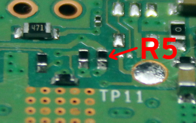
The first potential culprit [Majenko] found was a 10 ohm resistor on the 5 V line. He figured this part alone would have a greater impact on the system voltage than a dodgy USB cable would. The components aren’t labeled on the Pi’s PCB, but with a little poking of the multimeter he was able to track down the 0402 component and replace it with a tiny piece of wire. He powered up the Pi and ran a few games to test the fix, and while he definitely got fewer low-voltage warnings, there was still the occasional brownout.

Do we really need this part?

Going back to the schematic, he noticed there was a 10 uF capacitor on the same line as the resistor. What if he bumped that up a bit? The USB specifications say that’s the maximum capacitive load for a downstream device, but he reasoned that’s really only a problem for people trying to power the Pi from their computer’s USB port.

Tacking a 470 uF electrolytic capacitor to the existing SMD part might look a little funny, but after the installation, [Majenko] reports there hasn’t been a single low-voltage warning. He wonders if the addition of the larger capacitor might make removing the resistor unnecessary, but since he doesn’t want to mess with a good thing, that determination will be left as an exercise for the reader.

It’s no secret that the Raspberry Pi 4 has been plagued with power issues since release, but a newer board revision released last year helped smooth things out a bit. While most people wouldn’t go this far just to address the occasional edge case, it’s good to know folks are out there experimenting with potential fixes and improvements.

source https://hackaday.com/2021/02/12/pcb-mods-silence-voltage-warnings-on-the-pi-4/

PCB Mods Silence Voltage Warnings on the Pi 4

If you’ve ever pushed the needle a bit on your Raspberry Pi, there’s a good chance you’ve been visited by the dreaded lightning bolt icon. When it pops up on the corner of the screen, it’s a warning that the input voltage is dipping into the danger zone. If you see this symbol often, the usual recommendation is to get a higher capacity power supply. But experienced Pi wranglers will know that the board can still be skittish.

Sick of seeing this icon during his MAME sessions, [Majenko] decided to attack the problem directly by taking a close look at the power supply circuitry of the Pi 4. While the official schematics for everyone’s favorite single-board computer are unfortunately incomplete, he was still able to identify a few components that struck him as a bit odd. While we wouldn’t necessarily recommend you rush out and make these same modifications to your own board, the early results are certainly promising.

The first potential culprit [Majenko] found was a 10 ohm resistor on the 5 V line. He figured this part alone would have a greater impact on the system voltage than a dodgy USB cable would. The components aren’t labeled on the Pi’s PCB, but with a little poking of the multimeter he was able to track down the 0402 component and replace it with a tiny piece of wire. He powered up the Pi and ran a few games to test the fix, and while he definitely got fewer low-voltage warnings, there was still the occasional brownout.

Do we really need this part?

Going back to the schematic, he noticed there was a 10 uF capacitor on the same line as the resistor. What if he bumped that up a bit? The USB specifications say that’s the maximum capacitive load for a downstream device, but he reasoned that’s really only a problem for people trying to power the Pi from their computer’s USB port.

Tacking a 470 uF electrolytic capacitor to the existing SMD part might look a little funny, but after the installation, [Majenko] reports there hasn’t been a single low-voltage warning. He wonders if the addition of the larger capacitor might make removing the resistor unnecessary, but since he doesn’t want to mess with a good thing, that determination will be left as an exercise for the reader.

It’s no secret that the Raspberry Pi 4 has been plagued with power issues since release, but a newer board revision released last year helped smooth things out a bit. While most people wouldn’t go this far just to address the occasional edge case, it’s good to know folks are out there experimenting with potential fixes and improvements.

source https://hackaday.com/2021/02/12/pcb-mods-silence-voltage-warnings-on-the-pi-4/

PCB Mods Silence Voltage Warnings on the Pi 4

If you’ve ever pushed the needle a bit on your Raspberry Pi, there’s a good chance you’ve been visited by the dreaded lightning bolt icon. When it pops up on the corner of the screen, it’s a warning that the input voltage is dipping into the danger zone. If you see this symbol often, the usual recommendation is to get a higher capacity power supply. But experienced Pi wranglers will know that the board can still be skittish.

Sick of seeing this icon during his MAME sessions, [Majenko] decided to attack the problem directly by taking a close look at the power supply circuitry of the Pi 4. While the official schematics for everyone’s favorite single-board computer are unfortunately incomplete, he was still able to identify a few components that struck him as a bit odd. While we wouldn’t necessarily recommend you rush out and make these same modifications to your own board, the early results are certainly promising.

The first potential culprit [Majenko] found was a 10 ohm resistor on the 5 V line. He figured this part alone would have a greater impact on the system voltage than a dodgy USB cable would. The components aren’t labeled on the Pi’s PCB, but with a little poking of the multimeter he was able to track down the 0402 component and replace it with a tiny piece of wire. He powered up the Pi and ran a few games to test the fix, and while he definitely got fewer low-voltage warnings, there was still the occasional brownout.

Do we really need this part?

Going back to the schematic, he noticed there was a 10 uF capacitor on the same line as the resistor. What if he bumped that up a bit? The USB specifications say that’s the maximum capacitive load for a downstream device, but he reasoned that’s really only a problem for people trying to power the Pi from their computer’s USB port.

Tacking a 470 uF electrolytic capacitor to the existing SMD part might look a little funny, but after the installation, [Majenko] reports there hasn’t been a single low-voltage warning. He wonders if the addition of the larger capacitor might make removing the resistor unnecessary, but since he doesn’t want to mess with a good thing, that determination will be left as an exercise for the reader.

It’s no secret that the Raspberry Pi 4 has been plagued with power issues since release, but a newer board revision released last year helped smooth things out a bit. While most people wouldn’t go this far just to address the occasional edge case, it’s good to know folks are out there experimenting with potential fixes and improvements.

source https://hackaday.com/2021/02/12/pcb-mods-silence-voltage-warnings-on-the-pi-4/

GME-Tracking Rocketship For The Diamond-Handed Traders

If you’ve been on the internet lately, you’ve been bombarded by stories about retail traders attempting to beat Wall Street at their own game by trying to force a short squeeze on GameStop stock. It’s inspired memes, songs, and all manner of political discourse, along with this cute stock-tracking device built by [dickdemodickmarcinko].

The device is based on the typical exhortation that a given stock or cryptocurrency is going “to the moon”, i.e. skyrocketing upwards to great heights. IT consists of an ESP8266 in a 3D printed housing, with a HD44780 alphanumeric LCD displaying the GME stock price and percentage change over time. The microcontroller also controls a stepper motor, which rotates a 3D-printed rocketship up or down relative to the stock’s price changes. If it’s pointing straight up, prospects are good for those holding the stock!

Whether or not the GME squeeze happens, the build is a fun way to learn about electronics and the stock market at the same time, and could be readily repurposed to track other markets in future. We’ve featured other price trackers before, like this traffic light keeping an eye on Bitcoin. Video after the break.

source https://hackaday.com/2021/02/11/gme-tracking-rocketship-for-the-diamond-handed-traders/

GME-Tracking Rocketship For The Diamond-Handed Traders

If you’ve been on the internet lately, you’ve been bombarded by stories about retail traders attempting to beat Wall Street at their own game by trying to force a short squeeze on GameStop stock. It’s inspired memes, songs, and all manner of political discourse, along with this cute stock-tracking device built by [dickdemodickmarcinko].

The device is based on the typical exhortation that a given stock or cryptocurrency is going “to the moon”, i.e. skyrocketing upwards to great heights. IT consists of an ESP8266 in a 3D printed housing, with a HD44780 alphanumeric LCD displaying the GME stock price and percentage change over time. The microcontroller also controls a stepper motor, which rotates a 3D-printed rocketship up or down relative to the stock’s price changes. If it’s pointing straight up, prospects are good for those holding the stock!

Whether or not the GME squeeze happens, the build is a fun way to learn about electronics and the stock market at the same time, and could be readily repurposed to track other markets in future. We’ve featured other price trackers before, like this traffic light keeping an eye on Bitcoin. Video after the break.

source https://hackaday.com/2021/02/11/gme-tracking-rocketship-for-the-diamond-handed-traders/

GME-Tracking Rocketship For The Diamond-Handed Traders

If you’ve been on the internet lately, you’ve been bombarded by stories about retail traders attempting to beat Wall Street at their own game by trying to force a short squeeze on GameStop stock. It’s inspired memes, songs, and all manner of political discourse, along with this cute stock-tracking device built by [dickdemodickmarcinko].

The device is based on the typical exhortation that a given stock or cryptocurrency is going “to the moon”, i.e. skyrocketing upwards to great heights. IT consists of an ESP8266 in a 3D printed housing, with a HD44780 alphanumeric LCD displaying the GME stock price and percentage change over time. The microcontroller also controls a stepper motor, which rotates a 3D-printed rocketship up or down relative to the stock’s price changes. If it’s pointing straight up, prospects are good for those holding the stock!

Whether or not the GME squeeze happens, the build is a fun way to learn about electronics and the stock market at the same time, and could be readily repurposed to track other markets in future. We’ve featured other price trackers before, like this traffic light keeping an eye on Bitcoin. Video after the break.

source https://hackaday.com/2021/02/11/gme-tracking-rocketship-for-the-diamond-handed-traders/

Nanotube Yarn Makes Strong Bionic Muscles

What’s just a bit thicker than a human hair and has ten times the capability of a human muscle? Polymer-coated carbon nanotube yarn. Researchers at the University of Texas at Dallas created this yarn using carbon nanotubes coated with a polymer and coiled with a diameter of about 140 microns.

Passing a voltage through the fiber causes the muscle yarn to expand or contract. Previous similar fibers have to do both actions. That is, they expand and then contract in a bipolar movement. The polymer coating allows for unipolar fibers, critical to using the fibers as artificial muscles.

Another improvement is the development of a solid electrolyte so the fibers don’t have to float in a liquid bath. The researchers say this is important for the creating of smart fabrics and, of course, the material has obvious applications in any sort of robotic design. In addition to smart clothing, medical implants and prosthetics could benefit from this material, too.

The only problem, of course, is production at scale. It is one thing to make a few centimeters of yarn in a lab, and another to smart shirts in every big box store in the world.

This isn’t the first time we’ve seen this university toying with artificial muscles and carbon nanotubes. Some artificial muscle fibers need a laser, but that’s not very handy.

source https://hackaday.com/2021/02/11/nanotube-yarn-makes-strong-bionic-muscles/

PC Overclocking with an Air Conditioner

We never insist that a hack be practical. [Tech Ingredients] is living proof as they modded a computer case to use a window air conditioner for overclocking a computer. They think they haven’t hit the ceiling yet, and got their AMD Ryzen 8-core processor up to 4.58 GHz.

An advantage of forcing air from an air conditioner is that the air forced into the system is quite dry and clean. The trick is to create a simple duct to attach to a 5,000 BTU air conditioner. It doesn’t actually interface with the CPU cooling block, instead it just forces cool air into the case and this tends to cool everything inside. Admittedly, it isn’t any worse than plunging your computer in liquid nitrogen, and we’ll admit that air conditioning units are made to keep large areas cold and work at high duty cycles. With the air conditioning running, they disconnected at least some of the stock fans. The temperatures stayed cool even at high speeds.

We really liked the thermal interface test rig, which they used to test interface media. We wondered though, if you could tap into the cooling loop and actually push refrigerant through a water cooling block. An alternative would be to use a double loop as a nuclear reactor does, with a water loop on the CPU and the refrigerant loop in the air conditioner. Still, the way they did it has the advantage of being simple and reversible.

This is making us think about just 3D printing a faceplate for our air conditioner to hold a few Raspberry PI boards. Cheaper than a Dewar flask.

source https://hackaday.com/2021/02/11/pc-overclocking-with-an-air-conditioner/

Vacuum Forming Key Cap Covers Doesn’t Quite Work Out

Retrocomputing is as much about physical preservation as it is about electronics and computer science. Plastic is an awful material when it comes to decade-long timescales, and the forces of sun, air and water are unrelenting on these materials. [Drygol] has long experimented with techniques to preserve and refresh keycaps, and decided to try some fun vacuum forming techniques for something new. It sadly didn’t go to plan, however.

The basic idea was to use a vacuum-forming machine to coat keycaps in a thin layer of translucent plastic, for both aesthetic benefit and to preserve them from falling apart. Initial small-scale tests were promising, creating a key with a tight, form-fitting blue plastic wrap through which the original labels were still visible.

However, scaling up the process proved fraught. Uneven heating of the plastic film and a lack of rigidity in the carriage used to stretch it over the keycaps led to poor results. The final product showed many wrinkles and was distinctly unappealing.

[Drygol] isn’t giving up however, and plans to build a new vacuum table with greater performance. We can imagine this technique being an accessible way to colorize keycaps for a vintage cyberdeck or chiptune rig, without permanently modifying the keys. If you’ve got the inside knowledge on how to make this work, sound off in the comments.

We’ve seen [Drygol]’s work in this space before, too, like this extreme modded Amiga. If you’re executing your own retro repairs, be sure to drop us a line!

source https://hackaday.com/2021/02/11/vacuum-forming-key-cap-covers-doesnt-quite-work-out/

AOI By DIY

As anyone who has ever assembled a run of PCBs will tell you, quality inspection of solder joints can be a difficult process. Even under a microscope their appearances can be deceptive, and one silver blob can be perfect while its neighbour conceals a problem. The electronics industry have developed inspection tools to help, including optical inspection devices. It’s one of these that [Sina Roughani] has built, in the form of a hemispherical 3D printed dome with concentric rings of coloured LEDs mounted within it.

The principle behind this tool is as unexpected and simple as it is clever; by having different colours of light from different elevations of the dome it ensures that each different angle of the solder joint surface reflects a different colour. Thus a colour photograph shot from directly above the board allows visual inspection of the quality of the solder joints by the rainbow of colours that appears around their edges. This process can even be automated with OpenCV or similar, hence the process is referred to as Automated Optical Inspection, or AOI.
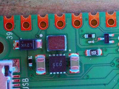
The technique is demonstrated with some pictures of a Raspberry Pi Pico, on which it shows really well the rainbow-edged solder joints and the red colour reflected from flat pads. What at first might seem like a novelty lighting effect becomes a very useful inspection tool.

PCB inspection is a subject we’ve covered before, though perhaps we don’t all have access to X-rays.

source https://hackaday.com/2021/02/11/aoi-by-diy/

Linux Fu: Serial Untethered

Serial ports used to be everywhere. In a way, they still are since many things that appear to plug in as a USB device actually look like a serial port. The problem is that today, the world runs on the network. Sure, you can buy a terminal server that converts a serial port to an Ethernet port, but what fun is that? In this article, I’m going to show you how to stream serial ports over the network using some available Linux tools. It isn’t perfect, and it won’t work for every case, but when it works it works well.

Everything is a File, Until it Isn’t

At some point in the past, Unix — the progenitor of Linux — treated virtually everything as a file, and all files were created more or less equal. Programs didn’t care if a file was local, on the network, from a tape drive, or arriving over a named pipe.

But things started to change. Even though a serial port is just a file under Linux, it has some special attributes that let you set, for example, baud rates. Worse, some programs “know” too much about files and insist on certain naming conventions. So, in theory, you should be able to create a network socket, connect one end to a serial port and the other end to a program, and be done with it. In theory.

The practice is different, of course. That might work in some very simple cases. You can use a utility called socat (like cat for a socket) to set it up. However, if the program you are trying to fake tries to set a baud rate, for example, it is probably going to throw up its hands. Some programs won’t even recognize your fake serial port.

About socat

The socat program is like a magic adapter cable that simply pipes everything from one place to another and also handles the reverse traffic. The program can read from files, pipes, devices, sockets, and a few other items. For example, you might want to build a simple TCP proxy to forward connections on the local host to another host. That’s easy with socat:

socat TCP4-LISTEN:88 TCP4:10.1.1.125:8000

That will only handle one connection, but you can even ask socat to fork off a new connection to handle multiple requests.

The Problem

If you try doing this with a serial port, though, it is unlikely to work without a lot of setup. This is such a common desire that there are several programs available to help. Most Linux distributions will support ser2net, a program made to handle the task of converting a serial port to a socket. If ser2net doesn’t suit you, there’s also some Python code that ships as an example with the pyserial library, but your distribution version of pyserial maybe too old to support it. If that’s the case, you’ll need to install it outside of your package manager using pip, for example. I’m going to assume you are using ser2net.

The ser2net program normally installs as a system service and you can  edit /etc/ser2net.conf to configure it. I took out all the default lines and added the two serial ports I wanted to expose along with the baud rates I wanted:

7777:telnet:0:/dev/ttyUSB0:115200 8DATABITS NONE 1STOPBIT remctl
7778:telnet:0:/dev/ttyUSB1:115200 8DATABITS NONE 1STOPBIT remctl

Then you’ll need to restart the service (probably systemctl restart ser2net; if it fails to restart the first time, try again as sometimes it tries to start before the old copy is totally shutdown).

For debugging, you might want to stop the service and run with some debugging messages:

ser2net -d -C "7778:telnet:0:/dev/ttyUSB1:115200 8DATABITS NONE 1STOPBIT remctl"

Either way, once the service is running, the ports you specify (7777 and 7778 in my configuration file) will act like the associated serial ports.

A few notes. If you are doing this with a 3D printer and you have something like Octoprint running, you’ll need to shut it down or otherwise make it let go of the printer port before you set all this up. This would be true of any program that would hold the serial port you are interested in opening. For some standard ports, you need to make sure login is not holding the port open and waiting for a user. Exactly how all that works will depend on your setup. The same goes for your firewall. If you are listening on port 7777 and you use a firewall, you’ll need to set it up to allow connections on that port. Don’t forget you usually have to be root to open up low-numbered ports, too.

The Client Side

On the client side, you can use socat, but some programs will figure out it isn’t a real serial port. You can still, try though:

socat pty,link=$HOME/dev/ttyNET0,waitslave tcp:10.1.1.125:7777

Some programs are only going to look for devices in /dev, though. If that’s the case for you, you are going to need to run socat as root (use sudo) and then also set /dev/ttyNET0 so that you have read and write permissions (e.g., sudo chmod 666 /dev/ttyNET0).

Testing 1, 2, 3…

Instead of trying your program right away, though, I suggest you test using something like picocom. For example, on the client machine after you run socat, you should be able to run something like:

picocom -b 115200 $HOME/dev/ttyNET0
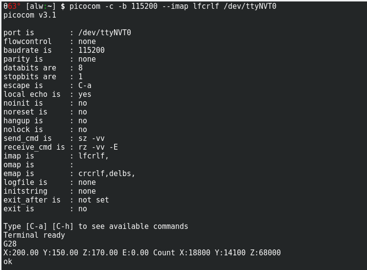
Picocom can talk across the network using a virtual serial device

Obviously, you’ll need to use the right name and baud rate. You should be able to talk to the remote device. If not, figure out why before you run the regular program. If your serial device isn’t text-based, you might have more luck with cutecom but, alas, the program knows your fake serial port is fake and won’t let you select it. On the other hand, the program is open source, so you could easily create a local version that used any device name you like. There are other choices, of course. For example, gtkterm will let you pick up the fake serial port.

If you run into a protocol error, you may find that the serial port has moved (e.g., it was /dev/ttyUSB0 and now it is /dev/ttyUSB1) or you have an invalid baud rate. The error message isn’t very helpful, but don’t forget to use the -d option in ser2net while troubleshooting.

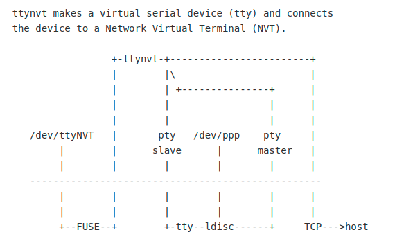
The ttynvt program doesn’t have great documentation graphics, but they are accurate.

When you do run the regular program, it might work. However, it also might throw an error or, in some cases, refuse to let you select the file because it isn’t really a serial port. In some cases, you are simply out of luck. However, a smarter client that understands the serial port might help, too. The ttynvt program is one example of that. You will probably have to build it from source, but it is very easy to do that. it does depend on libfuse, but otherwise doesn’t need anything exotic.

Once you have it built, try something like this:

sudo src/ttynvt -M 199 -m 6 -n ttyNET0 -S 10.1.1.125:7777

This will create the /dev/ttyNET0 device (so you need to be root). On my system, the new device had read and write permissions set for root and the dialout group. You might need to check and fix the permissions, though, depending on your setup.

Again, test with picocom, and then try your target program. Cross your fingers!

Why, Oh Why?

My original goal was to run Lightburn software for my laser cutter on a big machine using a remote desktop. I wanted the laser cutter plugged into the USB port on the local machine and have the software talk to a fake port on the bigger computer.

Alas, as of today, Lighburn is too smart for my naughty tricks and refuses to show my virtual serial ports. There’s no way that I know of to force it to use a file name of my choice, so I can’t even try to see if it would work. However, I was able to test the setup with some other G code software and it does work. I’ve mentioned this to Lightburn, so maybe it will be fixed by the time you read this.

The paradigm that “everything is a file” is very powerful. Unfortunately, every year it gets less true and that causes more hoops to jump through when you want to do something interesting like this. Still, in true Linux fashion, there’s always a way to get there. I have no doubt that I could trace the calls Lighburn is making to open the port and find a way to fake them for the serial client. I’m hoping, though, that I don’t have to.

source https://hackaday.com/2021/02/11/linux-fu-serial-untethered/

Linux Fu: Serial Untethered

Serial ports used to be everywhere. In a way, they still are since many things that appear to plug in as a USB device actually look like a serial port. The problem is that today, the world runs on the network. Sure, you can buy a terminal server that converts a serial port to an Ethernet port, but what fun is that? In this article, I’m going to show you how to stream serial ports over the network using some available Linux tools. It isn’t perfect, and it won’t work for every case, but when it works it works well.

Everything is a File, Until it Isn’t

At some point in the past, Unix — the progenitor of Linux — treated virtually everything as a file, and all files were created more or less equal. Programs didn’t care if a file was local, on the network, from a tape drive, or arriving over a named pipe.

But things started to change. Even though a serial port is just a file under Linux, it has some special attributes that let you set, for example, baud rates. Worse, some programs “know” too much about files and insist on certain naming conventions. So, in theory, you should be able to create a network socket, connect one end to a serial port and the other end to a program, and be done with it. In theory.

The practice is different, of course. That might work in some very simple cases. You can use a utility called socat (like cat for a socket) to set it up. However, if the program you are trying to fake tries to set a baud rate, for example, it is probably going to throw up its hands. Some programs won’t even recognize your fake serial port.

About socat

The socat program is like a magic adapter cable that simply pipes everything from one place to another and also handles the reverse traffic. The program can read from files, pipes, devices, sockets, and a few other items. For example, you might want to build a simple TCP proxy to forward connections on the local host to another host. That’s easy with socat:

socat TCP4-LISTEN:88 TCP4:10.1.1.125:8000

That will only handle one connection, but you can even ask socat to fork off a new connection to handle multiple requests.

The Problem

If you try doing this with a serial port, though, it is unlikely to work without a lot of setup. This is such a common desire that there are several programs available to help. Most Linux distributions will support ser2net, a program made to handle the task of converting a serial port to a socket. If ser2net doesn’t suit you, there’s also some Python code that ships as an example with the pyserial library, but your distribution version of pyserial maybe too old to support it. If that’s the case, you’ll need to install it outside of your package manager using pip, for example. I’m going to assume you are using ser2net.

The ser2net program normally installs as a system service and you can  edit /etc/ser2net.conf to configure it. I took out all the default lines and added the two serial ports I wanted to expose along with the baud rates I wanted:

7777:telnet:0:/dev/ttyUSB0:115200 8DATABITS NONE 1STOPBIT remctl
7778:telnet:0:/dev/ttyUSB1:115200 8DATABITS NONE 1STOPBIT remctl

Then you’ll need to restart the service (probably systemctl restart ser2net; if it fails to restart the first time, try again as sometimes it tries to start before the old copy is totally shutdown).

For debugging, you might want to stop the service and run with some debugging messages:

ser2net -d -C "7778:telnet:0:/dev/ttyUSB1:115200 8DATABITS NONE 1STOPBIT remctl"

Either way, once the service is running, the ports you specify (7777 and 7778 in my configuration file) will act like the associated serial ports.

A few notes. If you are doing this with a 3D printer and you have something like Octoprint running, you’ll need to shut it down or otherwise make it let go of the printer port before you set all this up. This would be true of any program that would hold the serial port you are interested in opening. For some standard ports, you need to make sure login is not holding the port open and waiting for a user. Exactly how all that works will depend on your setup. The same goes for your firewall. If you are listening on port 7777 and you use a firewall, you’ll need to set it up to allow connections on that port. Don’t forget you usually have to be root to open up low-numbered ports, too.

The Client Side

On the client side, you can use socat, but some programs will figure out it isn’t a real serial port. You can still, try though:

socat pty,link=$HOME/dev/ttyNET0,waitslave tcp:10.1.1.125:7777

Some programs are only going to look for devices in /dev, though. If that’s the case for you, you are going to need to run socat as root (use sudo) and then also set /dev/ttyNET0 so that you have read and write permissions (e.g., sudo chmod 666 /dev/ttyNET0).

Testing 1, 2, 3…

Instead of trying your program right away, though, I suggest you test using something like picocom. For example, on the client machine after you run socat, you should be able to run something like:

picocom -b 115200 $HOME/dev/ttyNET0
Picocom can talk across the network using a virtual serial device

Obviously, you’ll need to use the right name and baud rate. You should be able to talk to the remote device. If not, figure out why before you run the regular program. If your serial device isn’t text-based, you might have more luck with cutecom but, alas, the program knows your fake serial port is fake and won’t let you select it. On the other hand, the program is open source, so you could easily create a local version that used any device name you like. There are other choices, of course. For example, gtkterm will let you pick up the fake serial port.

If you run into a protocol error, you may find that the serial port has moved (e.g., it was /dev/ttyUSB0 and now it is /dev/ttyUSB1) or you have an invalid baud rate. The error message isn’t very helpful, but don’t forget to use the -d option in ser2net while troubleshooting.

The ttynvt program doesn’t have great documentation graphics, but they are accurate.

When you do run the regular program, it might work. However, it also might throw an error or, in some cases, refuse to let you select the file because it isn’t really a serial port. In some cases, you are simply out of luck. However, a smarter client that understands the serial port might help, too. The ttynvt program is one example of that. You will probably have to build it from source, but it is very easy to do that. it does depend on libfuse, but otherwise doesn’t need anything exotic.

Once you have it built, try something like this:

sudo src/ttynvt -M 199 -m 6 -n ttyNET0 -S 10.1.1.125:7777

This will create the /dev/ttyNET0 device (so you need to be root). On my system, the new device had read and write permissions set for root and the dialout group. You might need to check and fix the permissions, though, depending on your setup.

Again, test with picocom, and then try your target program. Cross your fingers!

Why, Oh Why?

My original goal was to run Lightburn software for my laser cutter on a big machine using a remote desktop. I wanted the laser cutter plugged into the USB port on the local machine and have the software talk to a fake port on the bigger computer.

Alas, as of today, Lighburn is too smart for my naughty tricks and refuses to show my virtual serial ports. There’s no way that I know of to force it to use a file name of my choice, so I can’t even try to see if it would work. However, I was able to test the setup with some other G code software and it does work. I’ve mentioned this to Lightburn, so maybe it will be fixed by the time you read this.

The paradigm that “everything is a file” is very powerful. Unfortunately, every year it gets less true and that causes more hoops to jump through when you want to do something interesting like this. Still, in true Linux fashion, there’s always a way to get there. I have no doubt that I could trace the calls Lighburn is making to open the port and find a way to fake them for the serial client. I’m hoping, though, that I don’t have to.

source https://hackaday.com/2021/02/11/linux-fu-serial-untethered/

Linux Fu: Serial Untethered

Serial ports used to be everywhere. In a way, they still are since many things that appear to plug in as a USB device actually look like a serial port. The problem is that today, the world runs on the network. Sure, you can buy a terminal server that converts a serial port to an Ethernet port, but what fun is that? In this article, I’m going to show you how to stream serial ports over the network using some available Linux tools. It isn’t perfect, and it won’t work for every case, but when it works it works well.

Everything is a File, Until it Isn’t

At some point in the past, Unix — the progenitor of Linux — treated virtually everything as a file, and all files were created more or less equal. Programs didn’t care if a file was local, on the network, from a tape drive, or arriving over a named pipe.

But things started to change. Even though a serial port is just a file under Linux, it has some special attributes that let you set, for example, baud rates. Worse, some programs “know” too much about files and insist on certain naming conventions. So, in theory, you should be able to create a network socket, connect one end to a serial port and the other end to a program, and be done with it. In theory.

The practice is different, of course. That might work in some very simple cases. You can use a utility called socat (like cat for a socket) to set it up. However, if the program you are trying to fake tries to set a baud rate, for example, it is probably going to throw up its hands. Some programs won’t even recognize your fake serial port.

About socat

The socat program is like a magic adapter cable that simply pipes everything from one place to another and also handles the reverse traffic. The program can read from files, pipes, devices, sockets, and a few other items. For example, you might want to build a simple TCP proxy to forward connections on the local host to another host. That’s easy with socat:

socat TCP4-LISTEN:88 TCP4:10.1.1.125:8000

That will only handle one connection, but you can even ask socat to fork off a new connection to handle multiple requests.

The Problem

If you try doing this with a serial port, though, it is unlikely to work without a lot of setup. This is such a common desire that there are several programs available to help. Most Linux distributions will support ser2net, a program made to handle the task of converting a serial port to a socket. If ser2net doesn’t suit you, there’s also some Python code that ships as an example with the pyserial library, but your distribution version of pyserial maybe too old to support it. If that’s the case, you’ll need to install it outside of your package manager using pip, for example. I’m going to assume you are using ser2net.

The ser2net program normally installs as a system service and you can  edit /etc/ser2net.conf to configure it. I took out all the default lines and added the two serial ports I wanted to expose along with the baud rates I wanted:

7777:telnet:0:/dev/ttyUSB0:115200 8DATABITS NONE 1STOPBIT remctl
7778:telnet:0:/dev/ttyUSB1:115200 8DATABITS NONE 1STOPBIT remctl

Then you’ll need to restart the service (probably systemctl restart ser2net; if it fails to restart the first time, try again as sometimes it tries to start before the old copy is totally shutdown).

For debugging, you might want to stop the service and run with some debugging messages:

ser2net -d -C "7778:telnet:0:/dev/ttyUSB1:115200 8DATABITS NONE 1STOPBIT remctl"

Either way, once the service is running, the ports you specify (7777 and 7778 in my configuration file) will act like the associated serial ports.

A few notes. If you are doing this with a 3D printer and you have something like Octoprint running, you’ll need to shut it down or otherwise make it let go of the printer port before you set all this up. This would be true of any program that would hold the serial port you are interested in opening. For some standard ports, you need to make sure login is not holding the port open and waiting for a user. Exactly how all that works will depend on your setup. The same goes for your firewall. If you are listening on port 7777 and you use a firewall, you’ll need to set it up to allow connections on that port. Don’t forget you usually have to be root to open up low-numbered ports, too.

The Client Side

On the client side, you can use socat, but some programs will figure out it isn’t a real serial port. You can still, try though:

socat pty,link=$HOME/dev/ttyNET0,waitslave tcp:10.1.1.125:7777

Some programs are only going to look for devices in /dev, though. If that’s the case for you, you are going to need to run socat as root (use sudo) and then also set /dev/ttyNET0 so that you have read and write permissions (e.g., sudo chmod 666 /dev/ttyNET0).

Testing 1, 2, 3…

Instead of trying your program right away, though, I suggest you test using something like picocom. For example, on the client machine after you run socat, you should be able to run something like:

picocom -b 115200 $HOME/dev/ttyNET0
Picocom can talk across the network using a virtual serial device

Obviously, you’ll need to use the right name and baud rate. You should be able to talk to the remote device. If not, figure out why before you run the regular program. If your serial device isn’t text-based, you might have more luck with cutecom but, alas, the program knows your fake serial port is fake and won’t let you select it. On the other hand, the program is open source, so you could easily create a local version that used any device name you like. There are other choices, of course. For example, gtkterm will let you pick up the fake serial port.

If you run into a protocol error, you may find that the serial port has moved (e.g., it was /dev/ttyUSB0 and now it is /dev/ttyUSB1) or you have an invalid baud rate. The error message isn’t very helpful, but don’t forget to use the -d option in ser2net while troubleshooting.

The ttynvt program doesn’t have great documentation graphics, but they are accurate.

When you do run the regular program, it might work. However, it also might throw an error or, in some cases, refuse to let you select the file because it isn’t really a serial port. In some cases, you are simply out of luck. However, a smarter client that understands the serial port might help, too. The ttynvt program is one example of that. You will probably have to build it from source, but it is very easy to do that. it does depend on libfuse, but otherwise doesn’t need anything exotic.

Once you have it built, try something like this:

sudo src/ttynvt -M 199 -m 6 -n ttyNET0 -S 10.1.1.125:7777

This will create the /dev/ttyNET0 device (so you need to be root). On my system, the new device had read and write permissions set for root and the dialout group. You might need to check and fix the permissions, though, depending on your setup.

Again, test with picocom, and then try your target program. Cross your fingers!

Why, Oh Why?

My original goal was to run Lightburn software for my laser cutter on a big machine using a remote desktop. I wanted the laser cutter plugged into the USB port on the local machine and have the software talk to a fake port on the bigger computer.

Alas, as of today, Lighburn is too smart for my naughty tricks and refuses to show my virtual serial ports. There’s no way that I know of to force it to use a file name of my choice, so I can’t even try to see if it would work. However, I was able to test the setup with some other G code software and it does work. I’ve mentioned this to Lightburn, so maybe it will be fixed by the time you read this.

The paradigm that “everything is a file” is very powerful. Unfortunately, every year it gets less true and that causes more hoops to jump through when you want to do something interesting like this. Still, in true Linux fashion, there’s always a way to get there. I have no doubt that I could trace the calls Lighburn is making to open the port and find a way to fake them for the serial client. I’m hoping, though, that I don’t have to.

source https://hackaday.com/2021/02/11/linux-fu-serial-untethered/

Tiny Motors Enable Experimental Piano Performance

Just when you think you’ve seen every possible way to play the piano, [Alessandro Perini] came up with a new one. In this piece, written for the percussionist [Irene Bianco], hand-held motors become a tangible interface between composer, electronic music equipment, and the performer.

The performance involved ten small disc motors, held above the strings by a wooden frame. The motors are controlled by a Arduino Nano, which turns the motors on or off based on MIDI commands from a computer. However, the performance is not entirely automated. [Irene] wears a pair of contact microphones on her fingers, which she moves around inside the piano to capture the sounds of the strings vibrating in harmony with the motors themselves.

[Alessandro] has been kind enough to share a tutorial on how to recreate the hardware and software behind the performance for those keen to create similar work of their own. As with any musical endeavour, MIDI can always make it better. Video after the break.

source https://hackaday.com/2021/02/11/tiny-motors-enable-experimental-piano-performance/

Tesla Recalls Cars With eMMC Failures, Calls Part a ‘Wear Item’

Flash storage failures in the computer behind Tesla’s famous touch screen are causing headaches for drivers.

It’s a problem familiar to anyone who’s spent a decent amount of time playing with a Raspberry Pi – over time, the flash in the SD card reaches its write cycle limits, and causes a cavalcade of confusing errors before failing entirely. While flash storage is fast, compact, and mechanically reliable, it has always had a writeable lifespan much shorter than magnetic technologies.

Of course, with proper wear levelling techniques and careful use, these issues can be mitigated successfully. The surprising thing is when a major automaker fails to implement such basic features, as was the case with several Tesla models. Due to the car’s Linux operating system logging excessively to its 8 GB eMMC storage, the flash modules have been wearing out. This leads to widespread failures in the car, typically putting it into limp mode and disabling many features controlled via the touchscreen.

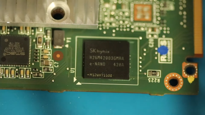
With the issue affecting important subsystems such as the heater, defroster, and warning systems, the NHTSA wrote to the automaker in January requesting a recall. Tesla’s response acquiesced to this request with some consternation, downplaying the severity of the issue. Now they are claiming that the eMMC chip, ball-grid soldered to the motherboard, inaccessible without disassembling the dash, and not specifically mentioned in the owner’s manual, should be considered a “wear item”, and thus should not be subject to such scrutiny.

Certainly An Odd Wear Item

The chip in question, a sub-$7 eMMC chip packing 8GB of storage.

Historically, major electronic parts in automobiles are not considered consumables. While it’s not uncommon for some cars to face issues with engine control units or body control modules, they’re not typically treated as wear items to be replaced at nominal intervals. Thus far, precedent has considered these parts as something to last the lifetime of the vehicle, and to be replaced in the case of unexpected malfunction. The Tesla case is different in that the eMMC failure is, by and large, inevitable. Rather than being a case of isolated malfunctions in a small percentage of cars as would be expected from the occasional manufacturing defect, this is a issue affecting every car that rolled off the line up to a certain date. Failure rates are up to 30 percent in certain build months. With the computer and touchscreen being in charge of so many vital vehicle functions, it’s not a defect that can be easily ignored by the end user.

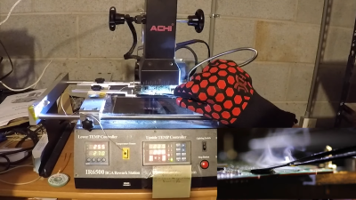
Replacing the chip involves reflowing the board, and carefully pulling off the offending part with tweezers.

Tesla’s assertion that the eMMC chip should be considered a ‘wear item’ is a dubious one at best. Flash memory does wear out, it’s true, as Tesla points out when discussing the limits of the technology. Many parts on a modern car wear out over time – brake pads, belts, and air filters are all common examples. The difference is that these parts are all designed to be replaced by the end user or a typical mechanic.

Trying to claim that a ball-grid array chip, permanently soldered onto a PCB and buried inside the dashboard is a wear item is patently ludicrous. If it were, we’d expect to see several things. There’d be a recommend time and mileage upon which the eMMC would be changed to avoid surprise failures, and this would be listed in the manual. Additionally, Tesla’s repair process would involve desoldering the eMMC chip from the board and replacing it directly. Given that Tesla are instead replacing the computers as a whole is indicative that the part is not being treated as a wear item by anyone, anywhere.

Obviously, the chip can be replaced, but it’s no easy job. Once the computer’s main board has been extracted from the car, the storage must be backed up over JTAG. Then, it must be carefully reflowed to remove the chip, in a delicate process that has a significant chance of damaging other components on the board. If the chip was a wear item, it wouldn’t require specialist BGA reflow equipment to change. We’d see Tesla doing it routinely, replacing a sub-$7 chip rather than swapping out entire mainboards instead at the costs of thousands of dollars. Granted, there are parts of modern cars that are also time consuming to replace – such as timing belts, water pumps, and so on. However, again, in these cases, automakers make it clear that these are wear items ahead of time, create maintenance schedules for them, and standard processes to change them.

Nobody would put up with swapping out their entire front suspension setup every time their brakes wore out – automakers realised brake pads were wear items and designed accordingly. Tesla simply dropped the ball, writing too often to the flash memory, which isn’t easily replaceable. The proper solution is trivial. Either stop logging so much to flash storage, or make it easier to swap out.

And maybe put the logs in their own partition. While SD cards probably aren’t up to snuff for storing the car’s operating system, they’d make a cheap place to store non-critical logs that probably are never read anyway. Alternatively, put the eMMC chip on a removable module, or just use an M.2 drive with automotive-rated connectors.

The issue is claimed to only effect models built prior to March 2018, which run on an NVIDIA Tegra 3. Later models are based on the Intel Atom, and feature a larger eMMC chip on board. These modules are yet to demonstrate the same failures, and Tesla claim they should not suffer the issue. We’ll see.


source https://hackaday.com/2021/02/11/tesla-recalls-cars-with-emmc-failures-calls-part-a-wear-item/

Restored Dreamcast is a SEGA Fan’s Dream Come True

[Bren Sutton] has been a long time fan of SEGA’s Dreamcast, eagerly snapping one up right around its October 1999 European release. But after decades of neglect, and a somewhat questionable paint job a decade or so back, he decided it was time to spruce his old friend up. He could have just cleaned the machine and been done with it, but he took the opportunity to revamp the console’s internals with both practical and cosmetic trickery.

The first step was getting the system looking a bit fresher. Removing the silver metallic paint he applied in his youth with a rattle can wasn’t going so well, so he ended up buying a broken donor console on eBay so he’d have a new shell to work with. The donor was yellowed with age, but a coating of peroxide cream and a few hours under a cheap UV light got it whitened up nicely. Now that he had a fresh new case, [Bren] turned his attention to the internal components.

Those who might be plugged into the active Dreamcast homebrew scene may already know that several upgrade modules exist for SEGA’s last home game console. One of the most popular replaces the optical drive with an SD card filled with your favorite game ISOs. You can also get a modern high efficiency power supply, as well as a board that replaces the original soldered-on clock battery with a slot that fits a CR2032. [Bren] threw them all in, ensuring several more years of gaming bliss.

But he wasn’t done yet. He also wanted to add some visual flair to his new and improved console. After some consideration, he carefully cut the logo out of the Dreamcast’s lid, and installed an Adafruit CLUE board underneath it. With a few carefully crafted GIFs installed onto the CircuitPython-powered board, the console now has a gorgeous fully animated logo that you can see in the video after the break.

[Bren] could have really taken his console to the next level by doubling its available RAM to an eye-watering 32 MB, but considering the limited software support for that particularly bodacious modification, we’ll let it slide.

source https://hackaday.com/2021/02/11/restored-dreamcast-is-a-sega-fans-dream-come-true/

a Hair-Raising Twist on Infinity Mirrors

Just when we thought we’d seen it all in the infinity mirror department, [FieldCrafting] blazed a tiny, shiny new trail with their electroplated infinity mirror hair pin. We’d sure like to stick this in our French twist. Fortunately, [FieldCrafting] provided step-by-step instructions for everything from the 3D printing to the copper electroplating to the mirror film and circuitry application.

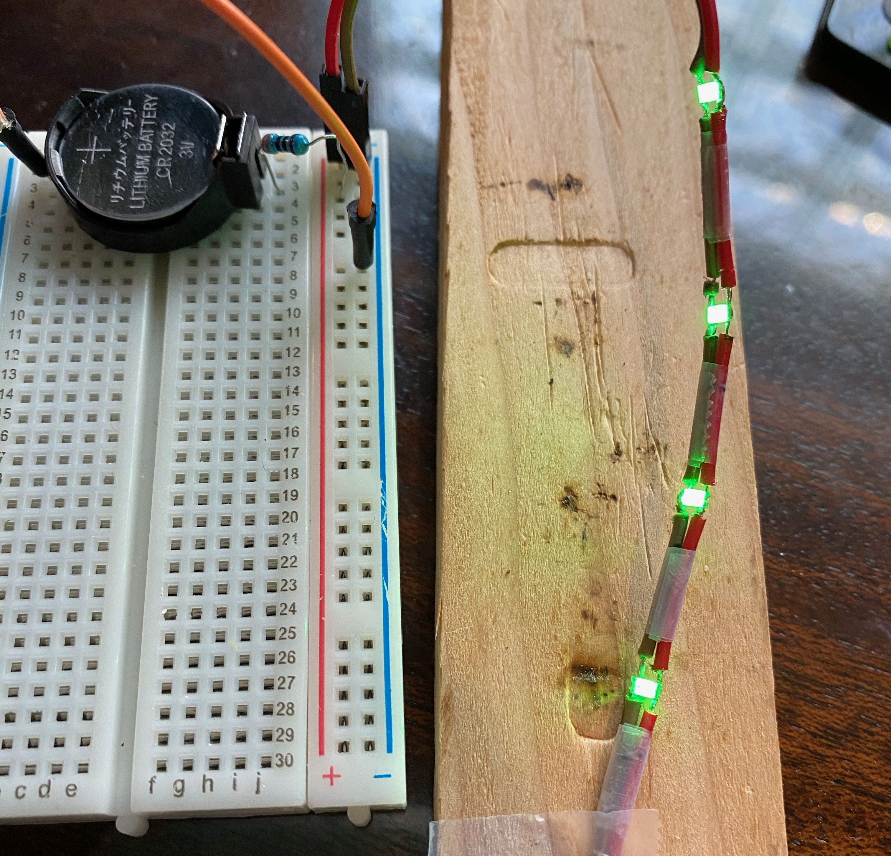
And what tiny circuitry it is! This pin is powered by a coin cell and even has a micro slider switch to conserve it. The stick parts are a pair of knitting needles, which is a great idea — they’re pointy enough to get through hair, but not so pointy that they hurt.

[FieldCrafting] was planning to solder 1206 LEDs to copper tape and line the cavity with it, but somehow the CAD file ended up with 0603, so there wasn’t enough space for two tape traces. We think it’s probably for the better — [FieldCrafting]’s solution was to use two-conductor wire, strategically stripped, which seems a lot less fiddly than trying to keep two bare tape traces separated and passing pixies.

Don’t have enough hair for one of these? Surely you could use some handsome infinity coasters to round out that home bar setup.

source https://hackaday.com/2021/02/10/a-hair-raising-twist-on-infinity-mirrors/

1938 Radio Has Awesome Dial

[Mr. Carlson] is truly an old radio surgeon. The evidence? He recently restored an 83-year-old DeForest radio by transplanting an identical chassis from another similar radio. The restoration is fun to watch, but the 7D832 radio dial looks amazing. The dial is very colorful and the wooden knobs and preset selector are beautiful. To seal the deal, the center of the dial has a magic eye tube, giving the radio a retro high tech look.

The donor chassis needed some work before the surgery. In addition, [Carlson] makes some improvements along the way. The radio showed signs of previous service work, which is not surprising after 83 years.

The preset dial is interesting and required two adjustments in the back of the radio. Each button had a limited range of frequencies. We suspect this was a pretty high-end radio in its day.

There are some interesting tubes in the radio including Canadian tubes with a metal spray-on shield. We will warn you: the video is about three and a half hours long. No kidding. There’s a lot to talk about. We know its a big investment of time, but if you are interested in old radios, there’s a lot here and a great opportunity to watch a pro restore a radio from start to finish.

We love the look and sound of these old radios. We’ll admit, not all of them are as pretty as this DeForest.

source https://hackaday.com/2021/02/10/1938-radio-has-awesome-dial/

Tonewheels Warble in This Organ-Inspired Musical Instrument

Younger readers may not recall the days when every mall had a music store — not the kind where tapes and LPs were sold, but the kind where you could buy instruments. These places inevitably had an employee belting out mall-music to all and sundry on an electric organ. And more often than not, the organist was playing a Hammond organ, with the distinct sound of these instruments generated by something similar to this tonewheel organ robot.

Tonewheels are toothed ferromagnetic wheels that are rotated near a pickup coil. This induces a current that can be amplified; alter the tooth profile or change the speed of rotation, and you’ve got control over the sounds produced. While a Hammond organ uses this technique to produce a wide range of sounds, [The Mixed Signal]’s effort is considerably more modest but nonetheless interesting. A stepper motor and a 1:8 ratio 3D-printed gearbox power a pair of shafts which each carry three different tonewheels. The tonewheels themselves are laser-cut from mild steel and range from what look like spur gears to wheels with but a few large lobes. This is a step up from the previous version of this instrument, which used tonewheels 3D-printed from magnetic filament.

Each tonewheel has its own pickup, wound using a coil winder that [TheMixed Signal] previously built. Each coil has a soft iron core, allowing for the addition of one or more neodymium bias magnets, which dramatically alters the tone. The video below shows the build and a demo; skip ahead to 16:10 or so if you just want to hear the instrument play. It’s — interesting. But it’s clearly a work in progress, and we’re eager to see where it goes.

source https://hackaday.com/2021/02/10/tonewheels-warble-in-this-organ-inspired-musical-instrument/

3D Printed Turbocharger Boosts Pulsejet Performance

Pulsejets are a popular DIY build for the keen experimenter, much loved for their mechanical simplicity and powerful roar. However, it can be difficult to get them running smoothly and producing high amounts of thrust. In an ongoing quest to do just that, [Integza] has been iterating hard on his designs, recently adding an electric turbocharger to add some boost.

Like any combustion engine, adding more air means that more fuel can be burned for more power. The electric turbocharger is a perfect way to do this, using a powerful brushless motor to turn a radial compressor wheel to force high-pressure air into the pulse jet’s combustion chamber. [Integza] used a resin printer to produce the turbocharger compressor wheel and housing, which made producing the complex geometry a cinch.

Initial results were positive, with the pulsejet maintaining better combustion with the turbocharger activated. It does come with the drawback of requiring battery power to run, but it may be worth the tradeoff for added thrust. However, the fragile setup requires more refinement before a thrust test can be carried out. Up until now, [Integza] has made do with a set of bathroom scales; we imagine a spring force gauge or strain gauge might be in order. If you’re keen to build your own pulsejet without welding, consider the carbon fiber method used in this project. Video after the break.

source https://hackaday.com/2021/02/10/3d-printed-turbocharger-boosts-pulsejet-performance/

The $50 Ham: Digital Modes with WSJT-X

As it is generally practiced, ham radio is a little like going to the grocery store and striking up a conversation with everyone you bump into as you ply the aisles. Except that the grocery store is the size of the planet, and everyone brings their own shopping cart, some of which are highly modified and really expensive. And pretty much every conversation is about said carts, or about the grocery store itself.

With that admittedly iffy analogy in mind, if you’re not the kind of person who would normally strike up a conversation with someone while shopping, you might think that you’d be a poor fit for amateur radio. But just because that’s the way that most people exercise their ham radio privileges doesn’t mean it’s the only way. Exploring a few of the more popular ways to leverage the high-frequency (HF) bands and see what can be done on a limited budget, in terms of both cost of equipment as well as the amount of power used, is the focus of this installment of The $50 Ham. Welcome to the world of microphone-optional ham radio: weak-signal digital modes.

Just a Regular Joe

First things first, let me make it clear that there are a ton of modes available to amateur radio service licensees that don’t require talking into a microphone, going right back to the beginning of radio with continuous wave (CW) modes. Banging out dits and dahs with a straight key is perhaps the original digital mode, if we stretch the meaning of the term just a wee bit from its current modern connotation of transmitting and receiving encoded messages using computers, either built into the radio or attached as a separate component. I’ll use that as my definition of “digital mode” for the purposes of this article.

But even with that stricter definition, there is still a huge ecosystem of digital modes that have cropped up over the history of ham radio;  the desire for communications without the need to be a conversationalist goes way back, it seems. But for this article, I’ll be focusing on a couple of modes within the “weak signals” family of modes, mainly because I find them fascinating and incredibly useful, and I get a real kick out of seeing what kinds of contacts are possible using less power than it takes to light up an LED light bulb.

When you get into the weak-signal space, one name keeps popping up: Joe Taylor (K1JT). Joe is a ham based in New Jersey, and when you first start hearing about him, you figure he’s just a, well, regular Joe, an old school ham who has come up with some clever software to make low-power signals easier to pull out of a high-noise environment. And while that’s certainly true, it quickly becomes apparent that Joe is a lot more than that. Joseph Hooton Taylor, Jr. earned his Ph.D. in astronomy from Harvard in 1968. He joined the physics faculty at Princeton in 1980, and has won pretty much every major prize in physics and mathematics, including the Draper Medal, the Wolf Prize, and in 1993, the Nobel Prize in Physics.

The Magic of WSJT-X

For all these lofty achievements, in many ways Joe is very much a “ham’s ham”, and since his retirement in 2006 he has turned his considerable experience in digital signal processing toward an all-encompassing weak-signals package called “WSJT“, for “weak signals, Joe Taylor.” Actually first written in 2001, the program has undergone nearly constant revision and updating by Joe and a cadre of digital-modes enthusiasts, with the latest incarnation, WSJT-X, which implements ten different weak-signal digital modes.

Joseph H. Taylor, Jr. (K1JT), 1993 Nobel Prize in Physics. Source: Nobel.org.

We’ll skip a deep dive into the DSP techniques underpinning WSJT-X — although it’s fascinating stuff and probably worthy of an article all by itself — and suffice it to say that the package implements various multiple frequency-shift keying (MFSK) modulation methods, each of which is optimized to work under different propagation conditions. The ten modes currently implemented cover everything from high-noise ionospheric propagation to tropospheric scatter, with modes that support bouncing signals off meteor ionization trails or even listening to your own signals bouncing off the Moon.

Even though WSJT-X modes are separated into broad “fast” and “slow” categories, by modern networking standards, they’re all pretty slow. Typical bit-rates range from a dozen characters per second to 400 baud or so. The low-throughput nature of these modes is entirely by design; by not attempting to achieve blazing speeds, WSJT-X makes very efficient use of the spectrum. Some modes only need a few hertz of bandwidth, with the tradeoff being that even very short messages can take multiple minutes to transmit.

The mode that I’ve been playing with most lately, FT8, is a relatively recent addition to the WSJT-X suite. FT8 was written by Joe Taylor and Steve Franke (K9AN), hence the “FT” in the moniker. The “8” refers to “8-FSK”, which means that the modulation scheme uses eight different tones spaced 6.25 Hz apart. Each FT8 signal therefore occupies 50 Hz, a huge chunk of bandwidth when compared to other weak-signal modes, but still pretty compact. All that extra bandwidth means that FT8 transmissions can be much shorter than, say, a 30-minute transmission on JT9. That makes FT8 suitable for quick QSOs and contesting, which is sort of the contact sport of amateur radio.

Speed Dating for Hams

While FT8 is fast, the tradeoff is message length. Each FT8 transmission encodes only 75 bits, with a 12-bit cyclic-redundancy check (CRC). That and the rapid turnaround time means that most operators rely on automation built into WSJT-X, as well as standardized messages, to make their FT8 contacts.

Setting up WSJT-X and getting a transceiver ready for FT8 is highly dependent on your computer and your radio. In my case, I built a dedicated Raspberry Pi 4 to run my ham radio operation, using the excellent Ham Pi image by Dave Slotter (W3DJS). I also attempted to use KM4ACK’s equally excellent Build-a-Pi image, but I had trouble getting my Icom IC-7200 transceiver talking to WSJT-X, and rather than devote a lot of time to troubleshooting I just tried the Ham Pi build. Both images have outstanding communities that will help you get spun up, as does WSJT-X, which has a forum where you’ll often see Joe Taylor pop in to answer questions. A community that has a Nobel laureate as a frequent contributor is a strong community indeed.

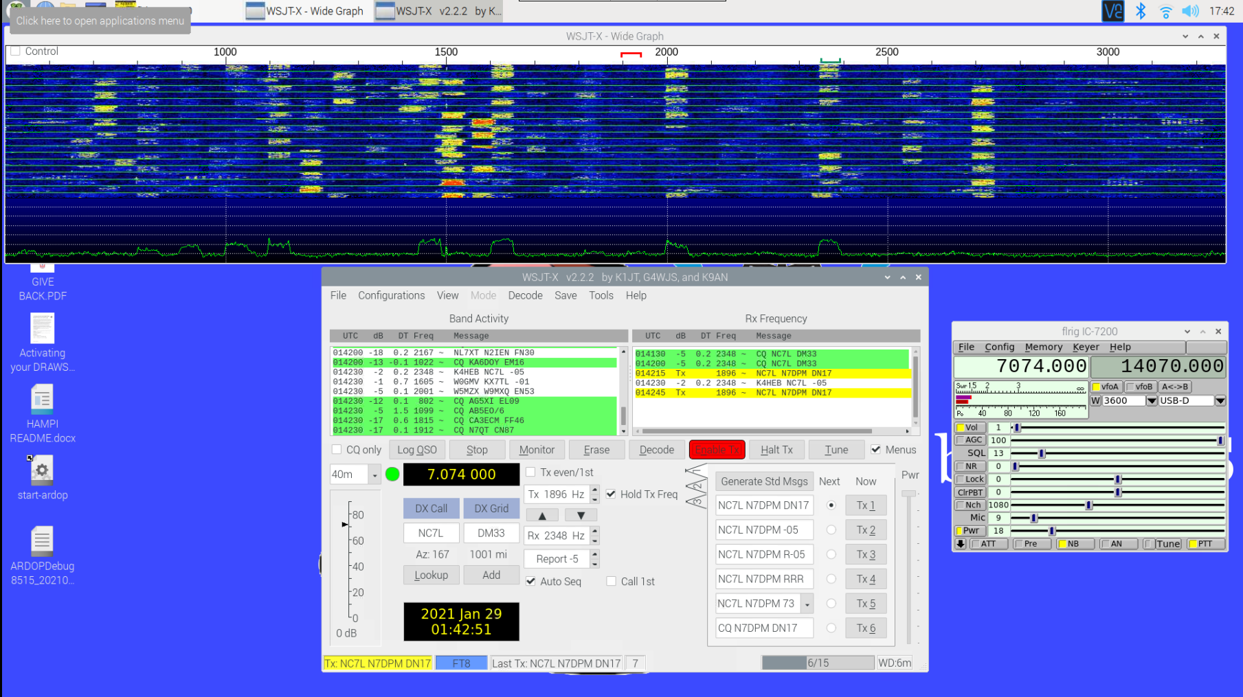
The video above shows why I call FT8 “the speed dating of ham radio.” The waterfall display at the top shows about 2,500 Hz of passband — the transceiver must be set up to allow as wide a possible band of frequencies through to WSJT-X (tip o’ the hat to Josh KI6NAZ for the help getting that right.) The FT8 algorithm decodes every 50-Hz wide FT8 signal in the passband at once; that along with the fact that each transmission is 15 seconds long followed by 15 seconds idle results in the characteristic checkerboard appearance on the waterfall display.

The characteristic FT8 checkerboard pattern develops on the WSJT-X waterfall. The 40-meter band was pretty good tonight, but I couldn’t make any QSOs.

Decoded messages are displayed in the left window of WSJT-X, with operators generally looking for stations calling CQ. Clicking on an entry in the Band Activity window starts a series of automatic messages, with WSJT-X keying up the transmitter and sending a minimal QSO — basically just the two call signs, a grid square locator, and the received signal strength. It’s important to note that the two sides of the conversation don’t have to be, and in fact shouldn’t be, on the same frequency — the other operator’s copy of WSJT-X will decode the entire passband if it can. Once the acknowledgment of the CQ is received by the other station, the exchange of messages is entirely automatic, until the final 73s are sent and WSJT-X gives both sides a chance to log the QSO.

Since I’ve set up my end-fed half-wave antenna for the HF bands and gotten WSJT-X installed, I’ve made quite a few contacts. Most of them have been in the continental US and Canada, but I did manage to bag Japan on 30 meters last week, which was a treat. The fact that I could do all of this without once picking up the microphone, struggling to think of something to say, is a godsend to me, and the fact that WSJT-X is able to decode signals that are so far down into the noise floor is an intoxicating technical feat.  It’s also really nice to sit down for a half-hour or so before dinner and bang out a couple of low-effort QSOs without having to invest too much in the process.

As mentioned, FT8 isn’t the only weak-signal mode that Joe Taylor and his collaborators built into WSJT-X. Next time on The $50 Ham, we’ll look at the equally addictive WSPR mode, and see how you can actually work HF bands for far less than $50, transmitter included.

source https://hackaday.com/2021/02/10/the-50-ham-digital-modes-with-wsjt-x/

The $50 Ham: Digital Modes with WSJT-X

As it is generally practiced, ham radio is a little like going to the grocery store and striking up a conversation with everyone you bump into as you ply the aisles. Except that the grocery store is the size of the planet, and everyone brings their own shopping cart, some of which are highly modified and really expensive. And pretty much every conversation is about said carts, or about the grocery store itself.

With that admittedly iffy analogy in mind, if you’re not the kind of person who would normally strike up a conversation with someone while shopping, you might think that you’d be a poor fit for amateur radio. But just because that’s the way that most people exercise their ham radio privileges doesn’t mean it’s the only way. Exploring a few of the more popular ways to leverage the high-frequency (HF) bands and see what can be done on a limited budget, in terms of both cost of equipment as well as the amount of power used, is the focus of this installment of The $50 Ham. Welcome to the world of microphone-optional ham radio: weak-signal digital modes.

Just a Regular Joe

First things first, let me make it clear that there are a ton of modes available to amateur radio service licensees that don’t require talking into a microphone, going right back to the beginning of radio with continuous wave (CW) modes. Banging out dits and dahs with a straight key is perhaps the original digital mode, if we stretch the meaning of the term just a wee bit from its current modern connotation of transmitting and receiving encoded messages using computers, either built into the radio or attached as a separate component. I’ll use that as my definition of “digital mode” for the purposes of this article.

But even with that stricter definition, there is still a huge ecosystem of digital modes that have cropped up over the history of ham radio;  the desire for communications without the need to be a conversationalist goes way back, it seems. But for this article, I’ll be focusing on a couple of modes within the “weak signals” family of modes, mainly because I find them fascinating and incredibly useful, and I get a real kick out of seeing what kinds of contacts are possible using less power than it takes to light up an LED light bulb.

When you get into the weak-signal space, one name keeps popping up: Joe Taylor (K1JT). Joe is a ham based in New Jersey, and when you first start hearing about him, you figure he’s just a, well, regular Joe, an old school ham who has come up with some clever software to make low-power signals easier to pull out of a high-noise environment. And while that’s certainly true, it quickly becomes apparent that Joe is a lot more than that. Joseph Hooton Taylor, Jr. earned his Ph.D. in astronomy from Harvard in 1968. He joined the physics faculty at Princeton in 1980, and has won pretty much every major prize in physics and mathematics, including the Draper Medal, the Wolf Prize, and in 1993, the Nobel Prize in Physics.

The Magic of WSJT-X

For all these lofty achievements, in many ways Joe is very much a “ham’s ham”, and since his retirement in 2006 he has turned his considerable experience in digital signal processing toward an all-encompassing weak-signals package called “WSJT“, for “weak signals, Joe Taylor.” Actually first written in 2001, the program has undergone nearly constant revision and updating by Joe and a cadre of digital-modes enthusiasts, with the latest incarnation, WSJT-X, which implements ten different weak-signal digital modes.

Joseph H. Taylor, Jr. (K1JT), 1993 Nobel Prize in Physics. Source: Nobel.org.

We’ll skip a deep dive into the DSP techniques underpinning WSJT-X — although it’s fascinating stuff and probably worthy of an article all by itself — and suffice it to say that the package implements various multiple frequency-shift keying (MFSK) modulation methods, each of which is optimized to work under different propagation conditions. The ten modes currently implemented cover everything from high-noise ionospheric propagation to tropospheric scatter, with modes that support bouncing signals off meteor ionization trails or even listening to your own signals bouncing off the Moon.

Even though WSJT-X modes are separated into broad “fast” and “slow” categories, by modern networking standards, they’re all pretty slow. Typical bit-rates range from a dozen characters per second to 400 baud or so. The low-throughput nature of these modes is entirely by design; by not attempting to achieve blazing speeds, WSJT-X makes very efficient use of the spectrum. Some modes only need a few hertz of bandwidth, with the tradeoff being that even very short messages can take multiple minutes to transmit.

The mode that I’ve been playing with most lately, FT8, is a relatively recent addition to the WSJT-X suite. FT8 was written by Joe Taylor and Steve Franke (K9AN), hence the “FT” in the moniker. The “8” refers to “8-FSK”, which means that the modulation scheme uses eight different tones spaced 6.25 Hz apart. Each FT8 signal therefore occupies 50 Hz, a huge chunk of bandwidth when compared to other weak-signal modes, but still pretty compact. All that extra bandwidth means that FT8 transmissions can be much shorter than, say, a 30-minute transmission on JT9. That makes FT8 suitable for quick QSOs and contesting, which is sort of the contact sport of amateur radio.

Speed Dating for Hams

While FT8 is fast, the tradeoff is message length. Each FT8 transmission encodes only 75 bits, with a 12-bit cyclic-redundancy check (CRC). That and the rapid turnaround time means that most operators rely on automation built into WSJT-X, as well as standardized messages, to make their FT8 contacts.

Setting up WSJT-X and getting a transceiver ready for FT8 is highly dependent on your computer and your radio. In my case, I built a dedicated Raspberry Pi 4 to run my ham radio operation, using the excellent Ham Pi image by Dave Slotter (W3DJS). I also attempted to use KM4ACK’s equally excellent Build-a-Pi image, but I had trouble getting my Icom IC-7200 transceiver talking to WSJT-X, and rather than devote a lot of time to troubleshooting I just tried the Ham Pi build. Both images have outstanding communities that will help you get spun up, as does WSJT-X, which has a forum where you’ll often see Joe Taylor pop in to answer questions. A community that has a Nobel laureate as a frequent contributor is a strong community indeed.

The video above shows why I call FT8 “the speed dating of ham radio.” The waterfall display at the top shows about 2,500 Hz of passband — the transceiver must be set up to allow as wide a possible band of frequencies through to WSJT-X (tip o’ the hat to Josh KI6NAZ for the help getting that right.) The FT8 algorithm decodes every 50-Hz wide FT8 signal in the passband at once; that along with the fact that each transmission is 15 seconds long followed by 15 seconds idle results in the characteristic checkerboard appearance on the waterfall display.

The characteristic FT8 checkerboard pattern develops on the WSJT-X waterfall. The 40-meter band was pretty good tonight, but I couldn’t make any QSOs.

Decoded messages are displayed in the left window of WSJT-X, with operators generally looking for stations calling CQ. Clicking on an entry in the Band Activity window starts a series of automatic messages, with WSJT-X keying up the transmitter and sending a minimal QSO — basically just the two call signs, a grid square locator, and the received signal strength. It’s important to note that the two sides of the conversation don’t have to be, and in fact shouldn’t be, on the same frequency — the other operator’s copy of WSJT-X will decode the entire passband if it can. Once the acknowledgment of the CQ is received by the other station, the exchange of messages is entirely automatic, until the final 73s are sent and WSJT-X gives both sides a chance to log the QSO.

Since I’ve set up my end-fed half-wave antenna for the HF bands and gotten WSJT-X installed, I’ve made quite a few contacts. Most of them have been in the continental US and Canada, but I did manage to bag Japan on 30 meters last week, which was a treat. The fact that I could do all of this without once picking up the microphone, struggling to think of something to say, is a godsend to me, and the fact that WSJT-X is able to decode signals that are so far down into the noise floor is an intoxicating technical feat.  It’s also really nice to sit down for a half-hour or so before dinner and bang out a couple of low-effort QSOs without having to invest too much in the process.

As mentioned, FT8 isn’t the only weak-signal mode that Joe Taylor and his collaborators built into WSJT-X. Next time on The $50 Ham, we’ll look at the equally addictive WSPR mode, and see how you can actually work HF bands for far less than $50, transmitter included.

source https://hackaday.com/2021/02/10/the-50-ham-digital-modes-with-wsjt-x/

The $50 Ham: Digital Modes with WSJT-X

As it is generally practiced, ham radio is a little like going to the grocery store and striking up a conversation with everyone you bump into as you ply the aisles. Except that the grocery store is the size of the planet, and everyone brings their own shopping cart, some of which are highly modified and really expensive. And pretty much every conversation is about said carts, or about the grocery store itself.

With that admittedly iffy analogy in mind, if you’re not the kind of person who would normally strike up a conversation with someone while shopping, you might think that you’d be a poor fit for amateur radio. But just because that’s the way that most people exercise their ham radio privileges doesn’t mean it’s the only way. Exploring a few of the more popular ways to leverage the high-frequency (HF) bands and see what can be done on a limited budget, in terms of both cost of equipment as well as the amount of power used, is the focus of this installment of The $50 Ham. Welcome to the world of microphone-optional ham radio: weak-signal digital modes.

Just a Regular Joe

First things first, let me make it clear that there are a ton of modes available to amateur radio service licensees that don’t require talking into a microphone, going right back to the beginning of radio with continuous wave (CW) modes. Banging out dits and dahs with a straight key is perhaps the original digital mode, if we stretch the meaning of the term just a wee bit from its current modern connotation of transmitting and receiving encoded messages using computers, either built into the radio or attached as a separate component. I’ll use that as my definition of “digital mode” for the purposes of this article.

But even with that stricter definition, there is still a huge ecosystem of digital modes that have cropped up over the history of ham radio;  the desire for communications without the need to be a conversationalist goes way back, it seems. But for this article, I’ll be focusing on a couple of modes within the “weak signals” family of modes, mainly because I find them fascinating and incredibly useful, and I get a real kick out of seeing what kinds of contacts are possible using less power than it takes to light up an LED light bulb.

When you get into the weak-signal space, one name keeps popping up: Joe Taylor (K1JT). Joe is a ham based in New Jersey, and when you first start hearing about him, you figure he’s just a, well, regular Joe, an old school ham who has come up with some clever software to make low-power signals easier to pull out of a high-noise environment. And while that’s certainly true, it quickly becomes apparent that Joe is a lot more than that. Joseph Hooton Taylor, Jr. earned his Ph.D. in astronomy from Harvard in 1968. He joined the physics faculty at Princeton in 1980, and has won pretty much every major prize in physics and mathematics, including the Draper Medal, the Wolf Prize, and in 1993, the Nobel Prize in Physics.

The Magic of WSJT-X

For all these lofty achievements, in many ways Joe is very much a “ham’s ham”, and since his retirement in 2006 he has turned his considerable experience in digital signal processing toward an all-encompassing weak-signals package called “WSJT“, for “weak signals, Joe Taylor.” Actually first written in 2001, the program has undergone nearly constant revision and updating by Joe and a cadre of digital-modes enthusiasts, with the latest incarnation, WSJT-X, which implements ten different weak-signal digital modes.

Joseph H. Taylor, Jr. (K1JT), 1993 Nobel Prize in Physics. Source: Nobel.org.

We’ll skip a deep dive into the DSP techniques underpinning WSJT-X — although it’s fascinating stuff and probably worthy of an article all by itself — and suffice it to say that the package implements various multiple frequency-shift keying (MFSK) modulation methods, each of which is optimized to work under different propagation conditions. The ten modes currently implemented cover everything from high-noise ionospheric propagation to tropospheric scatter, with modes that support bouncing signals off meteor ionization trails or even listening to your own signals bouncing off the Moon.

Even though WSJT-X modes are separated into broad “fast” and “slow” categories, by modern networking standards, they’re all pretty slow. Typical bit-rates range from a dozen characters per second to 400 baud or so. The low-throughput nature of these modes is entirely by design; by not attempting to achieve blazing speeds, WSJT-X makes very efficient use of the spectrum. Some modes only need a few hertz of bandwidth, with the tradeoff being that even very short messages can take multiple minutes to transmit.

The mode that I’ve been playing with most lately, FT8, is a relatively recent addition to the WSJT-X suite. FT8 was written by Joe Taylor and Steve Franke (K9AN), hence the “FT” in the moniker. The “8” refers to “8-FSK”, which means that the modulation scheme uses eight different tones spaced 6.25 Hz apart. Each FT8 signal therefore occupies 50 Hz, a huge chunk of bandwidth when compared to other weak-signal modes, but still pretty compact. All that extra bandwidth means that FT8 transmissions can be much shorter than, say, a 30-minute transmission on JT9. That makes FT8 suitable for quick QSOs and contesting, which is sort of the contact sport of amateur radio.

Speed Dating for Hams

While FT8 is fast, the tradeoff is message length. Each FT8 transmission encodes only 75 bits, with a 12-bit cyclic-redundancy check (CRC). That and the rapid turnaround time means that most operators rely on automation built into WSJT-X, as well as standardized messages, to make their FT8 contacts.

Setting up WSJT-X and getting a transceiver ready for FT8 is highly dependent on your computer and your radio. In my case, I built a dedicated Raspberry Pi 4 to run my ham radio operation, using the excellent Ham Pi image by Dave Slotter (W3DJS). I also attempted to use KM4ACK’s equally excellent Build-a-Pi image, but I had trouble getting my Icom IC-7200 transceiver talking to WSJT-X, and rather than devote a lot of time to troubleshooting I just tried the Ham Pi build. Both images have outstanding communities that will help you get spun up, as does WSJT-X, which has a forum where you’ll often see Joe Taylor pop in to answer questions. A community that has a Nobel laureate as a frequent contributor is a strong community indeed.

The video above shows why I call FT8 “the speed dating of ham radio.” The waterfall display at the top shows about 2,500 Hz of passband — the transceiver must be set up to allow as wide a possible band of frequencies through to WSJT-X (tip o’ the hat to Josh KI6NAZ for the help getting that right.) The FT8 algorithm decodes every 50-Hz wide FT8 signal in the passband at once; that along with the fact that each transmission is 15 seconds long followed by 15 seconds idle results in the characteristic checkerboard appearance on the waterfall display.

The characteristic FT8 checkerboard pattern develops on the WSJT-X waterfall. The 40-meter band was pretty good tonight, but I couldn’t make any QSOs.

Decoded messages are displayed in the left window of WSJT-X, with operators generally looking for stations calling CQ. Clicking on an entry in the Band Activity window starts a series of automatic messages, with WSJT-X keying up the transmitter and sending a minimal QSO — basically just the two call signs, a grid square locator, and the received signal strength. It’s important to note that the two sides of the conversation don’t have to be, and in fact shouldn’t be, on the same frequency — the other operator’s copy of WSJT-X will decode the entire passband if it can. Once the acknowledgment of the CQ is received by the other station, the exchange of messages is entirely automatic, until the final 73s are sent and WSJT-X gives both sides a chance to log the QSO.

Since I’ve set up my end-fed half-wave antenna for the HF bands and gotten WSJT-X installed, I’ve made quite a few contacts. Most of them have been in the continental US and Canada, but I did manage to bag Japan on 30 meters last week, which was a treat. The fact that I could do all of this without once picking up the microphone, struggling to think of something to say, is a godsend to me, and the fact that WSJT-X is able to decode signals that are so far down into the noise floor is an intoxicating technical feat.  It’s also really nice to sit down for a half-hour or so before dinner and bang out a couple of low-effort QSOs without having to invest too much in the process.

As mentioned, FT8 isn’t the only weak-signal mode that Joe Taylor and his collaborators built into WSJT-X. Next time on The $50 Ham, we’ll look at the equally addictive WSPR mode, and see how you can actually work HF bands for far less than $50, transmitter included.

source https://hackaday.com/2021/02/10/the-50-ham-digital-modes-with-wsjt-x/