[Attoparsec] has been building intriguing musical projects on his YouTube channel for a while and his latest is no exception. Dubbed simply as “Node Module”, it is a rack-mounted hardware-based Markov chain beat sequencer. Traditionally Markov chains are software state machines that transition between states with given probabilities, often learned from a training corpus. That same principle has been applied to hardware beat sequencing.
Each Node Module has a trigger input, four outputs each with a potentiometer, and a trigger out. [Attoparsec] has a wonderful explanation of all the different parts and theories that make up the module at the start of his video, but the basic operation is that a trigger input comes in and the potentiometers are read to determine the probabilities of each output. One is randomly selected and fired. As you can imagine, there are loops and even dead-end nodes and for some musical pieces there is a certain number of beats expected, so a clever reset signal can be sent to pull the chain back to the initial starting state at a regular interval. The results are interesting to listen to and even better to imagine all the possibilities.
System76, a computer manufacturer known for selling machines which run Linux, recently unveiled the complete sources for their forthcoming Launch mechanical keyboard. Made with familiar tools, mass produced, and backed by a stable company it looks like the Launch will be a compelling entrant into the world of mechanical keyboards.
Back in March of 2020 System76 published a blog post about a new project they were embarking on; a mechanical keyboard with an unusual layout. At the time there was scant information available besides a summer 2021 target and little was heard until last week when they opened up access to the Launch repository. Everything should be recognizable if you’ve ever looked at the sources for a customized mechanical keyboard before, which is what gets our attention. Electrical sources are authored with KiCad and should be easy to tweak or fabricate. And mechanical components are provided in STEP files with mechanical drawings, presumably because they intend to actually manufacture these.
Feature wise all the usual hallmarks of a well designed keyboard are here. The Launch uses hostswap sockets to make it easy to install the usual Cherry MX compatible switch options, and includes per-key RGB backlighting courtesy of SK6805 LEDs. The ATmega32U4 runs the popular and extremely capable QMK firmware instead of something bespoke, so it should be easy to customize to the user’s desire.
System76 touts an unusual key layout, but if you’ve seen a 75% keyboard before it shouldn’t be too threatening (though we do wonder about that shrunken right shift). The most unusual feature is that it features a USB hub capable of full speed 10 gigabit USB 3.1 Gen 2 on two USB-C and two USB-A ports. It’s worth checking out the schematic to appreciate how much more complicated the hub design is than the rest of the keyboard, which is practically vestigial in comparison.
The remaining unknown is how the Launch integrates with Pop!_OS, System76’s awkwardly named remix of Ubuntu. They promise deep, compelling integration and we’re excited to see how that manifests.
System76, a computer manufacturer known for selling machines which run Linux, recently unveiled the complete sources for their forthcoming Launch mechanical keyboard. Made with familiar tools, mass produced, and backed by a stable company it looks like the Launch will be a compelling entrant into the world of mechanical keyboards.
Back in March of 2020 System76 published a blog post about a new project they were embarking on; a mechanical keyboard with an unusual layout. At the time there was scant information available besides a summer 2021 target and little was heard until last week when they opened up access to the Launch repository. Everything should be recognizable if you’ve ever looked at the sources for a customized mechanical keyboard before, which is what gets our attention. Electrical sources are authored with KiCad and should be easy to tweak or fabricate. And mechanical components are provided in STEP files with mechanical drawings, presumably because they intend to actually manufacture these.
Feature wise all the usual hallmarks of a well designed keyboard are here. The Launch uses hostswap sockets to make it easy to install the usual Cherry MX compatible switch options, and includes per-key RGB backlighting courtesy of SK6805 LEDs. The ATmega32U4 runs the popular and extremely capable QMK firmware instead of something bespoke, so it should be easy to customize to the user’s desire.
System76 touts an unusual key layout, but if you’ve seen a 75% keyboard before it shouldn’t be too threatening (though we do wonder about that shrunken right shift). The most unusual feature is that it features a USB hub capable of full speed 10 gigabit USB 3.1 Gen 2 on two USB-C and two USB-A ports. It’s worth checking out the schematic to appreciate how much more complicated the hub design is than the rest of the keyboard, which is practically vestigial in comparison.
The remaining unknown is how the Launch integrates with Pop!_OS, System76’s awkwardly named remix of Ubuntu. They promise deep, compelling integration and we’re excited to see how that manifests.
System76, a computer manufacturer known for selling machines which run Linux, recently unveiled the complete sources for their forthcoming Launch mechanical keyboard. Made with familiar tools, mass produced, and backed by a stable company it looks like the Launch will be a compelling entrant into the world of mechanical keyboards.
Back in March of 2020 System76 published a blog post about a new project they were embarking on; a mechanical keyboard with an unusual layout. At the time there was scant information available besides a summer 2021 target and little was heard until last week when they opened up access to the Launch repository. Everything should be recognizable if you’ve ever looked at the sources for a customized mechanical keyboard before, which is what gets our attention. Electrical sources are authored with KiCad and should be easy to tweak or fabricate. And mechanical components are provided in STEP files with mechanical drawings, presumably because they intend to actually manufacture these.
Feature wise all the usual hallmarks of a well designed keyboard are here. The Launch uses hostswap sockets to make it easy to install the usual Cherry MX compatible switch options, and includes per-key RGB backlighting courtesy of SK6805 LEDs. The ATmega32U4 runs the popular and extremely capable QMK firmware instead of something bespoke, so it should be easy to customize to the user’s desire.
System76 touts an unusual key layout, but if you’ve seen a 75% keyboard before it shouldn’t be too threatening (though we do wonder about that shrunken right shift). The most unusual feature is that it features a USB hub capable of full speed 10 gigabit USB 3.1 Gen 2 on two USB-C and two USB-A ports. It’s worth checking out the schematic to appreciate how much more complicated the hub design is than the rest of the keyboard, which is practically vestigial in comparison.
The remaining unknown is how the Launch integrates with Pop!_OS, System76’s awkwardly named remix of Ubuntu. They promise deep, compelling integration and we’re excited to see how that manifests.
Floppy disks are rapidly aging, and archivists are working hard to preserve what data is left. This has led to the development of advanced floppy controllers capable of capturing the raw flux data from disks. [bzotto] was experimenting with the Applesauce archival hardware, and had some fun with the tools.
The result is a highly esoteric Easter egg. [bzotto]’s Picturedsk tool takes a bitmap image as input, and imprints that image into the magnetic flux of the disk. Thus, when viewing a dump of the disk’s magnetic flux on an archival program, the hidden image will be revealed. As an extra treat, it also writes a 1-bit version of the image to track 0, along with a barebones Apple ][ program to display the image and implore the user to investigate further.
It’s a fun hack that we could imagine being used as part of a game at a retro computing con, when we get to go back to those of course. We’ve seen Applesauce used before, too. If you’ve got your own archival projects on the go, be sure to let us know!
Floppy disks are rapidly aging, and archivists are working hard to preserve what data is left. This has led to the development of advanced floppy controllers capable of capturing the raw flux data from disks. [bzotto] was experimenting with the Applesauce archival hardware, and had some fun with the tools.
The result is a highly esoteric Easter egg. [bzotto]’s Picturedsk tool takes a bitmap image as input, and imprints that image into the magnetic flux of the disk. Thus, when viewing a dump of the disk’s magnetic flux on an archival program, the hidden image will be revealed. As an extra treat, it also writes a 1-bit version of the image to track 0, along with a barebones Apple ][ program to display the image and implore the user to investigate further.
It’s a fun hack that we could imagine being used as part of a game at a retro computing con, when we get to go back to those of course. We’ve seen Applesauce used before, too. If you’ve got your own archival projects on the go, be sure to let us know!
Building antennas is a time-honored ham radio tradition. Shortwave antennas tend to be bulky but at VHF frequencies the antenna sizes are pretty manageable. [Fjkaan’s] 2 meter quadrifilar helicoidal antenna is a good example and the structure for it can be created with 3D printing combined with electrical conduit.
Many people, including [G4ILO] use PVC pipe for the structure, and that design inspired [Fjkaan]. Despite being a bit less substantial, the conduit seems to work well and it is easy to cut. The helical design is common for satellite work owing to its circular polarization and omnidirectional pattern.
A quadrifilar helicoidal antenna is really two antennas in one, with a phase difference of 90 degrees between the two. There are several ways this can be accomplished, but in practice, most of these antennas use different loop sizes for the two antennas. One loop will be a bit larger than the frequency of interest, and thus will be inductive. The other loop will be a little smaller, and therefore will exhibit capacitive reactance at the center frequency.
Even though the antennas are both reactive, in parallel, the reactances cancel leaving a nice resistive load to match the radio. The feed at the top, however, needs to balance through some form of balun or choke.
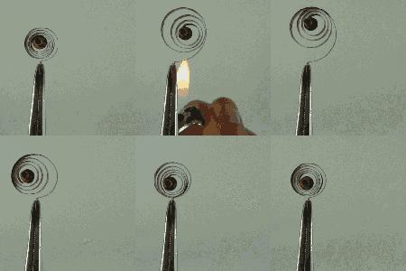
Measuring temperature turns out to be a fundamental function for a huge number of devices. You furnace’s programmable thermostat and digital clocks are obvious examples. If you just needed to know if a certain temperature is exceeded, you could use a bimetalic coil and a microswitch (or a mercury switch as was the method with old thermostats). But these days we want precision over a range of readings, so there are thermocouples that generate a small voltage, RTDs that change resistance with temperature, thermistors that also change resistance with temperature, infrared sensors, and vibrating wire sensors. The bandgap voltage of a semiconductor junction varies with temperature and that’s predictable and measurable, too. There are probably other methods too, some of which are probably pretty creative.
You can often think of creative ways to do any measurement. There’s an old joke about the smart-alec student in physics class. The question was how do you find the height of a building using a barometer. One answer was to drop the barometer from the top of the building and time how long it takes to hit the ground. Another answer — doubtlessly an engineering student — wanted to find the building engineer and offer to give them the barometer in exchange for the height of the building. By the same token, you could find the temperature by monitoring a standard thermometer with a camera or even a level sensor which is a topic for another post.
The point is, there are plenty of ways to measure anything, but in every case, you are converting what you want to know (temperature) into something you know how to measure like voltage, current, or physical position. Let’s take a look at how some of the most interesting temperature sensors accomplish this.
Thermocouples
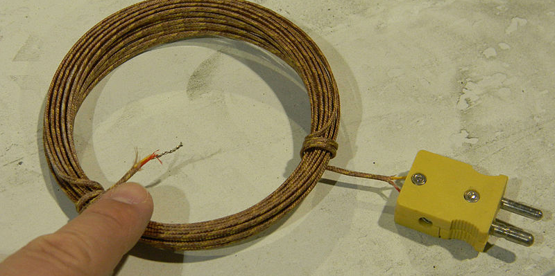
Thermocouples take advantage of something called the Seebeck effect. When two dissimilar metals form a junction and experience a temperature gradient, an electric potential forms. The key is that it is a gradient in temperature that makes the device work. Thermocouples have a hot junction and a cold junction. If you want to measure temperature, you need a reference junction. As an aside, the effect works in reverse — the Peltier effect — where passing current through a pair of junctions makes one side hot and the other one cold.
In the old days, you’d plunge the cold junction into a bucket of ice. Today, it is more likely that you’ll use another method to get the temperature of the cold junction and then compensate. There are chips that will do that for you, of course.
Why not just use the other method to start with? Thermocouples have several advantages. For one thing, you can measure up to a few thousand degrees with one. Since they are just two pieces of wire, they are robust and reliable. In hot or harsh environments, they are easy to manage and, usually, at the cold end you have a little nicer environment.
The downside is that the temperature reading is not linear. You’ll see different types of thermocouples and each type uses two different wire materials. The type tells you what calibration curve to use and, of course, you select the metal for the application you need. For example, a type J uses iron as one of the two wires and a type T uses copper.
The only other big consideration is how you run wires to the thermocouple. Since the device operates on a junction between two different types of wires, you have to be careful how you connect other wires to the device. Want to know more? [Bil Herd] did a deep dive into how to build a thermocouple amplifier.
Thermocouples that measure infrared from a distance are known as thermopiles. These are common in non-contact thermometers and passive IR (PIR) sensors. A PIR sensor detects the difference in temperature between two sensors and infers that something has changed in the field of view.
Resistance Devices
There are several different types of material that can exhibit temperature changes with resistance. The biggest factor is if the device has a positive or negative temperature coefficient. In other words, does the resistance go up or down in response to a change in temperature?
Most of these devices are also non-linear, but they are also inexpensive and easy to use. You can measure the resistance using any method you like. A common technique is to use the resistor as part of a voltage divider or bridge and measure the output voltage. However, if you’d rather not tie up an analog input, you can connect the resistor to a capacitor and measure the time it takes to charge.
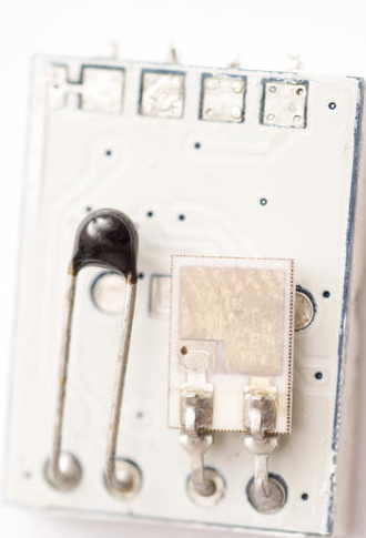
Thermistors are slightly different in construction from resistance temperature detectors, or RTDs. Usually, thermistors have less hysteresis and self-heating problems than the metal-based (often platinum) RTDs. However, in either case, you’ll have to measure resistance and fit it to a curve to get the real temperature.
Reading thermistors is a very common operation and there are a lot of tricks people have developed over the years. You can also spend math processing to get better curve fits, or do simple math and get less accuracy.
Semiconductor Junctions and Accidental Sensors
The bandgap voltage of semiconductor material varies predictably with temperature. If you ever get deep into solid state design, you’ll see the T term in the diode equation and all its manifestations. It is no surprise, then, that a lot of ICs use this property for sensing temperature.
Some chips are made to be temperature sensors. For example, the common LM34 and LM35 chips exploit this property with some additional circuits to provide a nice 10mV per degree (the LM34 measures Farhenheit and the LM35 measures Celcius). That makes them very easy to use.
Some chips, like the CPU in your PC, use the same method to measure internal temperature for reporting and thermal management. However, there are other ways non-temperature sensor ICs can measure temperature.
It turns out, almost all of our circuits are sensitive to temperature in some way. Measuring the internal clock of a CPU against an external reference can show temperature-induced changes.
Oddball Sensors
There are a multitude of other ways to measure temperature. For example, a vibrating wire sensor uses what amounts to a guitar string. The measurement involves exciting the string and detecting the frequency of vibration. As the supporting structure shrinks and expands with temperature changes, the tone of the string changes.
You can get an approximate temperature in degrees Fahrenheit by counting the number of chirps crickets make. Count the number of chirps in 15 seconds and then add 37. It wouldn’t surprise me if someone’s done that in some obscure instrument. [Kevin] in Terre Haute says the number is 40 in the video below, and not 37, but I guess it isn’t an exact science.
Of course, an increasingly common way to measure temperature is to use some form of smart sensor. A module or IC can use any of the methods we’ve talked about, convert it to engineering units, and send the data over something like an I2C bus. This is a level abstraction, but you still ought to understand the underlying benefits and limitations involved with the sensor you want to use.
While there may be more, there aren’t any other common techniques for measuring temperature. But there are still lots of sensors left to talk about in future articles.
Measuring temperature turns out to be a fundamental function for a huge number of devices. You furnace’s programmable thermostat and digital clocks are obvious examples. If you just needed to know if a certain temperature is exceeded, you could use a bimetalic coil and a microswitch (or a mercury switch as was the method with old thermostats). But these days we want precision over a range of readings, so there are thermocouples that generate a small voltage, RTDs that change resistance with temperature, thermistors that also change resistance with temperature, infrared sensors, and vibrating wire sensors. The bandgap voltage of a semiconductor junction varies with temperature and that’s predictable and measurable, too. There are probably other methods too, some of which are probably pretty creative.
You can often think of creative ways to do any measurement. There’s an old joke about the smart-alec student in physics class. The question was how do you find the height of a building using a barometer. One answer was to drop the barometer from the top of the building and time how long it takes to hit the ground. Another answer — doubtlessly an engineering student — wanted to find the building engineer and offer to give them the barometer in exchange for the height of the building. By the same token, you could find the temperature by monitoring a standard thermometer with a camera or even a level sensor which is a topic for another post.
The point is, there are plenty of ways to measure anything, but in every case, you are converting what you want to know (temperature) into something you know how to measure like voltage, current, or physical position. Let’s take a look at how some of the most interesting temperature sensors accomplish this.
Thermocouples
Thermocouples take advantage of something called the Seebeck effect. When two dissimilar metals form a junction and experience a temperature gradient, an electric potential forms. The key is that it is a gradient in temperature that makes the device work. Thermocouples have a hot junction and a cold junction. If you want to measure temperature, you need a reference junction. As an aside, the effect works in reverse — the Peltier effect — where passing current through a pair of junctions makes one side hot and the other one cold.
In the old days, you’d plunge the cold junction into a bucket of ice. Today, it is more likely that you’ll use another method to get the temperature of the cold junction and then compensate. There are chips that will do that for you, of course.
Why not just use the other method to start with? Thermocouples have several advantages. For one thing, you can measure up to a few thousand degrees with one. Since they are just two pieces of wire, they are robust and reliable. In hot or harsh environments, they are easy to manage and, usually, at the cold end you have a little nicer environment.
The downside is that the temperature reading is not linear. You’ll see different types of thermocouples and each type uses two different wire materials. The type tells you what calibration curve to use and, of course, you select the metal for the application you need. For example, a type J uses iron as one of the two wires and a type T uses copper.
The only other big consideration is how you run wires to the thermocouple. Since the device operates on a junction between two different types of wires, you have to be careful how you connect other wires to the device. Want to know more? [Bil Herd] did a deep dive into how to build a thermocouple amplifier.
Thermocouples that measure infrared from a distance are known as thermopiles. These are common in non-contact thermometers and passive IR (PIR) sensors. A PIR sensor detects the difference in temperature between two sensors and infers that something has changed in the field of view.
Resistance Devices
There are several different types of material that can exhibit temperature changes with resistance. The biggest factor is if the device has a positive or negative temperature coefficient. In other words, does the resistance go up or down in response to a change in temperature?
Most of these devices are also non-linear, but they are also inexpensive and easy to use. You can measure the resistance using any method you like. A common technique is to use the resistor as part of a voltage divider or bridge and measure the output voltage. However, if you’d rather not tie up an analog input, you can connect the resistor to a capacitor and measure the time it takes to charge.
Thermistors are slightly different in construction from resistance temperature detectors, or RTDs. Usually, thermistors have less hysteresis and self-heating problems than the metal-based (often platinum) RTDs. However, in either case, you’ll have to measure resistance and fit it to a curve to get the real temperature.
Reading thermistors is a very common operation and there are a lot of tricks people have developed over the years. You can also spend math processing to get better curve fits, or do simple math and get less accuracy.
Semiconductor Junctions and Accidental Sensors
The bandgap voltage of semiconductor material varies predictably with temperature. If you ever get deep into solid state design, you’ll see the T term in the diode equation and all its manifestations. It is no surprise, then, that a lot of ICs use this property for sensing temperature.
Some chips are made to be temperature sensors. For example, the common LM34 and LM35 chips exploit this property with some additional circuits to provide a nice 10mV per degree (the LM34 measures Farhenheit and the LM35 measures Celcius). That makes them very easy to use.
Some chips, like the CPU in your PC, use the same method to measure internal temperature for reporting and thermal management. However, there are other ways non-temperature sensor ICs can measure temperature.
It turns out, almost all of our circuits are sensitive to temperature in some way. Measuring the internal clock of a CPU against an external reference can show temperature-induced changes.
Oddball Sensors
There are a multitude of other ways to measure temperature. For example, a vibrating wire sensor uses what amounts to a guitar string. The measurement involves exciting the string and detecting the frequency of vibration. As the supporting structure shrinks and expands with temperature changes, the tone of the string changes.
You can get an approximate temperature in degrees Fahrenheit by counting the number of chirps crickets make. Count the number of chirps in 15 seconds and then add 37. It wouldn’t surprise me if someone’s done that in some obscure instrument. [Kevin] in Terre Haute says the number is 40 in the video below, and not 37, but I guess it isn’t an exact science.
Of course, an increasingly common way to measure temperature is to use some form of smart sensor. A module or IC can use any of the methods we’ve talked about, convert it to engineering units, and send the data over something like an I2C bus. This is a level abstraction, but you still ought to understand the underlying benefits and limitations involved with the sensor you want to use.
While there may be more, there aren’t any other common techniques for measuring temperature. But there are still lots of sensors left to talk about in future articles.
Hackaday editors Elliot Williams and Mike Szczys recount the coolest hacks from the past week. Most clocks keep time with a quartz crystal, but we discuss one that uses a tuning fork… like the kind you use to tune a piano. Ghidra is a powerful reverse engineering tool developed by the NSA that was recently put to good use changing an embedded thermometer display from Celsius to Fahrenheit. We talk turkey on the Texas power grid problems and Tesla’s eMMC failures. And of course there’s some room for nostalgia as we walk down memory lane with the BASIC programming language.
Take a look at the links below if you want to follow along, and as always, tell us what you think about this episode in the comments!
They say experience is the best teacher, and experience tells us they are right. When [Thomas Thiel] couldn’t find any resources about re-creating the groovy ‘caps of thocky old keebs like the Space Cadet and the C64 (or find any to buy), it was time for a little keycap experimentation.
These babies are printed in black resin and the inlay is made with white air-dry clay. After printing, they are sprayed with acrylic, and then [Thomas] works a generous amount of clay into the grooves and seals the whole thing with clear spray. [Thomas] soon figured out that the grooves had to be pretty deep for this to work right — at least 1 mm. And he had better luck thick fonts like Arial Black instead of thin fonts.
Of course, as [Thomas] mentions, you’re not restricted to white or even air-dry clay. You could go nuts with colored clay and make a retro-RGB clackable rainbow.
Let’s talk TCP. Specifically, how do the different TCP connections stay distinct, and how is a third party kept from interrupting a connection? One of the mechanisms that help accomplish this feat is the TCP sequence number. Each of the two endpoints of a TCP connection tracks an incrementing 32-bit number, corresponding to the bytes sent in the connection. It’s handy, because each side can use that value to track what parts of the data stream they have received. On missing packets, a message can be sent requesting bytes 7-15 to be resent, for instance.
Each side of the connection sets their own Initial Sequence Number (ISN), and it’s important that this number is unique, as collisions can cause stream confusion. That statement should make your security spidey sense tingle. If a collision can cause problems when it happens by chance, what can a hacker do with it intentionally? Potentially quite a bit. Knowing the current sequence number, as well as a couple other pieces of information, a third party can close a TCP stream or even inject data. The attack has been around for years, originally known as the Mitnick Attack. It was originally possible because TCP implementations used a simple counter to set the ISN. Once the security ramifications of this approach were understood, the major implementations moved to a random number generation for their ISNs.
Now to this week’s story: researchers at Forescout took the time to check 11 TCP/IP stacks for vulnerability to the old Mitnick Attack (PDF Whitepaper). Of the eleven embedded stacks texted, nine have serious weaknesses in their ISN generation. Most of the vulnerable implementations use a system time value as their ISN, while several use a predictable pseudorandom algorithm that can be easily reversed.
CVEs have been assigned, and vendors notified of “NUMBER:JACK”, Forescout’s name for the research. Most of the vulnerable software already has patches available. The problem with embedded systems is that they often never get security updates. The vulnerable network stacks are in devices like IP cameras, printers, and other “invisible” software. Time will tell if this attack shows up as part of a future IoT botnet.
Microsoft Patch Tuesday
Last week, Microsoft released their monthly round-up of patches, and there are a few interesting bugs. CVE-2021-24074 is a potential RCE resulting from improper handling of source routing packets. “Source routing” is one of the mostly forgotten IP options, though it does see some use in niche applications. Packets using this option are generally blocked by routers and security devices, making it essentially impossible to send such packets over the public internet. Windows clients also block these packets, but generate an ICMP response when such a packet is blocked. Reading between the lines, it seems that the vulnerability is triggered by the process of building the ICMP response. (Not a new problem) The patch is available, as is a simple workaround: simply dropping the incoming packets without a response.
Two other CVEs are potentially notable, though there is even less information available about them. CVE-2021-24078 is a wormable vulnerability in the Windows DNS server. Thankfully a server is only vulnerable if the DNS component has been turned on. The other is CVE-2021-26701, a rather vague “.NET Core Remote Code Execution Vulnerability”. It has a severity rating of critical, and Microsoft has indicated that the details are known in the wild.
Clubhouse Security Growing Pains
You may have heard that Clubhouse is the new social media flash-in-the-pan. Or, maybe it will stick around, who knows. If you haven’t looked into it, Clubhouse is something of an audio chatroom, where a celebrity or teacher can have a conversation with an audience. It’s still prelaunch, and there are already eight million downloads. As you might imagine, this success has put Clubhouse on the radar of security researchers, like the folks at Zerforschung. It seems that Clubhouse is built on the Agora.io platform, and the attack here is to talk directly to Agora.io rather than go through the Clubhouse app. The results? The attacker can leave the room, but maintain the connection to the backend. The username disappears, but still receives audio, and can even speak into the room. This breaks the ability to put a room into single-speaker mode and makes ejecting a user impossible.
Telegram Self-Destruct Messages
The problem? They aren’t actually destructed. [Dhiraj Mishra] did his research on the MacOS version of Telegram, and discovered that audio and video files sent in a self-destruct message is still available on the computer hard drive, even after the message timer has expired. For extra pwnage, this version of Telegram also stores the passcode in plaintext in some cases. Both issues have been fixed, so make sure you update if you use Telegram on MacOS.
More NPM Dependency Confusion
Last week we covered [Alex Birsan]’s dependency confusion attack, where a package can be uploaded to NPM that uses the name of a private package. If a company has their build system misconfigured, the public package can be pulled into the final build instead of the intended private package. Since [Alex] publicly announced the attack, nearly 300 such packages have been uploaded to NPM taking advantage of this technique. Note these are the packages that have been discovered, there are almost certainly more packages that are out there, but are yet to be discovered. [Alex] pointed out that some of these are likely other researchers aiming for bug bounties, but there might even be some legitimately malicious packages in the mix.
We’ll do our best to keep you up to date on these stories, and the rest that pop up each week, so stay tuned!
The great divide in terms of single board computers lies between those that can run some form of Linux-based distribution, and those that can not. For example the Raspberry Pi Zero is a Linux board, while the Raspberry Pi Pico’s RP2040 processor lacks the required hardware to run everybody’s favourite UNIX-like operating system. That’s not to say the new board from Cambridge can’t run any UNIX-like operating system though, as [David Given] shows us with his FUSIX port.
FUSIX is a UNIX-like operating system for less capable processors, more in the spirit of those original UNIXes than of a modern Linux-based distribution. It’s the work of the respected former Linux kernel developer and maintainer [Alan Cox], and consists of a kernel, a C compiler, and a set of core UNIX-like applications.
The RP2040 port maybe needs a little more work to be considered stable. For now, the multitasking support isn’t quite there and NAND flash support is broken, but it does have SD card support for a proper UNIX filesystem and the full set of core tools. Perhaps most interestingly, it only occupies a single core of the dual-core chip, leaving the possibility of the other core and those PIOs to be used for other purposes.
FUSIX has made the occasional appearance here over the years, but perhaps not as often as it should. If you’d like to learn a little more about the genesis of UNIX, we took a look in 2019.
Smart switches are fun, letting you control lights and appliances in your home over the web or even by voice if you’re so inclined. However, they can make day-to-day living more frustrating if they’re not set up properly with regards to your existing light switches. Thankfully, with some simple wiring, it’s possible to make everything play nice.
The method is demonstrated here by [MyHomeThings], in which an ESP8266 is used with a relay to create a basic smart switch. However, it’s wired up with a regular light switch in a typical “traveller” multiway switching scheme – just like when you have two traditional light switches controlling the same light at home. To make this work with the ESP8266, though, the microcontroller needs to be able to know the current state of the light. This is done by using a 240V to 3.3V power supply wired up in parallel with the light. When the light is on, the 3.3V supply is on. This supply feeds into a GPIO pin on the ESP8266, letting it know the light’s current state, and allowing it to set its output relay to the correct position as necessary.
A lot of us have nostalgia for our childhood toys, and as long as they’re not something like lawn darts that nostalgia often leads to fun upgrades since some of us are adults with industrial-sized air compressors. Classics like Super Soakers and Nerf guns are especially popular targets for improvements, and this Nerf machine gun from [Emiel] is no exception.
The build takes a Nerf ball-firing toy weapon and basically tosses it all out of the window in favor of a custom Nerf ball launching rifle. He starts with the lower receiver and machines a pneumatic mechanism that both loads a ball into the chamber and then launches it. This allows the rifle to be used in both single-shot mode and also in fully-automatic mode. From there, a barrel is fashioned along with the stock and other finishing touches.
[Emiel] also uses a high-speed camera to determine the speed of his new Nerf gun but unfortunately it isn’t high-speed enough, suffering from the same fate as one of the fastest man-made objects ever made, and he only has a lower bound on the speed at 400 km/h. If you don’t want to go fast with your Nerf builds, though, perhaps you should build something enormous instead.
E-ink displays haven’t revolutionized the world so much as served us humbly in e-book readers such as the Kindle and its ilk. Most such readers are designed for extended sessions reading novels and the like, but [Roni Bandini] decided a haiku-sized device was in order.
The diminutive device runs off an ESP32, which has plenty of clock cycles for easily driving displays. It’s paired with a 2.9 inch Waveshare e-ink display, upon which it delivers poetry in the popular Japanese haiku format – 5 syllables, 7 syllables, 5 syllables. Writing to the display is easy with the GxEPD library, which is compatible with a variety of common e-ink displays. Presently the poetry is hardcoded in the program, and there’s plenty that could be included with the ESP32’s roomy program storage. However, [Roni] notes it would be simple to have the reader pull poems from an SD card instead.
It’s a fun project, and a great way to get familiar with the basics of working with e-ink displays. We’d love to see a WiFi-enabled version that pulls down the hottest daily haikus fresh from the web, too. Funnily enough, our own archives only feature one other reference to the famous Japanese art, which has little to do with poetry. If you fancy changing that, make something relevant and drop us a line. Video after the break.
There are few hard and fast rules in the world of custom cyberdecks, but many of these bespoke machines do share a certain level of commonality. They generally use a low-power ARM board such as the Raspberry Pi that doesn’t consume much power or require any exotic thermal management, and a large mechanical keyboard is almost a given. But at a glance, it’s clear that [Daan Gerits] wasn’t concerned with the status quo when designing the Sypherdeck.
Now to be fair, dropping the ARM single-board computer for x86 isn’t completely unheard of. But those builds tend to be considerably bulkier than the Sypherdeck. The secret here seems to be that the 3D printed enclosure doesn’t hold much else than the LattePanda and a seven inch LCD touch screen. The hatch on the side covers the rear of the power, USB, and HDMI bulkhead connectors, but it looks like there’s enough room in there to squeeze in a bit of custom electronics should you wish. There’s no obvious place to install any batteries, so if you wanted to take the show on the road, you’ll need to use an external pack.
The bigger surprise is the complete lack of an integrated keyboard. Obviously this allowed [Daan] to create an even more svelte enclosure, but of course at the cost of having to carry around an external keyboard. That said, if you’ve got some kind of use case that is completely fulfilled by the touch screen, that could be seen as an advantage. It sounds like the original plan was to make the keyboard clip onto the bottom or top of the deck, but that feature didn’t make the cut for this first version.
We live in the information age where access to the internet is considered a fundamental human right. Exercising this right does largely rely on the technological advances made in optical communication. Using light to send information has a long history: from ancient Greece, through Claude Chappe’s semaphore towers and Alexander Graham Bell’s photophone, to fiber optical networks and future satellite internet constellations currently developed by tech giants.
Let’s dive a little bit deeper into the technologies that were used to spread information with the help of light throughout history.
Semaphores and Heliographs
Reconstruction of a hydraulic telegraph at Thessaloniki Technology Museum. Credit: Gts-tg, CC BY-SA 4.0
Since light can travel in air much further than sound, visual communication has always been the method of choice to broadcast information over long distances. One of the earliest examples is the Phryctoriae from ancient Greece, a system of towers build on mountaintops that could send messages by lighting torches. Allegedly, this is how the news of the fall of Troy was spread throughout the country. The Greeks came up with different methods of encoding messages. One was to have two groups of five torches where each torch would represent the row and column in a 5×5 matrix of Greek letters known as the Polybius square. The other is the hydraulic telegraph which consisted of a container filled with water and a vertical rod floating within. The rod was inscribed with various messages along its height. When the remote torch signal was received, water from the container was slowly drained until the torch went out again. Through the position of the inscribed rod, the water level could be correlated with a specific message.
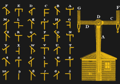
Semaphore towers and coding scheme devised by Claude Chappe. Credit: Govind P. Agrawal, Public Domain
In the late 18th century the Chappe brothers devised and erected a network of semaphore towers in France for military communication. On the top of each tower was a semaphore comprised of two movable wooden arms connected by a crossbar. By adjusting the angle of each arm and the crossbar a total of 196 symbols could be displayed which were observed from the next tower with a telescope. By waiting for the downline station to copy the symbol, the communications protocol already included an ACK signal as a means of flow control. In terms of data rate, the system could reach about 2-3 symbols per minute; taking about two minutes for a symbol to travel from Paris to Lille over 22 stations and 230 km.
In the late 19th and early 20th century, the heliograph was widely used for military communication. It consisted of a mirror that could be pivoted or blocked with a shutter to generate flashes of sunlight and was mostly used to transmit Morse code. Even though the heliograph was rendered obsolete by most armies in the 1940s it was still used by Afghan forces during the Soviet invasion in the 1980s and is still included in many survival kits for emergency signaling.
Bell’s Greatest Invention
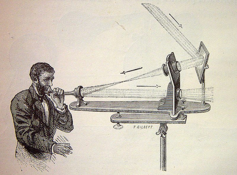
Illustration of the transmitter part of the photophone. Credit: Wikimedia Commons, Public Domain.
Many of you probably know the kind of DIY projects where an audio signal is transmitted by a laser beam which is surprisingly easy to build. The invention goes back to Alexander Graham Bell, who in 1880 invented the photophone which he thought to be his “greatest invention ever made, greater than the telephone”. It could transmit speech wirelessly using a flexible mirror mounted at the end of a speaking tube to modulate the intensity of the reflected sunlight. The receiver part consisted of a selenium photocell at the focus of a parabolic mirror. Bell and his assistant Tainter also build nonelectric receivers using materials coated with lampblack thereby discovering the photoacoustic effect. Even though Bell was immensely proud of his invention up to the point where he wanted to name his second daughter “photophone”, the device never really hit it off. This was mainly because radio wave transmissions as pioneered by Marconi a few years later far surpassed the distance achievable with light and did not require a direct line of sight.
Guiding Light Through Glass
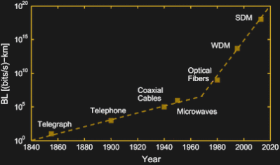
Increase of the bandwidth-distance product throughout history. The squares mark the introduction of new technologies like wavelength-division multiplexing (WDM) and space-division multiplexing (SDM). Credit: Govind P. Agrawal
Apart from a few military projects, telecommunication in the 20th century was mainly conducted via coaxial cables and microwave signals in the relatively low frequency 1-10 GHz range. This was until the development of fiber-optic communications in the 1970s, which was enabled by the invention of low-loss optical fibers and semiconductor lasers.
The main drawback of high-speed communication via coaxial cables is that signals have to be repeated about every kilometer to make up for cable losses. With wireless radio frequency (RF) communication, the repeater spacing can be a lot larger, but in both cases, the bandwidth is limited to ~100 Mbit/s due to the “low” frequency of the RF carrier.
The frequency of visible and infrared light is about 1014 Hz, much higher than the 109 Hz “Gigahertz” frequencies used for RF communication. As a consequence, the optical spectrum is about 2600 times wider, in terms of frequency, than the entire RF spectrum. This broader bandwidth enables much higher data rates.
One of the first applications of fiber optics included the control of short-range missiles through a fiber optic tether attached to the back of the missile that rapidly unspooled during flight. In 1977, General Telephone and Electronics sent the world’s first live telephone traffic through a fiber-optic system at 6 Mbit/s. Today, the worldwide optical fiber network is estimated to span more than 400 million kilometers, close to three times the distance to the sun.
Optical fiber communication soon far surpassed the transmission speeds of RF communication and was further boosted by multiplexing techniques like wavelength-division multiplexing (sending multiple wavelengths down the same fiber), time-division multiplexing (separating signals by their arrival times), or space-division multiplexing (using multi-core or multimode fibers). Using a combination of these techniques, data rates of up to 11 Pbit/s have been demonstrated in the lab. The low light losses of 0.2 dB/km (i.e. the intensity loses only around 5% after 1 km) in modern fiber cables enable repeater spacings of ~80 km.
Internet From Your Light Bulb
We still mostly use the RF spectrum for wireless communication, but there has been some renewed interest in wireless optical. At short distances, this goes under the catchy name LiFi and became a trendy topic about 10 years ago, partly triggered by this TED talk. It advertised the idea of using the already existing infrastructure of regular LED lighting for data transmission.
Some of the advantages being that it is more efficient, more secure against eavesdropping, and enables higher bandwidths. However, the idea of having your WiFi at home transmitted through your light bulbs never really became popular. Arguably one of the reasons might be that having a connection that depends on light shining onto your device is not always considered an advantage. Up to now, LiFi is only used in some industrial applications where electromagnetic interference or security are important issues. But lower bandwidth versions are prime areas for hacking.
Going Long Range
The optical transmission of data over long ranges goes under the name free-space optical communication (FSO). You may remember Facebook’s Aquila drone program, a giant solar-powered vehicle that should stay in the stratosphere for months to beam internet to remote areas. In addition to standard GHz frequency bands for air-to-ground communication, they were also experimenting with free-space optical links. The technology behind this is still similar to Bell`s photophone, although we now use IR lasers instead of sunlight. Shortly after Facebook canceled its Aquila drone program in 2018, it became public that they are working on a similar system that uses satellites instead of drones due to technical difficulties. In September 2020, Facebook’s subsidiary PointView Tech launched the Athena satellite which is supposed to test a laser ground link.
Google (or Alphabet if you prefer) is/was working on similar projects called Loon and Taara. Maya Posh just wrote a more detailed article about Loon. Its goal was to send a network of high-altitude balloons into the stratosphere providing internet access to underserved areas, but the project was shut down a few weeks ago. Within project Loon a 155 Mbit/s laser communication between two balloons more than 100 km apart was achieved. Project Taraa builds on this success and aims at developing towers that use free-space laser communication to deliver 20 Gbit/s connectivity over distances of 20 km. Compared to installing fiber optic cables, this would be a cost-effective and quickly deployable way to bring high-speed connectivity to remote areas.
Transmitter-receiver pair of the open-source project Ronja. Credit: Twibright Labs
Similar systems are already commercially available by a company called Koruza delivering up to 10 Gbit/s, albeit over a modest range of 150 m. Of course, hackers have also played around with the technology. Way back in 2001, the open-source project Ronja provides instructions to build a low-cost transmitter-receiver pair capable of 10 Mbit/s communication over a 1.4 km range. As a transmitter it just uses a standard red LED collimated by large lenses salvaged from magnifying glasses. Ronja works in most weather conditions including rain and snow but fails during fog.
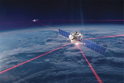
Artist rendering of inter-satellite link via laser communication. Credit: Mynaric
This marks one of the major downsides of FSO. While requiring a direct line of sight makes communication more secure, it also imposes some restrictions. Cloudy weather can make satellite-to-ground communications break up, so microwave signals are considered more viable in this case. However, future internet satellite constellations like SpaceX’s Starlink, OneWeb, or Amazon’s Project Kuiper are likely to use laser communication as a secure, high bandwidth link in between satellites. At the forefront of developing this hardware are the German companies Tesat and Mynaric. Their laser systems currently offer data rates of up to 10 Gbit/s between LEO satellites and ground stations and 1.8 Gbit/s between geosynchronous satellites up to 80,000 km apart.
The advancement of optical communication from the ancient Phryctoriae to modern laser communication was driven by the goal to expand humanity’s interconnectedness. Since the beginning, the communication data rate has increased by ~12 orders of magnitude and culminated in a space race to provide global broadband access via satellite networks. Bringing internet access to underserved areas is certainly a noble goal but we may also question the meaningfulness of enabling ever-higher bandwidths when it is mostly devoured by video streaming. Although there is no strict fundamental limit to the bitrate achievable with optical communication it also interesting to ask the question of what comes beyond, perhaps neutrino communication?
We live in the information age where access to the internet is considered a fundamental human right. Exercising this right does largely rely on the technological advances made in optical communication. Using light to send information has a long history: from ancient Greece, through Claude Chappe’s semaphore towers and Alexander Graham Bell’s photophone, to fiber optical networks and future satellite internet constellations currently developed by tech giants.
Let’s dive a little bit deeper into the technologies that were used to spread information with the help of light throughout history.
Semaphores and Heliographs
Reconstruction of a hydraulic telegraph at Thessaloniki Technology Museum. Credit: Gts-tg, CC BY-SA 4.0
Since light can travel in air much further than sound, visual communication has always been the method of choice to broadcast information over long distances. One of the earliest examples is the Phryctoriae from ancient Greece, a system of towers build on mountaintops that could send messages by lighting torches. Allegedly, this is how the news of the fall of Troy was spread throughout the country. The Greeks came up with different methods of encoding messages. One was to have two groups of five torches where each torch would represent the row and column in a 5×5 matrix of Greek letters known as the Polybius square. The other is the hydraulic telegraph which consisted of a container filled with water and a vertical rod floating within. The rod was inscribed with various messages along its height. When the remote torch signal was received, water from the container was slowly drained until the torch went out again. Through the position of the inscribed rod, the water level could be correlated with a specific message.
Semaphore towers and coding scheme devised by Claude Chappe. Credit: Govind P. Agrawal, Public Domain
In the late 18th century the Chappe brothers devised and erected a network of semaphore towers in France for military communication. On the top of each tower was a semaphore comprised of two movable wooden arms connected by a crossbar. By adjusting the angle of each arm and the crossbar a total of 196 symbols could be displayed which were observed from the next tower with a telescope. By waiting for the downline station to copy the symbol, the communications protocol already included an ACK signal as a means of flow control. In terms of data rate, the system could reach about 2-3 symbols per minute; taking about two minutes for a symbol to travel from Paris to Lille over 22 stations and 230 km.
In the late 19th and early 20th century, the heliograph was widely used for military communication. It consisted of a mirror that could be pivoted or blocked with a shutter to generate flashes of sunlight and was mostly used to transmit Morse code. Even though the heliograph was rendered obsolete by most armies in the 1940s it was still used by Afghan forces during the Soviet invasion in the 1980s and is still included in many survival kits for emergency signaling.
Bell’s Greatest Invention
Illustration of the transmitter part of the photophone. Credit: Wikimedia Commons, Public Domain.
Many of you probably know the kind of DIY projects where an audio signal is transmitted by a laser beam which is surprisingly easy to build. The invention goes back to Alexander Graham Bell, who in 1880 invented the photophone which he thought to be his “greatest invention ever made, greater than the telephone”. It could transmit speech wirelessly using a flexible mirror mounted at the end of a speaking tube to modulate the intensity of the reflected sunlight. The receiver part consisted of a selenium photocell at the focus of a parabolic mirror. Bell and his assistant Tainter also build nonelectric receivers using materials coated with lampblack thereby discovering the photoacoustic effect. Even though Bell was immensely proud of his invention up to the point where he wanted to name his second daughter “photophone”, the device never really hit it off. This was mainly because radio wave transmissions as pioneered by Marconi a few years later far surpassed the distance achievable with light and did not require a direct line of sight.
Guiding Light Through Glass
Increase of the bandwidth-distance product throughout history. The squares mark the introduction of new technologies like wavelength-division multiplexing (WDM) and space-division multiplexing (SDM). Credit: Govind P. Agrawal
Apart from a few military projects, telecommunication in the 20th century was mainly conducted via coaxial cables and microwave signals in the relatively low frequency 1-10 GHz range. This was until the development of fiber-optic communications in the 1970s, which was enabled by the invention of low-loss optical fibers and semiconductor lasers.
The main drawback of high-speed communication via coaxial cables is that signals have to be repeated about every kilometer to make up for cable losses. With wireless radio frequency (RF) communication, the repeater spacing can be a lot larger, but in both cases, the bandwidth is limited to ~100 Mbit/s due to the “low” frequency of the RF carrier.
The frequency of visible and infrared light is about 1014 Hz, much higher than the 109 Hz “Gigahertz” frequencies used for RF communication. As a consequence, the optical spectrum is about 2600 times wider, in terms of frequency, than the entire RF spectrum. This broader bandwidth enables much higher data rates.
One of the first applications of fiber optics included the control of short-range missiles through a fiber optic tether attached to the back of the missile that rapidly unspooled during flight. In 1977, General Telephone and Electronics sent the world’s first live telephone traffic through a fiber-optic system at 6 Mbit/s. Today, the worldwide optical fiber network is estimated to span more than 400 million kilometers, close to three times the distance to the sun.
Optical fiber communication soon far surpassed the transmission speeds of RF communication and was further boosted by multiplexing techniques like wavelength-division multiplexing (sending multiple wavelengths down the same fiber), time-division multiplexing (separating signals by their arrival times), or space-division multiplexing (using multi-core or multimode fibers). Using a combination of these techniques, data rates of up to 11 Pbit/s have been demonstrated in the lab. The low light losses of 0.2 dB/km (i.e. the intensity loses only around 5% after 1 km) in modern fiber cables enable repeater spacings of ~80 km.
Internet From Your Light Bulb
We still mostly use the RF spectrum for wireless communication, but there has been some renewed interest in wireless optical. At short distances, this goes under the catchy name LiFi and became a trendy topic about 10 years ago, partly triggered by this TED talk. It advertised the idea of using the already existing infrastructure of regular LED lighting for data transmission.
Some of the advantages being that it is more efficient, more secure against eavesdropping, and enables higher bandwidths. However, the idea of having your WiFi at home transmitted through your light bulbs never really became popular. Arguably one of the reasons might be that having a connection that depends on light shining onto your device is not always considered an advantage. Up to now, LiFi is only used in some industrial applications where electromagnetic interference or security are important issues. But lower bandwidth versions are prime areas for hacking.
Going Long Range
The optical transmission of data over long ranges goes under the name free-space optical communication (FSO). You may remember Facebook’s Aquila drone program, a giant solar-powered vehicle that should stay in the stratosphere for months to beam internet to remote areas. In addition to standard GHz frequency bands for air-to-ground communication, they were also experimenting with free-space optical links. The technology behind this is still similar to Bell`s photophone, although we now use IR lasers instead of sunlight. Shortly after Facebook canceled its Aquila drone program in 2018, it became public that they are working on a similar system that uses satellites instead of drones due to technical difficulties. In September 2020, Facebook’s subsidiary PointView Tech launched the Athena satellite which is supposed to test a laser ground link.
Google (or Alphabet if you prefer) is/was working on similar projects called Loon and Taara. Maya Posh just wrote a more detailed article about Loon. Its goal was to send a network of high-altitude balloons into the stratosphere providing internet access to underserved areas, but the project was shut down a few weeks ago. Within project Loon a 155 Mbit/s laser communication between two balloons more than 100 km apart was achieved. Project Taraa builds on this success and aims at developing towers that use free-space laser communication to deliver 20 Gbit/s connectivity over distances of 20 km. Compared to installing fiber optic cables, this would be a cost-effective and quickly deployable way to bring high-speed connectivity to remote areas.
Transmitter-receiver pair of the open-source project Ronja. Credit: Twibright Labs
Similar systems are already commercially available by a company called Koruza delivering up to 10 Gbit/s, albeit over a modest range of 150 m. Of course, hackers have also played around with the technology. Way back in 2001, the open-source project Ronja provides instructions to build a low-cost transmitter-receiver pair capable of 10 Mbit/s communication over a 1.4 km range. As a transmitter it just uses a standard red LED collimated by large lenses salvaged from magnifying glasses. Ronja works in most weather conditions including rain and snow but fails during fog.
Artist rendering of inter-satellite link via laser communication. Credit: Mynaric
This marks one of the major downsides of FSO. While requiring a direct line of sight makes communication more secure, it also imposes some restrictions. Cloudy weather can make satellite-to-ground communications break up, so microwave signals are considered more viable in this case. However, future internet satellite constellations like SpaceX’s Starlink, OneWeb, or Amazon’s Project Kuiper are likely to use laser communication as a secure, high bandwidth link in between satellites. At the forefront of developing this hardware are the German companies Tesat and Mynaric. Their laser systems currently offer data rates of up to 10 Gbit/s between LEO satellites and ground stations and 1.8 Gbit/s between geosynchronous satellites up to 80,000 km apart.
The advancement of optical communication from the ancient Phryctoriae to modern laser communication was driven by the goal to expand humanity’s interconnectedness. Since the beginning, the communication data rate has increased by ~12 orders of magnitude and culminated in a space race to provide global broadband access via satellite networks. Bringing internet access to underserved areas is certainly a noble goal but we may also question the meaningfulness of enabling ever-higher bandwidths when it is mostly devoured by video streaming. Although there is no strict fundamental limit to the bitrate achievable with optical communication it also interesting to ask the question of what comes beyond, perhaps neutrino communication?
We live in the information age where access to the internet is considered a fundamental human right. Exercising this right does largely rely on the technological advances made in optical communication. Using light to send information has a long history: from ancient Greece, through Claude Chappe’s semaphore towers and Alexander Graham Bell’s photophone, to fiber optical networks and future satellite internet constellations currently developed by tech giants.
Let’s dive a little bit deeper into the technologies that were used to spread information with the help of light throughout history.
Semaphores and Heliographs
Reconstruction of a hydraulic telegraph at Thessaloniki Technology Museum. Credit: Gts-tg, CC BY-SA 4.0
Since light can travel in air much further than sound, visual communication has always been the method of choice to broadcast information over long distances. One of the earliest examples is the Phryctoriae from ancient Greece, a system of towers build on mountaintops that could send messages by lighting torches. Allegedly, this is how the news of the fall of Troy was spread throughout the country. The Greeks came up with different methods of encoding messages. One was to have two groups of five torches where each torch would represent the row and column in a 5×5 matrix of Greek letters known as the Polybius square. The other is the hydraulic telegraph which consisted of a container filled with water and a vertical rod floating within. The rod was inscribed with various messages along its height. When the remote torch signal was received, water from the container was slowly drained until the torch went out again. Through the position of the inscribed rod, the water level could be correlated with a specific message.
Semaphore towers and coding scheme devised by Claude Chappe. Credit: Govind P. Agrawal, Public Domain
In the late 18th century the Chappe brothers devised and erected a network of semaphore towers in France for military communication. On the top of each tower was a semaphore comprised of two movable wooden arms connected by a crossbar. By adjusting the angle of each arm and the crossbar a total of 196 symbols could be displayed which were observed from the next tower with a telescope. By waiting for the downline station to copy the symbol, the communications protocol already included an ACK signal as a means of flow control. In terms of data rate, the system could reach about 2-3 symbols per minute; taking about two minutes for a symbol to travel from Paris to Lille over 22 stations and 230 km.
In the late 19th and early 20th century, the heliograph was widely used for military communication. It consisted of a mirror that could be pivoted or blocked with a shutter to generate flashes of sunlight and was mostly used to transmit Morse code. Even though the heliograph was rendered obsolete by most armies in the 1940s it was still used by Afghan forces during the Soviet invasion in the 1980s and is still included in many survival kits for emergency signaling.
Bell’s Greatest Invention
Illustration of the transmitter part of the photophone. Credit: Wikimedia Commons, Public Domain.
Many of you probably know the kind of DIY projects where an audio signal is transmitted by a laser beam which is surprisingly easy to build. The invention goes back to Alexander Graham Bell, who in 1880 invented the photophone which he thought to be his “greatest invention ever made, greater than the telephone”. It could transmit speech wirelessly using a flexible mirror mounted at the end of a speaking tube to modulate the intensity of the reflected sunlight. The receiver part consisted of a selenium photocell at the focus of a parabolic mirror. Bell and his assistant Tainter also build nonelectric receivers using materials coated with lampblack thereby discovering the photoacoustic effect. Even though Bell was immensely proud of his invention up to the point where he wanted to name his second daughter “photophone”, the device never really hit it off. This was mainly because radio wave transmissions as pioneered by Marconi a few years later far surpassed the distance achievable with light and did not require a direct line of sight.
Guiding Light Through Glass
Increase of the bandwidth-distance product throughout history. The squares mark the introduction of new technologies like wavelength-division multiplexing (WDM) and space-division multiplexing (SDM). Credit: Govind P. Agrawal
Apart from a few military projects, telecommunication in the 20th century was mainly conducted via coaxial cables and microwave signals in the relatively low frequency 1-10 GHz range. This was until the development of fiber-optic communications in the 1970s, which was enabled by the invention of low-loss optical fibers and semiconductor lasers.
The main drawback of high-speed communication via coaxial cables is that signals have to be repeated about every kilometer to make up for cable losses. With wireless radio frequency (RF) communication, the repeater spacing can be a lot larger, but in both cases, the bandwidth is limited to ~100 Mbit/s due to the “low” frequency of the RF carrier.
The frequency of visible and infrared light is about 1014 Hz, much higher than the 109 Hz “Gigahertz” frequencies used for RF communication. As a consequence, the optical spectrum is about 2600 times wider, in terms of frequency, than the entire RF spectrum. This broader bandwidth enables much higher data rates.
One of the first applications of fiber optics included the control of short-range missiles through a fiber optic tether attached to the back of the missile that rapidly unspooled during flight. In 1977, General Telephone and Electronics sent the world’s first live telephone traffic through a fiber-optic system at 6 Mbit/s. Today, the worldwide optical fiber network is estimated to span more than 400 million kilometers, close to three times the distance to the sun.
Optical fiber communication soon far surpassed the transmission speeds of RF communication and was further boosted by multiplexing techniques like wavelength-division multiplexing (sending multiple wavelengths down the same fiber), time-division multiplexing (separating signals by their arrival times), or space-division multiplexing (using multi-core or multimode fibers). Using a combination of these techniques, data rates of up to 11 Pbit/s have been demonstrated in the lab. The low light losses of 0.2 dB/km (i.e. the intensity loses only around 5% after 1 km) in modern fiber cables enable repeater spacings of ~80 km.
Internet From Your Light Bulb
We still mostly use the RF spectrum for wireless communication, but there has been some renewed interest in wireless optical. At short distances, this goes under the catchy name LiFi and became a trendy topic about 10 years ago, partly triggered by this TED talk. It advertised the idea of using the already existing infrastructure of regular LED lighting for data transmission.
Some of the advantages being that it is more efficient, more secure against eavesdropping, and enables higher bandwidths. However, the idea of having your WiFi at home transmitted through your light bulbs never really became popular. Arguably one of the reasons might be that having a connection that depends on light shining onto your device is not always considered an advantage. Up to now, LiFi is only used in some industrial applications where electromagnetic interference or security are important issues. But lower bandwidth versions are prime areas for hacking.
Going Long Range
The optical transmission of data over long ranges goes under the name free-space optical communication (FSO). You may remember Facebook’s Aquila drone program, a giant solar-powered vehicle that should stay in the stratosphere for months to beam internet to remote areas. In addition to standard GHz frequency bands for air-to-ground communication, they were also experimenting with free-space optical links. The technology behind this is still similar to Bell`s photophone, although we now use IR lasers instead of sunlight. Shortly after Facebook canceled its Aquila drone program in 2018, it became public that they are working on a similar system that uses satellites instead of drones due to technical difficulties. In September 2020, Facebook’s subsidiary PointView Tech launched the Athena satellite which is supposed to test a laser ground link.
Google (or Alphabet if you prefer) is/was working on similar projects called Loon and Taara. Maya Posh just wrote a more detailed article about Loon. Its goal was to send a network of high-altitude balloons into the stratosphere providing internet access to underserved areas, but the project was shut down a few weeks ago. Within project Loon a 155 Mbit/s laser communication between two balloons more than 100 km apart was achieved. Project Taraa builds on this success and aims at developing towers that use free-space laser communication to deliver 20 Gbit/s connectivity over distances of 20 km. Compared to installing fiber optic cables, this would be a cost-effective and quickly deployable way to bring high-speed connectivity to remote areas.
Transmitter-receiver pair of the open-source project Ronja. Credit: Twibright Labs
Similar systems are already commercially available by a company called Koruza delivering up to 10 Gbit/s, albeit over a modest range of 150 m. Of course, hackers have also played around with the technology. Way back in 2001, the open-source project Ronja provides instructions to build a low-cost transmitter-receiver pair capable of 10 Mbit/s communication over a 1.4 km range. As a transmitter it just uses a standard red LED collimated by large lenses salvaged from magnifying glasses. Ronja works in most weather conditions including rain and snow but fails during fog.
Artist rendering of inter-satellite link via laser communication. Credit: Mynaric
This marks one of the major downsides of FSO. While requiring a direct line of sight makes communication more secure, it also imposes some restrictions. Cloudy weather can make satellite-to-ground communications break up, so microwave signals are considered more viable in this case. However, future internet satellite constellations like SpaceX’s Starlink, OneWeb, or Amazon’s Project Kuiper are likely to use laser communication as a secure, high bandwidth link in between satellites. At the forefront of developing this hardware are the German companies Tesat and Mynaric. Their laser systems currently offer data rates of up to 10 Gbit/s between LEO satellites and ground stations and 1.8 Gbit/s between geosynchronous satellites up to 80,000 km apart.
The advancement of optical communication from the ancient Phryctoriae to modern laser communication was driven by the goal to expand humanity’s interconnectedness. Since the beginning, the communication data rate has increased by ~12 orders of magnitude and culminated in a space race to provide global broadband access via satellite networks. Bringing internet access to underserved areas is certainly a noble goal but we may also question the meaningfulness of enabling ever-higher bandwidths when it is mostly devoured by video streaming. Although there is no strict fundamental limit to the bitrate achievable with optical communication it also interesting to ask the question of what comes beyond, perhaps neutrino communication?
These days, there’s a huge variety of screens on the market for use with microcontrollers. OLEDs and graphic LCDs abound, while e-ink devices tempt the user with their clean look and low energy consumption. However, for many purposes, the humble HD44780 character LCD does the job just fine. If you’re using such a device, you might want to implement a simple menu system, and in that case, [MyHomeThings] has you covered.
The menu code is simple to modify and implement. It allows the user to define a certain number of menu items, along with button labels and functions to be executed with button presses. By default, it’s set up to work with left and right function buttons, with up and down buttons to toggle through the menu’s various entries. This suits the commonly available Arduino shields which combine a 16×2 character LCD with a set of four tactile buttons in a cross formation. However, modifying the code to use an alternate button scheme would be simple for those eager to tweak things to their liking.
For the absolute beginner to programming, it’s a great way to put together a simple interface for your microcontroller projects. It’s the sort of thing you might use if you’d built a do-everything Arduino handheld device, as we’ve seen built before. If you find text menus too archaic for your purposes, though, be sure to sound off with your favourite solutions in the comments.
While not a Cabinet position, the NASA Administrator is nominated by the president of the United States and tasked with enacting their overall space policy. As such, a new occupant in the White House has historically resulted in a different long-term directive for the agency. Some presidents have wanted bold programs of exploration, while others have directed NASA to follow a more reserved and economical path, with the largest shifts traditionally happening when the administration changes hands between the parties.
So it’s no surprise that the fate of Artemis, a bold program initiated by the previous administration that aims to establish a sustainable human presence on the Moon, has been considered uncertain since the November election. But the recent announcement that SpaceX has been awarded a $331.8 million contract to launch the first two modules of the lunar Gateway station, an orbital outpost that will serve as a rallying point for astronauts coming and going to the Moon’s surface, should help quell some concerns. While the components still aren’t slated to fly until 2024 at the earliest, it’s a step in the right direction and strong indicator that the new administration plans on seeing Artemis through.
Two For the Price of One
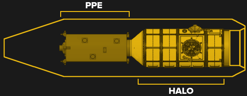
The contracted launch is unique in that SpaceX is being tasked with launching two separate modules, the Power and Propulsion Element (PPE) built by Maxar Technologies, and the Habitation and Logistics Outpost (HALO) from Northrop Grumman, on the same rocket. These two core Gateway components, which essentially make up a miniature space station themselves, will be mated on the ground at Kennedy Space Center and tested for several months before being loaded onto a Falcon Heavy.
While the mass of these two modules is well within the capabilities of the Falcon Heavy, their combined length will require SpaceX to develop an extended payload fairing. They will also need to build a new mobile gantry at launchpad 39A that will allow for the modules to be attached to the rocket vertically, rather than horizontally as is the case with all current Falcon and Falcon Heavy launches. The new fairing and integration facility naturally represent a considerable investment by SpaceX, but long term, these changes will enable the Falcon Heavy to carry large national security satellites for the Pentagon and provide the company with a lucrative new revenue stream.
Originally the PPE and HALO modules would have flown on two separate rockets, possibly even by different launch providers, needing an autonomous docking maneuver after their rendezvous at the Moon. But to reduce costs and get the Gateway operational sooner, it was decided to send them both at the same time. This does introduce the possibility that a failure could result in the loss of both modules, but since their functionality is so intrinsically linked anyway, NASA believes it’s worth the risk to expedite the program.
Deep Space Legacy
As with many NASA projects, Gateway is the end result of a long and winding development process. The PPE is an evolution of the electric propulsion module intended for the agency’s now-canceled Asteroid Redirect Mission, and the idea of a small self-contained space station being sent to lunar orbit has its roots in the Deep Space Habitat concept that engineers have been working on since the retirement of the Shuttle refocused NASA’s long-term goals on activities outside of low Earth orbit.
Orion and cargo atop the EUS.
Back in 2017, NASA was calling this concept the Deep Space Gateway, and envisioned it as a stepping stone to distant destinations such as Mars. The three initial modules of the Deep Space Gateway would be launched into orbit around the Moon using the upgraded Block 1B variant of the Space Launch System. In this configuration, the booster would use the Exploration Upper Stage (EUS) and have enough power to carry a station module and Orion crew capsule in one launch. At that point, commercial launches were only being considered for less critical components which would be added on later, such as an airlock or additional laboratory module.
But the EUS, much like the Space Launch System itself, is taking far longer to bring online than anyone at NASA anticipated. Despite being in development since 2014, the design only made it through the final review stage a few months ago, and actual flight hardware isn’t expected to be completed until at least 2025. This would put it beyond all the currently scheduled Artemis missions, though if everything goes according to plan, by that time both Gateway and a potential outpost on the lunar surface will be able to benefit from the enhanced cargo capabilities of the SLS.
Competition, or Lack Thereof
Launching large objects to the Moon and Mars is arguably why NASA is building their Space Launch System in the first place, and yet according to the current timeline, Gateway will be up and operational before the megarocket is capable of delivering any noteworthy amount of cargo. Much like the recent announcement that NASA will fly the Europa Clipper on a commercial booster, this is another example of the agency’s homegrown vehicle losing a high profile mission to a smaller and cheaper rocket.
Starship would land on the Moon independently.
At this point, one of the few clear uses for the Space Launch System and its EUS in the context of the Artemis program is for delivering large landers to the Moon. Whether they go directly into lunar orbit or rendezvous with the Gateway, two out of the three commercial Human Landing Systems selected by NASA are designed to be launched aboard an SLS Block 1B. Although as a contingency, their principle components can also be carried on smaller rockets and assembled in orbit.
But the third lander, proposed by SpaceX, is a variant of their Starship vehicle that can take off from Earth and land on the Moon under its own power. As a completely independent system, it doesn’t require the Gateway or SLS to complete its mission. On one hand, this is a clear advantage given how frequently NASA’s own plans miss their deadlines and slip further into the future. But there’s certainly an argument to be made against pinning so much of the Artemis program on a single contractor.
A long-term sustainable program for lunar exploration and utilization should include a fleet of boosters and spacecraft that are independently designed, manufactured, and operated. Yet as of right now, SpaceX is the sole company responsible for both launching Gateway and sending regular resupply missions to it. Whether it’s Old Space or New Space, there’s an inherent risk in relying so completely on any one entity. But unless something changes in the next few years, it looks like that’s exactly the situation NASA’s Artemis program could find itself in.
It’s recently come to our attention that a company by the name of Nourished has carved out a niche for themselves by offering made-to-order gummy vitamins produced with their own custom designed 3D printers. Customers can either select from an array of pre-configured “stacks”, or dial in their own seven layers of gelatinous goodness for a completely bespoke supplement.
Now we can’t vouch for whether or not taking a custom supplement like this is any better than just popping a traditional multi-vitamin, but we’ll admit the hardware Nourished has developed is pretty interesting. As briefly seen in the video after the break, large syringes are filled with the seven different vitamin suspensions, and then loaded into what appears to be a heated chamber for extrusion. This is not unlike other food-grade 3D printers we’ve seen, such as the Cocoa Press.
It looks like all of the syringes are being depressed simultaneously with a plate and a pair of beefy lead screws, hinting that the order in which the layers are placed down must be different for each nozzle. A blog post on the company’s site from early last year shows a wildly different machine being used to produce the vitamins, hinting that either their core technology is changing rapidly, or that there are different lines for running off the customized stacks versus the standard formulations.
Interestingly, this is very similar to a concept floated by the U.S. Army’s Combat Feeding Directorate (CFD) back in 2014. They reasoned that a 3D printer could be used to produce meal bars that were customized for each soldier’s personal nutritional needs. Being largely impractical for the battlefield, the program didn’t get very far. But thanks to consumers who are willing to pay the premium that Nourished is charging for this service, it seems the idea has turned into a lucrative business model.
Sensors aren’t just limited to the electrical, mechanical, or chemical realm. Up until 1986, canaries were used as Carbon Monoxide detectors, and food tasters are still used by some heads of state. These so-called sentinel species have been known and used for decades if not centuries. But recent projects using clams to detect water pollution are providing real-time electronic feedback. They are using the species Actinonaias ligamentina, which, as you no doubt recall, was declared “Mussel of the Month” by the University of Wisconsin’s MUSSEL Project back in January 2010. They are more commonly known as mucket clams or mucket mussels, and are particularly sensitive to water pollution — they will clam-up, so to speak, in the presence of contaminated water.
Clam Sensor Wiring Mississippi River Project
Several municipalities along the Mississippi River installed clam-based sensors back in 2015, and another system was installed in the Anacostia River Estuary in 2011. Polish director Julia Pekla produced a documentary about the clam-based sensors installed at the Dębiec Water Treatment Plant on the Wisła River near Warsaw which has been in operation since 1994. Her documentary is titled “Gruba Kaśka (Fat Kathy)” and won the In Vivo Award at the 2020 Imagine Science Film’s 13th annual film festival (see trailer below).
As shown in the lead photo, a simple electrical contact is mounted on each clam, which closes a circuit with the base contact when the shell is clamped shut. The systems along the Mississippi River use multiple clams, 11 in Minneapolis Minnesota and 16 in Moline Illinois. The system in Poland uses eight clams — when four or more clams are in agreement the system automatically shuts down and alerts the operators. These clams only work for three months, after which they are put into retirement with a mark so they won’t be required to serve again.
It might be difficult to imagine in our modern HDMI Utopia, but there was a time when game consoles required proprietary cables to connect up to your TV. We’re not just talking about early machines like the NES either, turn of the millennium consoles like the PlayStation 2, Gamecube, and the original Xbox all had weirdo A/V ports on the back that were useless without the proper adapter.
But thanks to the efforts of [Taylor Burley], you can now upgrade your Slim PS2 with native HDMI capability. It’s not even a terribly difficult modification, as these things go. Sure there’s a lot of soldering involved to run from the console’s A/V connector to the commercially-made HDMI dongle he’s hidden inside the case, but at least it’s straightforward work.
Tapping into the console’s A/V connector.
As [Taylor] shows in the video after the break, all you have to do is remove the proprietary connector from the HDMI adapter dongle, and wire it directly into the console’s A/V port with a bit of ribbon cable. There are only 8 pins in the connector that you need to worry about, and the spacing is generous enough that there’s no problem getting in there with your iron and some standard jumper wires. You’ve also got to pull 5 V from the board to power the adapter, but that’s easy enough thanks to the system’s nearby USB ports.
There’s a perfect spot to mount the adapter board next to the console’s Ethernet connector, and once that’s tacked down with a bit of adhesive, the only thing left to do is cut a hole in the back of the enclosure for the HDMI port and snip away a bit of the metal RF shield. Presumably the same modification could be done on the original “fat” PS2, though you’ll be on your own for finding a suitable place to mount the board.

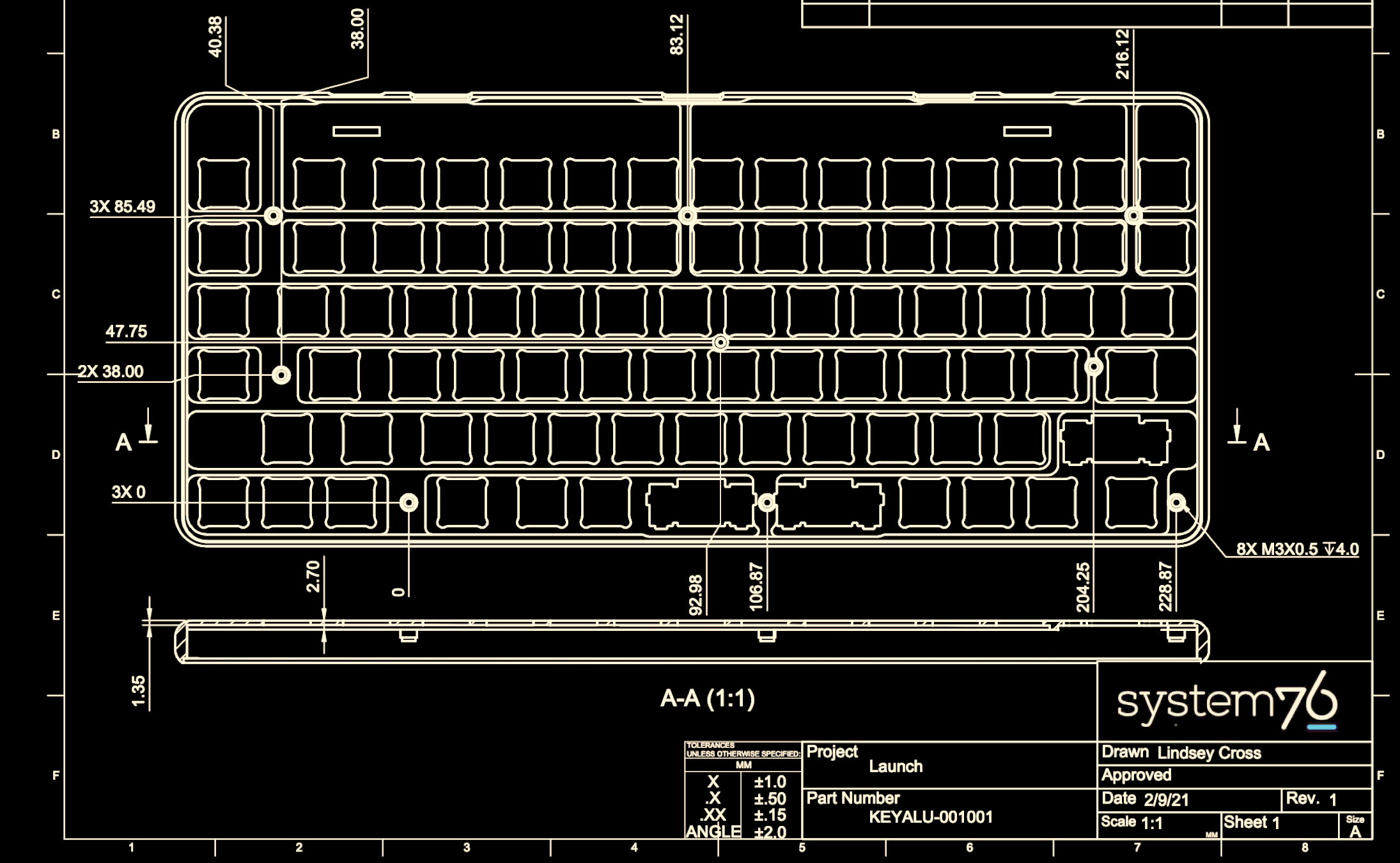
 Feature wise all the usual hallmarks of a well designed keyboard are here. The Launch uses hostswap sockets to make it easy to install the usual Cherry MX compatible switch options, and includes per-key RGB backlighting courtesy of SK6805 LEDs. The ATmega32U4 runs the popular and extremely capable QMK firmware instead of something bespoke, so it should be easy to customize to the user’s desire.