When it comes to building quirky clocks that also double up as beautiful animated sculptures, [Ekaggrat Singh Kalsi] is a master par excellence. His latest offering is the Getula, a time piece inspired by an old, discarded bicycle chain, while the name seems inspired by the chain kingsnake — Lampropeltis getula – due to its snake like movements. Getula shows time by manipulating eight short pieces of chain to show four digits representing hours and minutes. But wrangling a flexible piece of chain to morph in to numerals turned out to be a far more complex endeavour than he bargained for, and he had to settle for a few compromises along the way.
He could not use real bicycle chains because they are too flexible and heavy, which made it impossible for them to hold the shapes he desired. Instead, he designed custom 3D printed chains similar to drag link chains used for cable management. For rigidity, he added O-rings in the chain joints to increase friction. But even this was not sufficient to completely form each digit using a single piece of chain.
The compromise was to use two pieces of chain per digit, which results in a more artistic expression of time keeping. Each piece of chain is pushed or pulled using stepper motors, and bent in to shape using servos. The end result is a mesmerising dance of chain links, steppers and servos every minute, around the clock.
Designing the clock was no trivial exercise, so [Ekaggrat] improved it over a couple of iterations. There are four modular blocks working in synchronism — each consisting of an Arduino Nano, two stepper motor drives with motors and two servos. Each chain has an embedded magnet at its start, which is sensed by a hall sensor to initialise the chain to a known position. A DS1307 RTC module provides timekeeping. The project is still work in progress, and [Ekaggrat] has managed to finish off just one module out of four — giving us a tantalizing glimpse of Getula welcoming 2021.
Back in 1990 [Benjamin Zotto] wrote – while in elementary school – a dog racing game called Wonderland 2. The BASIC source code and images for the game were stored on a single ProDOS formatted, soft-sectored 5.25″ floppy disk. Fast-forward thirty years to today and [Benjamin] found to his dismay that ProDOS could no longer read the floppy, giving an I/O error. Not deterred, he set about to recover the data, as documented in this Twitter thread.
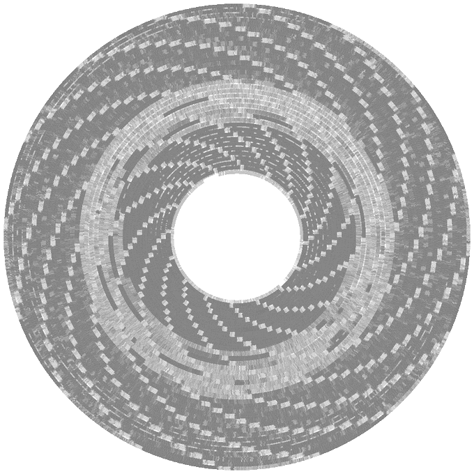
Applesauce visualization of the patterns on the corrupted disk, with soft-sectoring spiral arms.
The gist of the story is that the floppy disk’s surface could still be scanned with help from the aptly named Applesauce Floppy Drive Controller, which got the following visualization of the magnetic patterns on the disk surface:
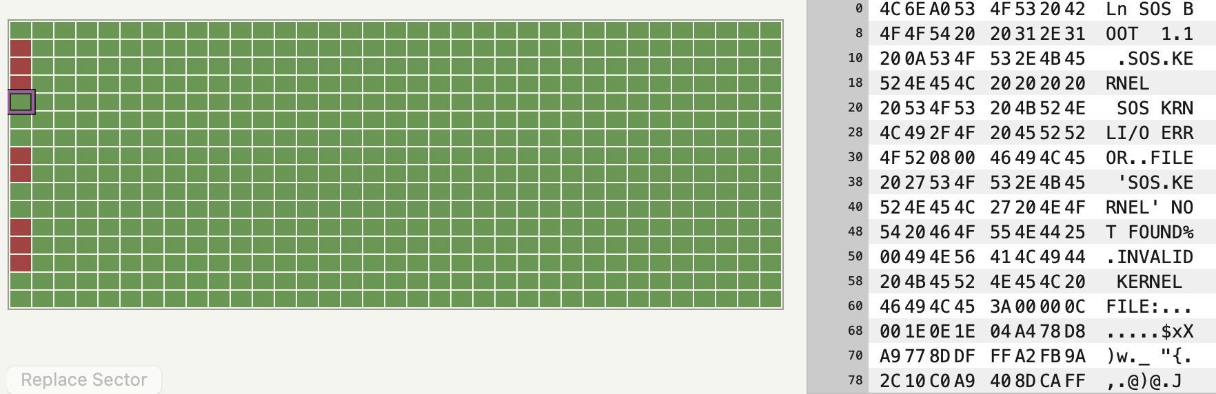
This data could then be analyzed sector by sector, with the bad sectors and the cause for ProDOS flaking out with its reading attempts here marked in red.
Checking the data recovered so far confirmed that it was a ProDOS disk. It also confirmed that the sector containing the directory listing was shot. This required diving into the technical reference manual for ProDOS and its filesystem to figure out how to reconstruct the directory layout. This required figuring out the offsets and sizes of the files, assisted by knowing what was likely on the disk, and having some bits and pieces of the original volume listing still intact. This allowed for the directory volume to be rebuilt, one byte at a time.
Sectors on the disk, with bad sectors in red.
At the end of that arduous and highly educational journey success waited, and [Benjamin] was once again able to relive his memories of 1990s BASIC and hand-drawn bitmap graphics.
Back in 1990 [Benjamin Zotto] wrote – while in elementary school – a dog racing game called Wonderland 2. The BASIC source code and images for the game were stored on a single ProDOS formatted, soft-sectored 5.25″ floppy disk. Fast-forward thirty years to today and [Benjamin] found to his dismay that ProDOS could no longer read the floppy, giving an I/O error. Not deterred, he set about to recover the data, as documented in this Twitter thread.
Applesauce visualization of the patterns on the corrupted disk, with soft-sectoring spiral arms.
The gist of the story is that the floppy disk’s surface could still be scanned with help from the aptly named Applesauce Floppy Drive Controller, which got the following visualization of the magnetic patterns on the disk surface:
This data could then be analyzed sector by sector, with the bad sectors and the cause for ProDOS flaking out with its reading attempts here marked in red.
Checking the data recovered so far confirmed that it was a ProDOS disk. It also confirmed that the sector containing the directory listing was shot. This required diving into the technical reference manual for ProDOS and its filesystem to figure out how to reconstruct the directory layout. This required figuring out the offsets and sizes of the files, assisted by knowing what was likely on the disk, and having some bits and pieces of the original volume listing still intact. This allowed for the directory volume to be rebuilt, one byte at a time.
Sectors on the disk, with bad sectors in red.
At the end of that arduous and highly educational journey success waited, and [Benjamin] was once again able to relive his memories of 1990s BASIC and hand-drawn bitmap graphics.
Back in 1990 [Benjamin Zotto] wrote – while in elementary school – a dog racing game called Wonderland 2. The BASIC source code and images for the game were stored on a single ProDOS formatted, soft-sectored 5.25″ floppy disk. Fast-forward thirty years to today and [Benjamin] found to his dismay that ProDOS could no longer read the floppy, giving an I/O error. Not deterred, he set about to recover the data, as documented in this Twitter thread.
Applesauce visualization of the patterns on the corrupted disk, with soft-sectoring spiral arms.
The gist of the story is that the floppy disk’s surface could still be scanned with help from the aptly named Applesauce Floppy Drive Controller, which got the following visualization of the magnetic patterns on the disk surface:
This data could then be analyzed sector by sector, with the bad sectors and the cause for ProDOS flaking out with its reading attempts here marked in red.
Checking the data recovered so far confirmed that it was a ProDOS disk. It also confirmed that the sector containing the directory listing was shot. This required diving into the technical reference manual for ProDOS and its filesystem to figure out how to reconstruct the directory layout. This required figuring out the offsets and sizes of the files, assisted by knowing what was likely on the disk, and having some bits and pieces of the original volume listing still intact. This allowed for the directory volume to be rebuilt, one byte at a time.
Sectors on the disk, with bad sectors in red.
At the end of that arduous and highly educational journey success waited, and [Benjamin] was once again able to relive his memories of 1990s BASIC and hand-drawn bitmap graphics.
There is a boring part of every computer introduction class that shows how a computer is made up of input, output, and processing. Maybe it wouldn’t be so boring if the input device was a nunchuck. [Brian Lough] thinks so and he belligerently asserts that nunchucks are the best input device ever. With a simple connection to a Wii controller and an associated library, you get access to an analog joystick, two buttons, and an accelerometer.
The nunchuck is meant to plug into a Wii controller and the connection is I2C, so that’s trivial to interface to an Arduino or other small microcontroller. The only issue is making the connection. We might have just snipped the wires, but [Brian] prefers to use a small breakout board that plugs into the stock connector and provides solder points for your own cable. There are options for the breakout boards, and [Brian] has his own design that you can get from OSHPark for about a buck for three boards. You can also just jam wire into the connector, but that’s not always robust.
The controllers use 3.3V which isn’t unusual these days. There’s an available library that makes reading them easy. Obviously, not all applications will be a natural fit, but we did like them on the Tetris game [Brian] created. It is also natural for any kind of motion control like his gimbal mount example.
Even if you don’t have junk Wii controllers hanging around, they are common enough on the resale market and you can buy new third-party controllers without spending much. Makes us sorry we threw away ours in the last move.
If you want to get serious hacking a nunchuck, you can go full custom. Or, just give up, and turn one into a Raspberry Pi.
There is a boring part of every computer introduction class that shows how a computer is made up of input, output, and processing. Maybe it wouldn’t be so boring if the input device was a nunchuck. [Brian Lough] thinks so and he belligerently asserts that nunchucks are the best input device ever. With a simple connection to a Wii controller and an associated library, you get access to an analog joystick, two buttons, and an accelerometer.
The nunchuck is meant to plug into a Wii controller and the connection is I2C, so that’s trivial to interface to an Arduino or other small microcontroller. The only issue is making the connection. We might have just snipped the wires, but [Brian] prefers to use a small breakout board that plugs into the stock connector and provides solder points for your own cable. There are options for the breakout boards, and [Brian] has his own design that you can get from OSHPark for about a buck for three boards. You can also just jam wire into the connector, but that’s not always robust.
The controllers use 3.3V which isn’t unusual these days. There’s an available library that makes reading them easy. Obviously, not all applications will be a natural fit, but we did like them on the Tetris game [Brian] created. It is also natural for any kind of motion control like his gimbal mount example.
Even if you don’t have junk Wii controllers hanging around, they are common enough on the resale market and you can buy new third-party controllers without spending much. Makes us sorry we threw away ours in the last move.
If you want to get serious hacking a nunchuck, you can go full custom. Or, just give up, and turn one into a Raspberry Pi.
We’re not sure what we like better about this upcycled trapper hat — that [ellygibson] made it as a tribute to Holden Caulfield, the anti-hero of the classic teen angst novel The Catcher in the Rye, or the fact that she made it out of a skirt that cost a dollar from the thrift store. Oddly enough, one dollar is exactly what Holden paid for his hat in the book.
To make this hat, [elly] started by measuring the circumference of her head, then used math to figure out the radius of the circle for the top part. She made a prototype first to get the fit right, then cut the pieces from the skirt and the lining pieces from black flannel. We love that [elly] used the tiny pocket from the skirt in one of the ear flaps, because it will surely come in handy one day.
[elly] doesn’t provide pattern pieces, but that’s okay — between the explanation of how she arrived at the hat band circumference and the step-by-step instructions, it should be easy to make one of these for yourself from whatever fabric you’ve got.
[Carl] wanted to put his force sensors on a transparent PCB and had to ask his board vendor for a special sample. Flexible PCBs are available on transparent substrates made of PET, but they are not as common as polyimide boards. As [Carl] found out, these boards are a bit thicker, a bit less flexible, and don’t hold up to very high heat as well as the standard boards. Undeterred, he designed a 3D Christmas tree using the clear boards. The result that you can see in the video below looks pretty good and would have been hard to duplicate with conventional means.
When you build the board it is as a flat spiral, but lifting it in the center allows it to expand into a conical tree shape. The circuit itself is just an LED blinker, but the flexible board is the interesting part.
Don’t let the heat put you off, as though the boards deformed at temperatures around 215C and require careful soldering, your projects will probably not run at that temperature.
There was a time when any sort of flexible PCB was a big project. Now it is easily done and not particularly expensive. [Carl] mentions he violates some best practices for the sake of speed and aesthetics, but the result works fine and it looks pretty cool.
We know what you’re thinking. It’s a bad power supply, of course it was capacitors to blame. But even if we all intuitively know at this point that bad caps are almost always the culprit when a PSU gives up the ghost, it’s not always easy to figure out which one is to blame. Which is why this deep dive into a failed ETK450AWT by [eigma] is worth a look.
The first sign of trouble was when the computer would unexpectedly reboot with nothing in the system logs to indicate a problem. Eventually, [eigma] noticed a restart before the operating system even loaded, which confirmed the hardware was to blame. A quick look at the PSU output with a voltmeter showed things weren’t too far out of spec, but putting an oscilloscope on the 12 V line uncovered a nasty waveform that demanded further investigation.
Connecting all the dots.
By carefully following traces and comparing with common PSU diagrams, [eigma] was able to identify the SG5616 IC that checks the various voltages being produced by the PSU and generates the PWR_OK signal which tells the motherboard that everything is working normally. As before, all of the DC voltages at this chip seemed reasonable enough, but the pin that was measuring AC voltage from the transformer was showing the same ripple visible on the 12 VDC line.
Even more digging uncovered that the transformer itself had a control IC nestled away. The 13 VDC required by this chip to operate is pulled off the standby transformer by way of a Zener diode and a couple capacitors, but as [eigma] soon found, the circuit was producing another nasty ripple. Throwing a few new capacitors into the mix smoothed things out and got the PSU to kick on, but that’s not quite the end of the story.
Pulling the capacitors from the board and checking their values with the meter, [eigma] found they too appeared to be within reasonable enough limits. They even looked in good shape physically. But with the help of a signal generator, he was able to determine their equivalent series resistance (ESR) was way too high. Case closed.
We know what you’re thinking. It’s a bad power supply, of course it was capacitors to blame. But even if we all intuitively know at this point that bad caps are almost always the culprit when a PSU gives up the ghost, it’s not always easy to figure out which one is to blame. Which is why this deep dive into a failed ETK450AWT by [eigma] is worth a look.
The first sign of trouble was when the computer would unexpectedly reboot with nothing in the system logs to indicate a problem. Eventually, [eigma] noticed a restart before the operating system even loaded, which confirmed the hardware was to blame. A quick look at the PSU output with a voltmeter showed things weren’t too far out of spec, but putting an oscilloscope on the 12 V line uncovered a nasty waveform that demanded further investigation.
Connecting all the dots.
By carefully following traces and comparing with common PSU diagrams, [eigma] was able to identify the SG5616 IC that checks the various voltages being produced by the PSU and generates the PWR_OK signal which tells the motherboard that everything is working normally. As before, all of the DC voltages at this chip seemed reasonable enough, but the pin that was measuring AC voltage from the transformer was showing the same ripple visible on the 12 VDC line.
Even more digging uncovered that the transformer itself had a control IC nestled away. The 13 VDC required by this chip to operate is pulled off the standby transformer by way of a Zener diode and a couple capacitors, but as [eigma] soon found, the circuit was producing another nasty ripple. Throwing a few new capacitors into the mix smoothed things out and got the PSU to kick on, but that’s not quite the end of the story.
Pulling the capacitors from the board and checking their values with the meter, [eigma] found they too appeared to be within reasonable enough limits. They even looked in good shape physically. But with the help of a signal generator, he was able to determine their equivalent series resistance (ESR) was way too high. Case closed.
Even if you aren’t an electronics person, you probably have a working knowledge of circuit breakers. When the lights go out, you find the circuit breaker and flip it back to the on position. Most people understand, too, that the breaker will trip if you overload the circuit with too many things plugged in or with an accidental short circuit. But how does this common device actually work? Keep in mind, circuit breakers need to be super reliable and have been around long enough that you can imagine they are pretty low tech. [Learn Engineering] has a very clear video about what goes on inside a circuit breaker that’s worth the eight minutes to watch. You can see the video below.
The handle is a mechanical engineering marvel, using two springs and a special design so that even a tiny force will cause it to snap to the off position. That takes care of a human tripping it. However, you have two other cases where you want to turn it off: overload and short circuit.
The short circuit case is easy to detect with an electromagnet that will have a strong magnetic field when so much current flows. However, the overload case isn’t that abrupt. For that, the breaker uses a bimetalic coil that expands as it heats.
There is one other detail. When the breaker opens at high currents, an arc forms. There’s a special component inside to help dissipate the arc. There’s a lot going on in that little box.
Of course, nowadays there are fancier breakers that detect arcing as well as shorts and overloads. We’ve also seen at least one other breaker teardown in the past.
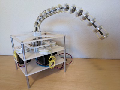
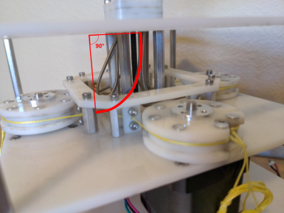
I fell in love with cable driven mechanisms a few years ago and put together some of my first mechanical tentacles to celebrate. But only after playing with them did I start to understand the principles that made them work. Today I want to share one of the most important equations to keep in mind when designing any device that involves cables, the capstan equation. Let some caffeine kick in and stick with me over the next few minutes to get a sense of how it works, how it affects the overall friction in your system, and how you can put it to work for you in special cases.
A Quick Refresher: Push-Pull Cable Driven Mechanisms
But first: just what exactly are cable driven mechanisms? It turns out that this term refers to a huge class of mechanisms, so we’ll limit our scope just to push-pull cable actuation systems.
These are devices where cables are used as actuators. By sending these cables through a flexible conduit, they serve a similar function to the tendons in our body that actuate our fingers. When designing these, we generally assume that the cables are both flexible and do not stretch when put in tension.
Since these cables are flexible, they can only exhibit a pull force, not a push, so cables often come in pairs to actuate along both directions. Here, they’ll be opening and closing the jaws of the Chomper.
Here, the joystick controls the yellow jaw of our Chomper by means of two cables, either of which can be put in tension. One of the key elements behind cables is the ability to reroute the direction of the applied force by controlling the cable through thin sheaths or conduits like so:
In this setup above, we can still control the Chomper remotely through the joystick and the mechanical control cables, albeit, with some added friction. Ideally, the conduits routing the cable are extremely flexible and do not compress when a compressive force is applied to them. That might sound like sort of magic component–but it’s not! It’s actually just a long skinny extension spring like these parts from DR Templeman. These parts go by a few names: continuous-length extension spring, spring guide… but I’ll generally refer to them as spring guide when referring to them in animatronics projects. This spring guide is extremely flexible, but also resistant to being compressed since it’s made from stainless steel.
If the above example seems a bit far-fetched, take the braking system on your bicycle as an example of a cable-actuated setup. Here, your hand squeezes the brakes on one end of the bike, which moves a length of cable running through a sheath on your bike, which moves your brake calipers and eventually squeezes the rim of your wheel hub to slow you down. Instead of a second conduit, however, an extension spring provides the return force to open the brake calipers when we release the handle.
All in all, these mechanisms really shine in situations requiring tight clearances, backlash-free control, and a limited angle of rotation. Properly designed, cable drives can be made to be both backlash free and back-drivable. But they’re no miracle elixir here. They have limits, and the capstan equation is fundamental to understanding your biggest challenge when it comes to their design: friction.
You vs. Friction: Conduit Edition
Wouldn’t it be neat if we could control anything remotely, using mechanical control cables from a distance? I totally agree! But it’s worth asking, what’s preventing us from weaving our cable and conduit in and out of some arbitrary setup? The answer comes down to friction. Friction is our enemy here, putting a limit to how much we can physically bend the conduit before it becomes too difficult to move. But the specific relationship to our problem is rather unintuitive! To build up a rigorous understanding of how friction affects the cable, let’s start by working a sample problem.
Let’s get rid of the conduit for a minute and start with a crude model using just two ingredients: a cable and a cylinder. In the image below, we’ve wrapped the cable partially around a fixed cylinder, and we’ve put both ends of the cable in tension so that the cable hugs the cylinder. Keep in mind that the cylinder can’t rotate, so if we wanted to move the cable, we’d have to fight friction here and rub up against the cylinder.
Now let’s start by putting both sides in tension with two tension values: TLoad and THold. We’ll keep the tension constant on THold, but let’s slowly increase value of TLoad. If our cylinder were actually frictionless pulley, trying to create a mismatch in tension would be impossible; the tension on one side would always be equal to the tension on the other side. But because our cylinder is fixed, it is, in fact, possible to increase the tension on one side while keeping the tension on the other side constant, all while the rope doesn’t slip in the process. This happens because static friction on the cylinder is acting against the tension increase up to a certain limit.
If we zoom in on a cross section of rope to examine the forces acting on a small sliver, we can see how static friction is acting against TLoad, which is equalizing the tension mismatch so that the cable doesn’t slip.
Free body diagram of an infinitesimal cross section of cable measuring with infinitesimal angle dθ.
So here’s the big question: for a fixed value of THold on one side of the cylinder, just how much am I allowed to increase the TLoad on the other side before the cable slips and starts rubbing on the cylinder? (Heads-up! The full derivation requires some calculus and differential equation knowledge, but, for the curious, have a look at this PDF.)
TL;DR: the answer is the Capstan Equation. It tells us that, for a given holding tension on one side, the maximum amount of tension we can put on the other side of the cable without slipping is given by:
Moving both T’s over to one side gives us something a little more interesting: a ratio between two tensions.
Let’s have a look at this equation’s inputs. µs is the cable’s coefficient of static friction, a material property that we can look up in a table or material datasheet. θ is the total bend angle between your two tension vectors, TLoad. and THold, measured in radians. TL and TH are the magnitudes of each respective tension value.
Also, an important side note: the bend angle θ is cumulative. In other words, if you add another fixed cylinder into the mix, you have to add up the total bend angle there too. That’s true even if the angle bends in the opposite direction as shown below:
So the total angle that we’d put in the capstan equation is given by θ1+ θ2.
What’s key here is that only two properties, bend angle and coefficient of static friction, will dictate just how much extra tension we can add on one side before the whole setup slips. So what can we glean from this equation?
The first key takeaway is that the cylinder size has no effect on the amount of friction mismatch. In other words, a small radius cylinder will produce the same resulting value that a large radius cylinder would, provided that the overall bend angles are the same. That’s not intuitive! I should mention, though: the equation above assumes that the cable is infinitely flimsy, which is a good approximation unless our bending radius is really small, like a few multiples of the cable diameter. In that case, the force required to bend the cable does matter. But, for most situations, we can ignore it.
Another key takeaway is that the relationship is exponentially related to the bend angle! So while one wrap around the cylinder might not add much friction, adding a second wrap more-than-doubles the maximum tension ratio between the two cable ends. For an example, with a cable who’s µs = 0.3, two wraps is 6.6 times more friction than one wrap. Three wraps is 43.4 times more friction than one wrap [math link]. But if our µs = 0.2, than three wraps is only 12.3 times as much friction as one wrap. In short, exponential relationships are not intuitive and add up quickly, and picking a cable with a coefficient of friction that’s as small as possible (like this nylon-coated cable) is key to keeping the excess friction low.
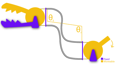
On its own, this example feels pretty obtuse, so let’s tie it back to our original problem with our cable-driven chomper using conduits. To translate the takeaways from problem to our setup, we simply substitute the cylinders above with conduit, and–voila–the exact same equation applies to this setup also! Since both the cylinder and the conduit are fixed, the capstan equation applies to this situation too. Here the cumulative bend angle is coming from the total bend of the cable that’s in tension.
Notice that I only marked angles θ1 and θ2 on one conduit, not both. That’s on purpose. For a for a clockwise torque applied to the joystick, only one cable is being put in tension; the other one goes slack. In other words, only the bends on the cable in tension add to the friction cost. If we applied a torque on the handle in the other direction, the friction costs would come from the bends in the other conduit. In practice, we’d probably route both of these conduits together as a single bundle, but it’s important to realize exactly who’s responsible for the friction depending on the direction of the input.
Designing Around Friction Costs
Applied to our Chomper setup, the Capstan Equation tells us just how much harder we have to tug on one side of the cable before we can get the other side of the cable to start moving. If we know the our cable’s coefficient of static friction and can estimate the max bend angle of our setup, we can estimate the maximum tension value our setup will ever encounter, which, in turn, helps us spec a motor with the appropriate amount of torque.
But there’s another, even simpler takeaway from this equation that we can use as a general rule of thumb. When it comes to designing your own cable driven mechanisms that use conduit, we want to remove any unnecessary bends anywhere else in the cable. In other words, conduits aren’t a catch-all solution for routing a pull force anywhere else in our system. Every bend that we add to them adds a friction cost, and that added friction can be computed with the capstan equation.
Now that we know how friction and bend angle are related, how could I adjust my design to reduce some of the unnecessary friction that the motors will need to fight through? (I confess that I didn’t know the capstan equation when I made this setup.)
If your system needs to route cable through a host of bends, consider introducing pulleys to do some of these bends for you. Since pulleys roll freely, they don’t add friction, and, therefore, do not contribute to the cumulative bend angle in the capstan equation.
A Teaser: The Inverse Problem
A Capstan Drive. Project Credit: Wooden Haptics
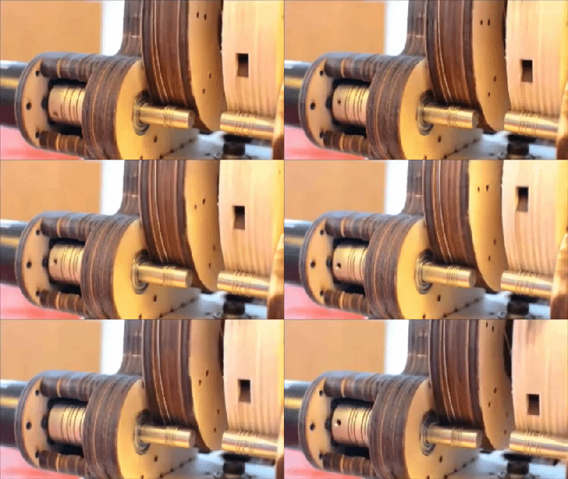
While the Capstan Equation is a huge bummer for preventing us from endlessly weaving our conduit through hard-to-reach sections of our design, a few cases exist where that friction is extremely useful. Since the tension on one side is exponentially related to the tension on the opposite side, with only about four wraps, we can actually use the capstan cylinder to drive the cable directly without worrying about the wire slipping.
This marvelous property gives way to a mechanism called a capstan drive, a cable wrapped around a small shaft that can be used as an actuator. Here, we’ve put the Capstan Equation to work. We’re counting on that exponential relationship so that our cable doesn’t slip while the cylinder is rotated. These mechanisms are just too cool to gloss over, so we’ll revisit them in a future post. Until then, we hope this brief intro helps you think a bit more carefully about routing cables in your next push-pull cable conduit project, tentacles included or not.
When Pong hit the scene in the early 70s, there was something about the simplicity of the 2D monochrome tennis game that made it engaging enough that enthusiastic proto-gamers shorted-out machines by stuffing their coin boxes to overflowing. But even with the simplicity of Pong’s 2D gameplay, the question becomes: could it by made simpler and still be playable?
Surprisingly, if this one-dimensional Pong game is any indication, it actually seems like it can. Where the original Pong made you line up your paddle with the incoming ball, with the main variable being the angle of the carom from your opponent, [mircemk]’s version, limited to a linear game field, makes the ball’s speed the variable. Players take control of the game with a pair of buttons at the far ends of a 60-LED strip of WS2812s. The ball travels back and forth along the strip, bouncing off a player’s paddle only if they push their button at the exact moment the ball arrives. Each reflection back to the opponent occurs at a random speed, making it hard to get into a rhythm. To add some variety, each player has a “Boost” button to put a little spice on their shot, and score is kept by LEDs in the center of the play field. Video of the game play plus build info is below the break.
With just a Neopixel strip, an Arduino Nano, and a small handful of common parts, it should be easy enough to whip up your own copy of this surprisingly engaging game. But if the 2D-version is still more your speed, maybe you should check out the story of its inventor, [Ted Dabney]. Or, perhaps building a clock that plays Pong with itself to idle the days away is more your speed.
Linux users are more likely than most to be familiar with Chromium, Google’s the free and open source web project that serves as the basis for their wildly popular Chrome. Since the project’s inception over a decade ago, users have been able to compile the BSD licensed code into a browser that’s almost the same as the closed-source Chrome. As such, most distributions offer their own package for the browser and some even include it in the base install. Unfortunately, that may be changing soon.
A post made earlier this month to the official Chromium Blog explained that an audit had determined “third-party Chromium based browsers” were using APIs that were intended only for Google’s internal use. In response, any browser attempting to access features such as Chrome Sync with an unofficial API key would be prevented from doing so after March 15th.
To the average Chromium user, this doesn’t sound like much of a problem. In fact, you might even assume it doesn’t apply to you. The language used in the post makes it sound like Google is referring to browsers which are spun off of the Chromium codebase, and at least in part, they are. But the search giant is also using this opportunity to codify their belief that the only official Chromium builds are the ones that they provide themselves. With that simple change, anyone using a distribution-specific build of Chromium just became persona non grata.
Unhappy with the idea of giving users a semi-functional browser, the Chromium maintainers for several distributions such as Arch Linux and Fedora have said they’re considering pulling the package from their respective repositories altogether. With a Google representative confirming the change is coming regardless of community feedback, it seems likely more distributions will follow suit.
Broken Promises
For most users, this is little more than a minor annoyance. Sure it was nice to have Chromium available in your distribution’s package repository, but popping over to the official website and downloading the latest stable is hardly the end of the world. Those running older machines may be in for a rude awaking however, as Google no longer makes 32-bit builds available. They also don’t provide a native BSD build at the time of this writing. For those users, it may be time to give Firefox a shot.
Soon to be a memory of simpler times?
The people that are actually hurt the most by this decision are the ones who’ve spent years packaging Google’s open source browser. They’ve put in considerable time and effort to compile, distribute, and support a custom built Chromium, only to have Google pull the rug out from under them without so much as a call for comments. You might think that’s just one of the risks you take on when supporting a BSD-licensed project, which by definition offers no implied warranty, but in this case things are a little less cut and dry.
As developer Eric Hameleers explains in a lengthy blog post, he was supplied with a dedicated API key for his Slackware Chromium builds by the Google Chrome Team in 2013. He was granted “official permission to include Google API keys in your packages”, and was told that the usage quota for that particular key would be increased “in an effort to adequately support your users”, as normally the key he was assigned would only be for personal development use. Evangelos Foutras, the maintainer for the Arch Linux Chromium package, has indicated he received a similar email at around the same time.
There’s no question that Google understood how these individuals intended to use their API keys. They were even given special dispensation to circumvent API limits, a decision which must have gone through several layers of approvals. The framework for giving distribution-specific Chromium packages the same level of functionality as official builds was agreed upon and put into operation years ago, that much is certain. What’s less clear is what happened internally at Google that prompted them to terminate these existing agreements with little more than a vague blog post to serve as notification.
Keys to the Kingdom
We may never get the full story in this situation, and since a Google representative has made it clear that the decision is final, there’s not much sense fretting over it. Ultimately, Google is going to run their business as they see fit. If they think allowing unofficial builds of Chromium to tap into their cloud services such as Sync isn’t worth it, it’s their prerogative to block them. Those who believe firmly in the concept of free and open source software would tell you that this is a perfect example of why you should have been using Firefox or another truly libre browser in the first place.
On the other hand, hackers as a whole aren’t overly fond of being told what to do. Finding unconventional solutions to arbitrary limitations is the name of the game, so what options exist for those who can’t or won’t use the official Chromium builds from Google? Foutras has put forward an interesting suggestion that, at least on the surface, doesn’t seem to run afoul of Google’s Terms of Service. Though that certainly doesn’t mean they’ll be happy about it.
Put simply, there doesn’t appear to be any technical reason that a third-party build of Chromium couldn’t simply use the official API keys that ship with Chrome. These keys have been publicly known since at least 2012, and in all that time, have never been changed. While actually distributing a build of Chromium using these keys may be enough of a gray area that mainline distributions would steer clear, a separate script that executes on the end-user’s machine and slips the keys into the relevant environment variables may be a loophole Google wasn’t expecting.
If you ever watched Dr. Who, you probably know that the TARDIS looked like a police call box on the outside, but was very large on the inside. When asked, the Doctor had some explanation of how something can look small when it is far away and large when it is close up, which never made much sense. However, [iQLess] has been 3D printing boxes in a small area, that fold out to be much larger boxes. (Video, embedded below.) The design comes from someone called [Cisco] who has a lot of interesting print in place designs.
You can find the design on the Prusa site or Thingiverse. The boxes do take a while to print, according to the video below. What was interesting to us, though, is that you should be able to print a design like this to create a box larger than your printer.
There are two versions of the box, a large one and a small one. The small box took about 10 hours to print with an estimated cost of just over a dollar. The large box takes about 24 hours to print on the machine [iQLess] uses.
Of course, any time you are printing hinges in place, you need your printer well calibrated so you don’t wind up with an immobile blob.
If engineering choices a hundred years ago had been only slightly different, we could have ended up in a world full of steam engines rather than internal combustion engines. For now, though, steam engines are limited to a few niche applications and, of course, models built by enthusiasts. This one for example is built entirely in LEGO as a scale replica of a steam engine originally produced in 1907.
The model is based on a 2500 horsepower triple-expansion four-cylinder engine that was actually in use during the first half of the 20th century. Since the model is built using nothing but LEGO (and a few rubber bands) it operates using a vacuum rather than with working steam, but the principle is essentially the same. It also includes Corliss valves, a technology from c.1850 that used rotating valves and improved steam engine efficiency dramatically for the time.
This build is an impressive recreation of the original machine, and can even run at extremely slow speeds thanks to a working valve on the top, allowing its operation to be viewed in detail. Maximum speed is about 80 rpm, very close to the original machine’s 68 rpm operational speed. If you’d prefer your steam engines to have real-world applications, though, make sure to check out this steam-powered lawnmower.
Now that it is relatively cheap and easy to create a PCB, it is a common occurrence for them to be used in projects. However, there are a lot of subtleties to creating high-performance boards that don’t show up so much on your 555 LED blinker. [Robert Feranec] is well-versed in board layout and he recently highlighted an animation on signal crosstalk with [Eric Bogatin] from Teledyne LeCroy. If you want a good understanding of crosstalk and how to combat it, you’ll want to see [Eric’s] presentation in the video below.
Simplifying matters, the heart of the problem lies in running traces close together so that the magnetic fields from one intersect the other. The math is hairy, but [Eric] talks about simple ways to model the system which may not be exact, but will be close enough for practical designs.
The models use inductors and capacitance to represent different modes of crosstalk, and it’s likely you already know how to deal with those quantities. The video shows some simulations and also suggests methods to control the problem.
Even though the topic is PC boards, some of the same ideas apply to cables. Ethernet cables, for example, have specifications for FEXT for similar reasons.
The Mavic Mini uses I2C to communicate with official packs, making the hack relatively straightforward. [aeropic] built a board nicknamed B0B, which tells the drone what it wants to hear and lets it boot up with unofficial batteries installed. The circuit uses a PIC12F1840 to speak to the drone, including reporting voltage on the cells installed. Notably, it only monitors the whole pack, before dividing the voltage to represent the value of individual cells, but it shouldn’t be a major problem in typical use. Combined with a few 3D printed components to hold everything together, it allows you to build your own cheap pack for the Mavic Mini with little more than a PCB and a few 18650 cells.
It’s always good to see hackers getting out and doing the bread and butter work to get around restrictive factory DRM measures, whether its on music, printer cartridges, or drone batteries. We’ve even seen the scourge appear on litter boxes, too. Video after the break.
Piezo elements have the useful property of being bidirectional; that is they can move when you apply electricity to them, but they can also generate electricity when you move them. [Carl] takes advantage of this fact to make buttons that can provide haptic feedback. You can see a video of his efforts below the break.
He made two versions of the buttons. One uses a 3D printed housing and the other used a 3D printed spacer in a sandwich configuration. It took a few tries to get it right, as you’ll see. The elements take and produce relatively high voltages, so the bulk of the work was adapting the voltages back and forth. In fact, he even managed to fry his CPU chip with some of the higher voltages involved.
We’d probably look for an easier way to sense the button push, since it seems like a good bit of circuitry just to do that. But the whole circuit provides an input button, haptic feedback, and the option of using the buzzer as a buzzer, so at least it is relatively economical if you need all of those features.
The last time we saw a piezo speaker detecting something it was looking for knocks on a door. If you want to know more about how transducers like this work, you’ll enjoy this video.
Every nation has icons of national pride: a sports star, a space mission, or a piece of architecture. Usually they encapsulate a country’s spirit, so citizens can look up from their dreary lives and say “Now there‘s something I can take pride in!” Concorde, the supersonic airliner beloved by the late 20th century elite for their Atlantic crossings, was a genuine bona-fide British engineering icon.
But this icon is unique as symbols of national pride go, because we share it with the French. For every British Airways Concorde that plied the Atlantic from London, there was another doing the same from Paris, and for every British designed or built Concorde component there was another with a French pedigree. This unexpected international collaboration gave us the world’s most successful supersonic airliner, and given the political manoeuverings that surrounded its gestation, the fact that it made it to the skies at all is something of a minor miracle.
A Bright Future Of Supersonic Travel
Boeing’s Dash 80 prototype sets the template for today’s jet airliners. Boeing Dreamscape, Public domain
In the 1950s, the direction of post-war aviation had been set by the first generation of four-engined jet passenger aircraft. Planes such as the De Haviland Comet, Tupolev TU-104, Sud Aviation Caravelle, and Boeing Dash-80 prototype are the visible ancestors of today’s airliners, but just as the future of jet fighter aircraft lay in supersonic designs it was envisaged that so too would the future of civil aviation.
By the 1980s, we would zip around the world at twice the speed of sound, and naturally the aircraft manufacturers of the day wanted a slice of that market. Governments and major manufacturers worldwide set their designers researching the feasibility of transforming design elements created for supersonic military aircraft into civilian airliners. By the end of the 1950s the French Sud Aviation and British BAC had advanced to the point of in 1960 investigating a joint venture, and were surprised to find that each other’s designs had arrived at a substantially similar shape and configuration.
A common design was agreed, and the respective governments contemplated a formal treaty. At this time, the British government was being blocked by the French from European Community membership, and was seeking anything that would sweeten their eventual membership. They thus pushed for a deal, and inserted punitive clauses for breaking it in the resulting 1962 treaty. The aircraft would be built as a cooperative effort between the two countries, with both governments funding the development in the expectation that they could get a head start over the Americans in equipping the airlines of the 1970s.
The Battle Of The Extra “E”
The aircraft that emerged had the familiar thin fuselage and long curved delta wing, and had four Rolls-Royce Olympus 593 turbojet engines derived from those used on the Avro Vulcan bomber mounted under the wings. For use at supersonic speeds, these engines had special intake ducts designed to slow the air down to subsonic speeds. And although they were fitted with afterburners for the climb to cruising altitude, these intakes gave the Concorde the ability to “supercruise”, or cruise at mach 2 supersonic speeds without afterburners engaged.
One of the prototype Concorde aircraft complete with “e” is in the Imperial War Museum, Duxford. Ronnie Macdonald from Chelmsford, United Kingdom, CC BY 2.0
It is inevitable that such a project, at the edge of what is possible, will incur significant overruns. The Concorde was no exception. The first estimate of £70 million soared to a billion and beyond. That the project survived at all was due only to the expense of pulling out due to that punitive clause.
The sometimes testy relationship between the two countries’ political leadership was reflected in its name, variously being referred to with the French spelling of “Concorde” or the English “Concord”. The version with an “e” was finally adopted.
The two prototype aircraft made their maiden flights in 1969, with the French Concorde in Toulouse being the first. These two planes flew into a different environment from that envisaged in the 1950s. Concerns about noise and pollution, as well as the Oil Crisis in the early 1970s, led to much of the interest of the airlines in supersonic luxury travel melting away, and by the time the first production aircraft were under way only the two national airlines remained. The two governments were left having spent eye-watering sums to produce only a few aircraft, and opted to swallow the loss by passing them to the airlines. They were sold to the public as that source of national pride, and to this day that is how they are seen rather than as a colossal sinkhole of public money.
The Unthinkable Happens
The memorial to those killed in the Concorde crash, Gonesse, France. Marbus1966, CC BY-SA 4.0
Concorde’s use for special charter flights meant that it would often fly over parts of the UK outside of its normal scheduled routes, and even when it was a couple of decades old it would cause people to stop and watch it go by. “National icon” is a phrase that is sometimes used inappropriately, but for Brits and presumably the French too, it definitely applied to Concorde during those decades. It seemed to be a fixture without an end to its service.
But in July 2000, the aircraft suffered its first and only fatal crash. An Air France charter flight hit a piece of runway debris at Paris Charles de Gaulle airport, causing a fuel tank failure and fire that led to the aircraft crashing with the loss of all on board after only two minutes of flight.
The fleet was grounded while investigations were carried out and all aircraft were fitted with fuel tank modifications, but their return to the air was short-lived. In 2003 the entire fleet was retired by both airlines, causing a brief controversy. Civilian supersonic airline flight had not become travel for the masses as was once predicted, and while still a source of national pride, the aircraft had become something of an anachronism. Meanwhile we’re left to queue for our twin-engined subsonic widebody aircraft flights, and hope that one day Reaction Engines might rekindle the dream.
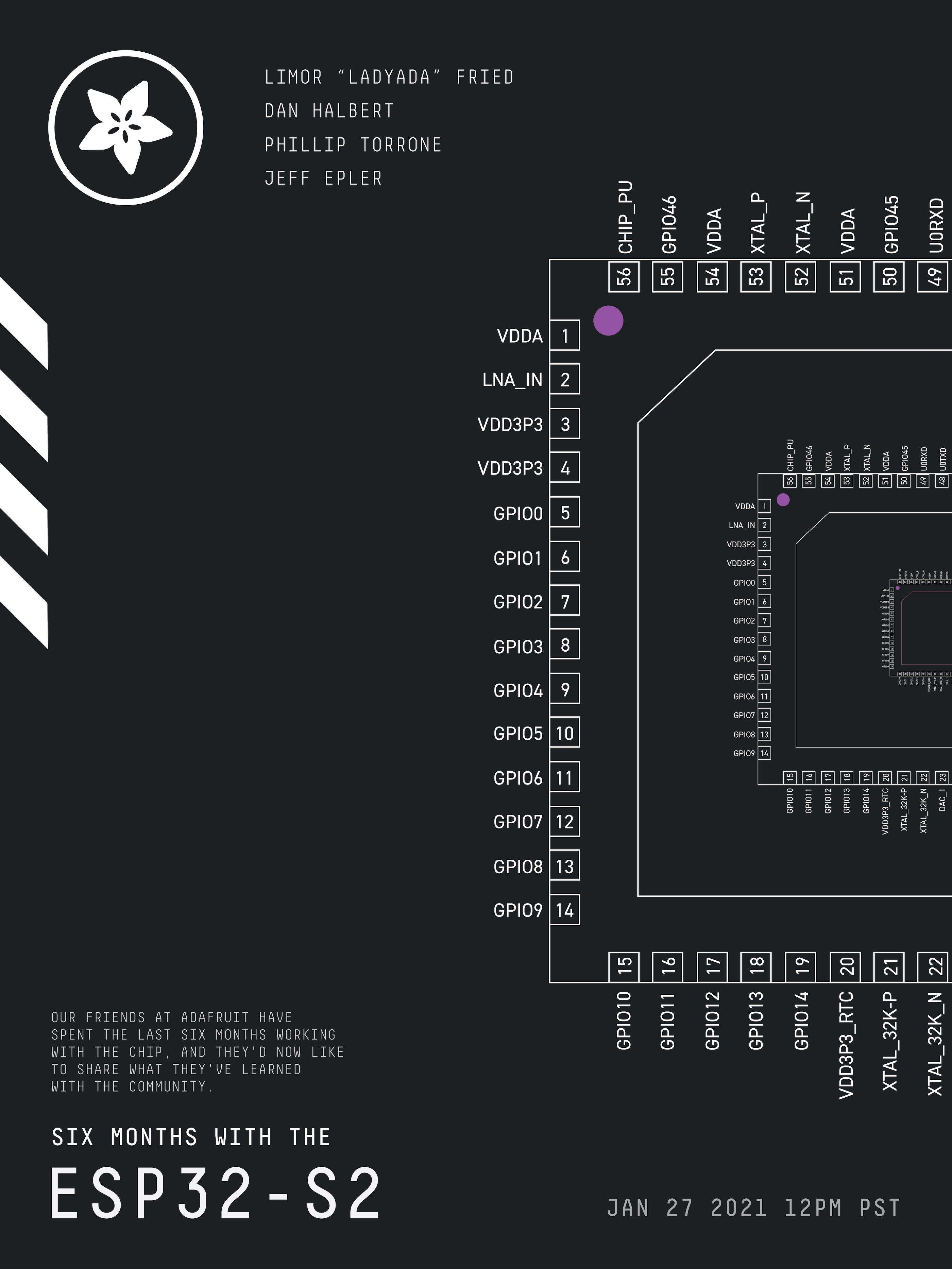
It’s always an event when we have Adafruit on the Hack Chat, and last time was no exception. Then, the ESP32-S2 was the new newness, and Adafruit was just diving into what’s possible with the chip. It’s an interesting beast — with a single core and no Bluetooth or Ethernet built-in, it appears to be less capable than other Espressif chips. But with a faster CPU, more GPIO and ADCs, a RISC-V co-processor, and native USB, the chip looked promising.
Among their other duties, the folks at Adafruit have spent the last six months working with the chip, and they’d now like to share what they’ve learned with the community. So Limor “Ladyada” Fried, Phillip Torrone, Scott Shawcroft, Dan Halbert, and Jeff Epler will stop by the Hack Chat to show us what’s under the hood of the ESP32-S2. They’ve worked on a bunch of projects using the chip, and they’ve taken a deep-dive into the chip’s deep-sleep capabilities, so stop by the Chat with your burning questions about low-power applications or anything ESP32-S2-related and ask away.
Plus, a late and exciting addition to the agenda: they’ll be talking about the recently released RP2040, the first custom chip from the folks at Raspberry Pi. We’ve already started talking about the Raspberry Pi Pico, the dev board that uses the chip, and Adafruit will share what they’ve learned about the RP2040 so far.
Click that speech bubble to the right, and you’ll be taken directly to the Hack Chat group on Hackaday.io. You don’t have to wait until Wednesday; join whenever you want and you can see what the community is talking about.
It’s always an event when we have Adafruit on the Hack Chat, and last time was no exception. Then, the ESP32-S2 was the new newness, and Adafruit was just diving into what’s possible with the chip. It’s an interesting beast — with a single core and no Bluetooth or Ethernet built-in, it appears to be less capable than other Espressif chips. But with a faster CPU, more GPIO and ADCs, a RISC-V co-processor, and native USB, the chip looked promising.
Among their other duties, the folks at Adafruit have spent the last six months working with the chip, and they’d now like to share what they’ve learned with the community. So Limor “Ladyada” Fried, Phillip Torrone, Scott Shawcroft, Dan Halbert, and Jeff Epler will stop by the Hack Chat to show us what’s under the hood of the ESP32-S2. They’ve worked on a bunch of projects using the chip, and they’ve taken a deep-dive into the chip’s deep-sleep capabilities, so stop by the Chat with your burning questions about low-power applications or anything ESP32-S2-related and ask away.
Plus, a late and exciting addition to the agenda: they’ll be talking about the recently released RP2040, the first custom chip from the folks at Raspberry Pi. We’ve already started talking about the Raspberry Pi Pico, the dev board that uses the chip, and Adafruit will share what they’ve learned about the RP2040 so far.
Click that speech bubble to the right, and you’ll be taken directly to the Hack Chat group on Hackaday.io. You don’t have to wait until Wednesday; join whenever you want and you can see what the community is talking about.
It’s always an event when we have Adafruit on the Hack Chat, and last time was no exception. Then, the ESP32-S2 was the new newness, and Adafruit was just diving into what’s possible with the chip. It’s an interesting beast — with a single core and no Bluetooth or Ethernet built-in, it appears to be less capable than other Espressif chips. But with a faster CPU, more GPIO and ADCs, a RISC-V co-processor, and native USB, the chip looked promising.
Among their other duties, the folks at Adafruit have spent the last six months working with the chip, and they’d now like to share what they’ve learned with the community. So Limor “Ladyada” Fried, Phillip Torrone, Scott Shawcroft, Dan Halbert, and Jeff Epler will stop by the Hack Chat to show us what’s under the hood of the ESP32-S2. They’ve worked on a bunch of projects using the chip, and they’ve taken a deep-dive into the chip’s deep-sleep capabilities, so stop by the Chat with your burning questions about low-power applications or anything ESP32-S2-related and ask away.
Plus, a late and exciting addition to the agenda: they’ll be talking about the recently released RP2040, the first custom chip from the folks at Raspberry Pi. We’ve already started talking about the Raspberry Pi Pico, the dev board that uses the chip, and Adafruit will share what they’ve learned about the RP2040 so far.
Click that speech bubble to the right, and you’ll be taken directly to the Hack Chat group on Hackaday.io. You don’t have to wait until Wednesday; join whenever you want and you can see what the community is talking about.
Sure it is a cheap stage trick, but using a lenticular lens at the right angle and in front of the right background can render what’s behind it invisible. That’s not news, but [Ian] spent some time investigating how to make the best one he could. His instructions cover how to create your own with polycarbonate, the right lens, and some optically clear adhesive. You can see some details about the shield along with some demonstrations in the video below.
The first iteration of the design worked, but it had some distracting lines and curvatures. The second version uses a large sheet of polycarbonate and liquid adhesive to attach the lens. It looks much better.
The effect works best when you have a bold horizontal pattern behind you and, of course, only works from certain sight angles. Even then, you can see when [Ian] is moving behind the shield, but it is pretty muted. However, the final version did look better even though UV curing that big sheet of plastic looked painful.
The final few minutes of the video shows some real world user testing that looked like a lot of fun. There are other ways to bend light to get limited invisibility. We’ve seen these lenses used for faux holograms, too.
The January 16th “Green Run” test of NASA’s Space Launch System (SLS) was intended to be the final milestone before the super heavy-lift booster would be moved to Cape Canaveral ahead of its inaugural Artemis I mission in November 2021. The full duration static fire test was designed to simulate a typical launch, with the rocket’s main engines burning for approximately eight minutes at maximum power. But despite a thunderous start start, the vehicle’s onboard systems triggered an automatic abort after just 67 seconds; making it the latest in a long line of disappointments surrounding the controversial booster.
When it was proposed in 2011, the SLS seemed so simple. Rather than spending the time and money required to develop a completely new rocket, the super heavy-lift booster would be based on lightly modified versions of Space Shuttle components. All engineers had to do was attach four of the Orbiter’s RS-25 engines to the bottom of an enlarged External Tank and strap on a pair of similarly elongated Solid Rocket Boosters. In place of the complex winged Orbiter, crew and cargo would ride atop the rocket using an upper stage and capsule not unlike what was used in the Apollo program.
The SLS core stage is rolled out for testing.
There’s very little that could be called “easy” when it comes to spaceflight, but the SLS was certainly designed to take the path of least resistance. By using flight-proven components assembled in existing production facilities, NASA estimated that the first SLS could be ready for a test flight in 2016.
If everything went according to schedule, the agency expected it would be ready to send astronauts beyond low Earth orbit by the early 2020s. Just in time to meet the aspirational goals laid out by President Obama in a 2010 speech at Kennedy Space Center, including the crewed exploitation of a nearby asteroid by 2025 and a potential mission to Mars in the 2030s.
But of course, none of that ever happened. By the time SLS was expected to make its first flight in 2016, with nearly $10 billion already spent on the program, only a few structural test articles had actually been assembled. Each year NASA pushed back the date for the booster’s first shakedown flight, as the project sailed past deadlines in 2017, 2018, 2019, and 2020. After the recent engine test ended before engineers were able to collect the data necessary to ensure the vehicle could safely perform a full-duration burn, outgoing NASA Administrator Jim Bridenstine said it was too early to tell if the booster would still fly this year.
What went wrong? As commercial entities like SpaceX and Blue Origin move in leaps and bounds, NASA seems stuck in the past. How did such a comparatively simple project get so far behind schedule and over budget?
The Rocket to Nowhere
Arguably, the most pressing problem with the SLS program is that it has no clear purpose. As a congressionally mandated project, NASA must continue on with its development regardless of whether or not they actually have a use for it. Critics have often referred to the program as the “Senate Launch System”, as they believe the Shuttle-derived concept was conceived primarily as a way to make sure the manufacturing facilities used to build the engines, propellant tanks, and solid rocket boosters for the Space Shuttle would remain in operation even after the program was retired.
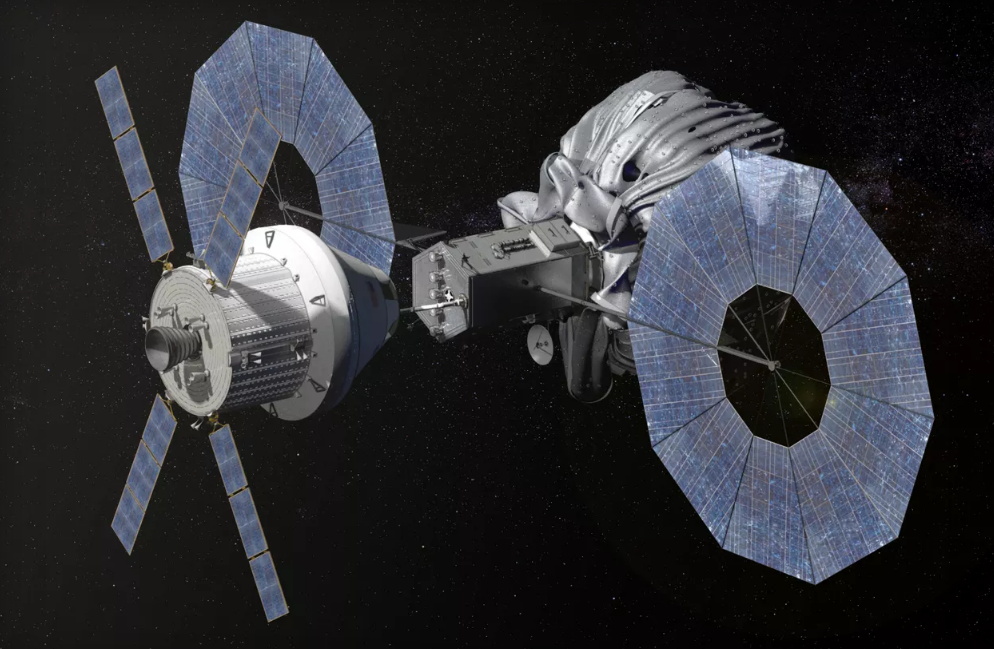
The deep space asteroid mission was canceled in 2017.
Without a clear mission for the SLS, it’s been difficult for NASA engineers to make any long-term development plans. What payload does the booster need to carry, and to where, are key questions that need to be answered. NASA is no longer pursuing the mission to recover a near Earth asteroid, and a human mission to Mars is still decades away. The SLS is scheduled to launch the Europa Clipper to Jupiter in 2025, though the Falcon Heavy is already being considered as a backup should it not be ready in time.
While its ultimate effectiveness is debatable, the design of the Space Shuttle was driven by a very specific goal: to transport large objects to and from low Earth orbit inside of its cargo bay. Every decision made during the program’s lifetime revolved around that core tenet. Without similar guidance, the Space Launch System has found itself adrift.
Put simply, the single defining characteristic of the SLS is the sheer mass it’s capable of putting into space. The rocket’s base Block I configuration is designed to put 95,000 kg (209,000 lb) into low Earth orbit, and the later Block II version 130,000 kg (290,000 lb). But while these are impressive figures, it’s not immediately clear what type of mission architecture would require such massive modules to be launched in a single-shot. The 50 years of experience gained since the Apollo era has taught us that modular systems, launched on competitively priced boosters and assembled in orbit, is the key to creating a sustainable space infrastructure.
Squandered Reusability
From the beginning, the Space Shuttle was designed to be an almost completely reusable architecture. Aside from the External Tank, every component of the system could be recovered, refurbished, and flown again. The idea being that it would be cheaper and faster to reuse the same vehicle than it would be to build a new one for each mission.
Unfortunately the complexity and cost of the refurbishment process was greatly underestimated, due in part to technical and material limitations of the era. In the end, the Shuttle never launched as affordably and as rapidly as its designers had hoped, but the lessons learned during the program helped shape modern reusable spacecraft such as Sierra Nevada Corporation’s Dream Chaser and the Boeing X-37B.
But despite the current trend towards reusable rockets and spacecraft, NASA is taking a step backwards with the SLS by using components which were designed for refurbishment and discarding them the end of each flight. The RS-25 engines installed on the first SLS rocket are not newly manufactured, they are literally the same engines that were pulled from the Shuttle Orbiters when they were put into museums. The same is true with the Solid Rocket Boosters (SRBs); the new elongated boosters are using segments from the Shuttle’s original SRBs, but instead of coming down on parachutes to be recovered, they will smash into the ocean and sink.
Each flight of the SLS will destroy four Shuttle-era RS-25 engines and two SRBs, simply because they were taking up space in a NASA warehouse. From a historical standpoint, this is abhorrent. But more practically speaking, integrating these decades-old components into a modern launcher has proven to be far more difficult than anticipated. While they’ve seen some upgrades since the retirement of the Shuttle, it’s no exaggeration to say that some of the people working on the SLS today were not born when its engines were built.
As of right now, NASA only has enough RS-25 engines leftover from the Shuttle program to support four SLS flights. To address this, the agency has already contracted Aerojet Rocketdyne to produce a new version of the engine called the RS-25E that’s designed to be expendable. Unfortunately, these design changes come at a steep price. Each RS-25E will cost NASA nearly $150 million, which is more than what SpaceX charges for a flight on the Falcon Heavy. With a per-launch price that will easily exceed that of the infamously expensive Space Shuttle, it’s difficult to imagine how SLS can possibly remain competitive with reusable commercial vehicles set to begin operation within the current decade such as SpaceX’s Starship and Blue Origin’s New Glenn.
A Calculated Risk
After examining the data, NASA says the automated abort during the January 16th engine test was due to intentionally conservative test limits intended to avoid unnecessary stress on the booster. In a press conference, Administrator Bridenstine said that had this been a real flight, the engines would have remained firing for the full duration necessary to reach orbit. He went on to explain that there is an inherent risk involved should NASA or prime contractor Boeing decide to rerun the full duration test fire, as the propellant tanks can only be filled and drained a finite number of times.
Orion heading to the Moon during Artemis I
While nothing has been determined yet, these statements would seem to indicate that NASA may decide not to repeat the test fire and push ahead with the Artemis I mission to ensure they make the current November 2021 launch date. Conventional wisdom would say this is unwise, but as the first flight won’t have any human occupants, the usually risk-averse space agency might be willing to roll the dice if it means they can avoid another costly delay on a program that’s already facing fierce criticism.
On the other hand, live streaming the explosion of their first Space Launch System rocket to millions of viewers all over the world is hardly going to improve matters. A catastrophic failure during Artemis I would also very likely result in a delay to the crewed Artemis II that’s tentatively scheduled for August 2023. The resulting domino effect would likely make it all but impossible that NASA could make the already ambitious deadline for putting the first woman and next man on the lunar surface by 2024.







 Now let’s start by putting both sides in tension with two tension values: TLoad and THold. We’ll keep the tension constant on THold, but let’s slowly increase value of TLoad. If our cylinder were actually frictionless pulley, trying to create a mismatch in tension would be impossible; the tension on one side would always be equal to the tension on the other side. But because our cylinder is fixed, it is, in fact, possible to increase the tension on one side while keeping the tension on the other side constant, all while the rope doesn’t slip in the process. This happens because static friction on the cylinder is acting against the tension increase up to a certain limit.