Controlling blinds using off the shelf solutions can be expensive – more so if you have multiple blinds you want to control. [HumanSkunk87] felt the cost was too high, so they designed a controller to automatically open and close the blinds.
The main part of this build is a motor and a ball chain gear – a wheel that captures the balls of a ball chain so that the chain can be pulled. The wheel was designed using Fusion3D and then printed out. The motor requires enough power to pull the chain — [HumanSkunk87] figures it needs to be able to pull about 2.5kg in order to raise the blind. After giving up on stepper motors, a DC motor with a worm gear was found to have enough torque to work. A WEMOS D1 Mini controls the motor controller that drives the ball chain wheel. Two micro switches tell the WEMOS when to stop at the bottom and top of the window.
The WEMOS is programmed using ESPHome and it connects to [HumanSkunk87]’s HomeAssistant to complete the automation. Check out the descriptions in the link for the parts and the code used to run everything. There are many other creative ways to open your blinds, It’s even possible to automate curtains instead of blinds.
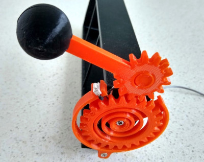
For some reason, when slot machines went digital, they lost their best feature — the handle. Who wants to push a button on a slot machine, anyway? Might as well just play video poker. [John Bradnam] seems to agree, and has built an open-source three-color matrix slot machine complete with handle.
In this case, you’ll be losing all of your nickels to an Arduino Pro Mini. The handle is an upgrade to an earlier slot machine project that uses three 8×8 matrices and a custom driver board. When the spring-loaded handle is pulled, it strikes a micro switch to spins the reels and then snaps back into place. Between each pull, the current score is displayed across the matrix. There’s even a piezo buzzer for victory squawks. We only wish the button under the handle were of the clickier variety, just for the feels. Check out the short demo video after the break.
[Ben’s] build goes above and beyond the usual craft project masks. It uses a laser-cut chipboard frame to fit three HEPA filters, originally designed for the Roomba robotic vacuum cleaner. Two are used for exhalation, while one is used for inhalation. A small blower fan is installed with the intake filter, to provide mild positive pressure when breathing in. The assembly is wrapped up in fabric, using layers of spandex, fleece, and ripstop nylon to provide the best possible seal against the wearer’s face.
It’s a build that should appeal to those who want to breathe cleaner air and also protect others from exhaled particles that can spread respiratory viruses. We’ve seen all kind of masks hit the scene this year; the graphene-impregnated variety is one of the more interesting designs. Still, one can hope that future years lead to less reliance on such measures!
In 2020 when we carry an all-purpose computer and data terminal able to store our every thought and deed on a global computer network, it’s easy to forget that once upon a time we were excited by the simpler things. Take the camcorder for example, back in the 1990s the idea of a complete video recording solution that captured moving images on tape cartridges and fit in the palm of your hand was a very big deal indeed, and camcorders as we called them in those innocent times were a prized posession. Now they’re a $0.50 find a Goodwill, which is how [Dustin] picked up the RCA camcoder he’s converting into something altogether more modern. He’s gutted it and upgraded it by removing the analogue innards and retaining only the case and lens assembly to put around a Raspberry Pi and associated HQ camera module.
Opening the camcorder up reveals a ton of miniaturised analogue circuitry, but once the original assemblies are removed it’s relatively straightforward to put the Pi camera on the rear of the lens unit. There’s plenty of space for the Pi in the box, and he’s putting a touchscreen on the outside.
Sadly the camcorder’s original tiny CRT is no longer working, else that would have been the ultimate retro viewfinder. Still we hope to see some tinkering on that part of the project since those little CRTS make for delightful hacks. The project is very much a work in progress, but should serve that these once ubiquitous devices are now in the realm of the throwaway.
Imagine that you’re serving on a jury, and you’re given an image taken from a surveillance camera. It looks pretty much like the suspect, but the image has been “enhanced” by an AI from the original. Do you convict? How does this weigh out on the scales of reasonable doubt? Should you demand to see the original?
AI-enhanced, upscaled, or otherwise modified images are tremendously realistic. But what they’re showing you isn’t reality. When we wrote about this last week, [Denis Shiryaev], one of the authors of one of the methods we highlighted, weighed in the comments to point out that these modifications aren’t “restorations” of the original. While they might add incredibly fine detail, for instance, they don’t recreate or restore reality. The neural net creates its own reality, out of millions and millions of faces that it’s learned.
And for the purposes of identification, that’s exactly the problem: the facial features of millions of other people have been used to increase the resolution. Can you identify the person in the pixelized image? Can you identify that same person in the resulting up-sampling? If the question put before the jury was “is the defendant a former president of the USA?” you’d answer the question differently depending on which image you were presented. And you’d have a misleading level of confidence in your ability to judge the AI-retouched photo. Clearly, informed skepticism on the part of the jury is required.
Unfortunately, we’ve all seen countless examples of “zoom, enhance” in movies and TV shows being successfully used to nab the perps and nail their convictions. We haven’t seen nearly as much detailed analysis of how adversarial neural networks create faces out of a scant handful of pixels. This, combined with the almost magical resolution of the end product, would certainly sway a jury of normal folks. On the other hand, the popularity of intentionally misleading “deep fakes” might help educate the public to the dangers of believing what they see when AI is involved.
This is just one example, but keeping the public interested in and educated on the deep workings and limitations of the technology that’s running our world is more important than ever before, but some of the material is truly hard. How do we separate the science from the magic?
This article is part of the Hackaday.com newsletter, delivered every seven days for each of the last 200+ weeks. It also includes our favorite articles from the last seven days that you can see on the web version of the newsletter.
Want this type of article to hit your inbox every Friday morning? You should sign up!
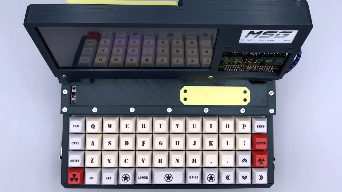
Over the last couple of years the cyberdeck community has absolutely exploded. Among those who design and build these truly personal computers there are no hard rules, save perhaps making sure the final result looks as unconventional as possible. But one thing that’s remained fairly consistent is the fact that these machines are almost exclusively powered by the Raspberry Pi. Unfortunately, that means they often leave something to be desired in terms of raw performance.
But [MSG] had a different idea. His cyberdeck still has the customary Raspberry Pi inside, but it also has an i7 Intel NUC that can be fired up at the touch of a button. He says it’s the best of both worlds: an energy efficient ARM Linux platform for mobile experimentation, and a powerful x86 Windows box for playing games working from home. It’s the hacker equivalent of business in the front, party in the back.
With a KVM connected to the custom Planck 40% mechanical keyboard and seven inch LCD, [MSG] can switch between both systems on the fly. Assuming he’s got the juice anyway; while the Raspberry Pi 4 and LCD is able to run on a pair of 18650 batteries, the cyberdeck needs to be plugged in if he wants to use the power-hungry NUC. If he ditched the Pi he could potentially load up the case with enough batteries to get the Intel box spun up, but that would be getting a little too close to a conventional laptop.
The whole plurality theme doesn’t stop at the computing devices, either. In addition to the primary LCD, there’s also a 2.13 inch e-paper display and a retro-style LED matrix courtesy of a Pimoroni Micro Dot pHAT. With a little Python magic behind the scenes, [MSG] is able to display things like the system temperature, time, and battery percentage even when the LCD is powered down.
Building radio receivers from scratch is still a popular project since it can be done largely with off-the-shelf discrete components and a wire long enough for the bands that the radio will receive. That’s good enough for AM radio, anyway, but you’ll need to try this DIY FM receiver if you want to listen to something more culturally relevant.
Receiving frequency-modulated radio waves is typically more difficult than their amplitude-modulated cousins because the circuitry necessary to demodulate an FM signal needs a frequency-to-voltage conversion that isn’t necessary with AM. For this build, [hesam.moshiri] uses a TEA5767 FM chip because of its ability to communicate over I2C. He also integrated a 3W amplifier into this build, and everything is controlled by an Arduino including a small LCD screen which displays the current tuned frequency. With the addition of a small 5V power supply, it’s a tidy and compact build as well.
While the FM receiver in this project wasn’t built from scratch like some AM receivers we’ve seen, it’s still an interesting build because of the small size, I2C capability, and also because all of the circuit schematics are available for all of the components in the build. For those reasons, it could be a great gateway project into more complex FM builds.
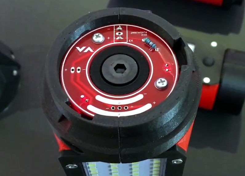
While it does use the same M12 batteries, this impeccably engineered work light isn’t an official Milwaukee product. It’s the latest creation from [Chris Chimienti], who’s spent enough time in the garage and under the hood to know a thing or two about what makes a good work light. The modular design not only allows you to add or subtract LED panels as needed, but each section is able to rotate independently so it points exactly where you need it.
Magnets embedded in the 3D printed parts mean the light modules not only firmly attach to one another, but can be stuck to whatever you’re working on. Or you could just stack all the lights up vertically and use the rocket-inspired “landing legs” of the base module keep it vertical. Even if the light gets knocked around, the tension provided by rubber bands attached to each fold-out leg means it will resist falling over. In the video after the break [Chris] says the little nosecone on top is just for fun and you don’t have to print it, but we don’t see how you can possibly resist.
The same PCB is used on both ends of the light modules.
Of course, 3D printed parts and magnets don’t self-illuminate. The LED panels and switches are salvaged from cheap lights that [Chris] found locally for a few bucks, and a common voltage regulator board is used to step the 12 volts coming from the Milwaukee battery down to something the LEDs can use. He’s designed a very slick reversible PCB that’s used on either end of each light module to transfer power between them courtesy of semi-circular traces on one side and and matching pogo pins on the other.
As we saw in his recent Dremel 3D20 rebuild, [Chris] isn’t afraid to go all in during the design phase. The amount of CAD work that went into this project is astounding, and serves as fantastic example of the benefits to be had by designing the whole assembly at once rather than doing it piecemeal. It might take longer early on, but the final results really speak for themselves.
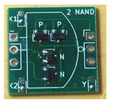
What do you get when you stick 1738 MOSFETs together? If your answer was a ‘4-bit CPU’, you would be totally correct. Available as a product over at Marutsu as the ‘CPU1738’, it seems to target beginners to computer theory, with build instructions that explain how the CPU is built up from individual MOSFETs that are combined into logic gates.
A CPU1738 NAND PCB.
While decidedly more compact in its SMD format than it would have been with pure through-hole parts, the use of countless small PCBs on top of the larger PCBs make for a pretty hefty package. Board after board build up the CPU, and the assembly continues with the addition of sensors, motors, and wheels. In the end, a robot emerges, albeit a somewhat wobbly-looking one.
Check out the video linked after the break, though before starting one up, note the 50,000 Yen (approximately $500) price tag for the CPU block alone. On the other hand, in addition to the 1738 MOSFETs, there are also 1070 LEDs, so you get what you pay for in blinkies.
What do you get when you stick 1738 MOSFETs together? If your answer was a ‘4-bit CPU’, you would be totally correct. Available as a product over at Marutsu as the ‘CPU1738’, it seems to target beginners to computer theory, with build instructions that explain how the CPU is built up from individual MOSFETs that are combined into logic gates.
A CPU1738 NAND PCB.
While decidedly more compact in its SMD format than it would have been with pure through-hole parts, the use of countless small PCBs on top of the larger PCBs make for a pretty hefty package. Board after board build up the CPU, and the assembly continues with the addition of sensors, motors, and wheels. In the end, a robot emerges, albeit a somewhat wobbly-looking one.
Check out the video linked after the break, though before starting one up, note the 50,000 Yen (approximately $500) price tag for the CPU block alone. On the other hand, in addition to the 1738 MOSFETs, there are also 1070 LEDs, so you get what you pay for in blinkies.
What do you get when you stick 1738 MOSFETs together? If your answer was a ‘4-bit CPU’, you would be totally correct. Available as a product over at Marutsu as the ‘CPU1738’, it seems to target beginners to computer theory, with build instructions that explain how the CPU is built up from individual MOSFETs that are combined into logic gates.
A CPU1738 NAND PCB.
While decidedly more compact in its SMD format than it would have been with pure through-hole parts, the use of countless small PCBs on top of the larger PCBs make for a pretty hefty package. Board after board build up the CPU, and the assembly continues with the addition of sensors, motors, and wheels. In the end, a robot emerges, albeit a somewhat wobbly-looking one.
Check out the video linked after the break, though before starting one up, note the 50,000 Yen (approximately $500) price tag for the CPU block alone. On the other hand, in addition to the 1738 MOSFETs, there are also 1070 LEDs, so you get what you pay for in blinkies.
There are a lot of keyboards to choose from, and a quick trip through some of the forums will quickly show you how fanatical some people can be about very specific styles or switches. [Crdotson] doesn’t seem to be too far down the rabbit hole in that regard, but he does have a keyboard that he really likes despite one small quirk: it’s built for Mac, and some of the modifier keys aren’t laid out correctly for Windows. Since Windows has limited (and poor) options for software keymapping, he took an alternative route and built a keymapper in hardware instead.
The build uses a Raspberry Pi as a go-between from the keyboard to his computer. The Pi watches the USB bus using usbmon, which allows inspection of the packets and can see which keys have been pressed. It then passes those keypresses through to the computer. His only modification to the keyboard mapping is to swap the Alt and Super (Windows) keys for his keyboard of choice, although using this software would allow any other changes to be made as well. Latency is only on the order of a few microseconds, which is not noticeable for normal use cases.
While we have seen plenty of other builds around that can map keyboards in plenty of custom ways, if you don’t have the required hardware for a bespoke solution it’s much more likely that there’s a Raspberry Pi laying around that can do the job instead. There are a few issues with the build that [crdotson] is planning to tackle, though, such as unplugging the device while a key is being pressed, which perpetually sends that keystroke to the computer without stopping. But for now it’s a workable solution for his problem.
An anonymous reader pinged us about an issue that affects people who jumped onto the latest-and-greatest OS from the Apple gardens: USB devices that stop working due to the FTDI-based USB solution. At its core appears to be that the built-in FTDI driver provided by Apple (AppleUSBFTDI.dext) only supports FTDI chips which provide the standard FTDI vendor and product ID (e.g. 0x0403 and 0x6001 respectively for the FT232R). Many products however set a custom product ID (PID) to differentiate their device, though in the thread some mention that there are driver issues even with the default VID/PID combination.
Over the past years, Apple has been restricting and changing the way kernel extensions (KExt) and driver extensions (DExt) are handled. As these FTDI chips are often used for virtual com port (VCP) purposes, such as with Arduino boards and USB-TTL adapters, this is a rather cumbersome issue that would affect anyone using Big Sur in combination with such a hardware device.
So far only the FTDI team has been somewhat responsive based on the support forum thread, with Apple seemingly rather silent on the issue.
Today the National Science Foundation released a pair of videos that document the collapse of the Arecibo Observatory with incredible detail. A wide shot, apparently taken from the Visitors Center, shows the 900 ton instrument platform breaking free and swinging on the remaining support cables until it smashes into the edge of the dish. The second clip, recorded by an airborne drone, is focused directly on the cables as they failed. Both can be seen in the video embedded below.
Together, they produce an invaluable visual record of what finally brought the iconic radio telescope down. As was predicted by engineers earlier in the month, the failure of another support cable on tower 4 triggered a chain reaction that brought the entire platform crashing down onto the 305 meter reflector. Footage from a drone observing the top of tower 4 shows that the entire sequence, from the first visual wire break to the remaining cables being torn from their mounts, only took five seconds. While some initially doubted the NSF’s determination that it was too dangerous to repair Arecibo, this footage seems to prove just how tenuous the structural integrity of the Observatory really was.
A drone captured the critical cable failure.
These videos will hopefully help investigators who still need to determine why the cables failed in the first place. The cable in August didn’t snap, it simply pulled lose from its mount. It was suspected that the cable may have been incorrectly installed, but as it was only a backup, the situation was not seen as critical. But when the second cable failed in November it was found to have snapped at just 60% of its minimum breaking strength.
This immediately called into question the condition of the remaining cables, and ultimately lead to the decision by the NSF to proceed with a controlled demolition of the Observatory that would preserve as much of the scientific equipment as possible. Unfortunately, the remaining cables didn’t last long enough to put that plan into action.
Today the National Science Foundation released a pair of videos that document the collapse of the Arecibo Observatory with incredible detail. A wide shot, apparently taken from the Visitors Center, shows the 900 ton instrument platform breaking free and swinging on the remaining support cables until it smashes into the edge of the dish. The second clip, recorded by an airborne drone, is focused directly on the cables as they failed. Both can be seen in the video embedded below.
Together, they produce an invaluable visual record of what finally brought the iconic radio telescope down. As was predicted by engineers earlier in the month, the failure of another support cable on tower 4 triggered a chain reaction that brought the entire platform crashing down onto the 305 meter reflector. Footage from a drone observing the top of tower 4 shows that the entire sequence, from the first visual wire break to the remaining cables being torn from their mounts, only took five seconds. While some initially doubted the NSF’s determination that it was too dangerous to repair Arecibo, this footage seems to prove just how tenuous the structural integrity of the Observatory really was.
A drone captured the critical cable failure.
These videos will hopefully help investigators who still need to determine why the cables failed in the first place. The cable in August didn’t snap, it simply pulled lose from its mount. It was suspected that the cable may have been incorrectly installed, but as it was only a backup, the situation was not seen as critical. But when the second cable failed in November it was found to have snapped at just 60% of its minimum breaking strength.
This immediately called into question the condition of the remaining cables, and ultimately lead to the decision by the NSF to proceed with a controlled demolition of the Observatory that would preserve as much of the scientific equipment as possible. Unfortunately, the remaining cables didn’t last long enough to put that plan into action.
Today the National Science Foundation released a pair of videos that document the collapse of the Arecibo Observatory with incredible detail. A wide shot, apparently taken from the Visitors Center, shows the 900 ton instrument platform breaking free and swinging on the remaining support cables until it smashes into the edge of the dish. The second clip, recorded by an airborne drone, is focused directly on the cables as they failed. Both can be seen in the video embedded below.
Together, they produce an invaluable visual record of what finally brought the iconic radio telescope down. As was predicted by engineers earlier in the month, the failure of another support cable on tower 4 triggered a chain reaction that brought the entire platform crashing down onto the 305 meter reflector. Footage from a drone observing the top of tower 4 shows that the entire sequence, from the first visual wire break to the remaining cables being torn from their mounts, only took five seconds. While some initially doubted the NSF’s determination that it was too dangerous to repair Arecibo, this footage seems to prove just how tenuous the structural integrity of the Observatory really was.
A drone captured the critical cable failure.
These videos will hopefully help investigators who still need to determine why the cables failed in the first place. The cable in August didn’t snap, it simply pulled lose from its mount. It was suspected that the cable may have been incorrectly installed, but as it was only a backup, the situation was not seen as critical. But when the second cable failed in November it was found to have snapped at just 60% of its minimum breaking strength.
This immediately called into question the condition of the remaining cables, and ultimately lead to the decision by the NSF to proceed with a controlled demolition of the Observatory that would preserve as much of the scientific equipment as possible. Unfortunately, the remaining cables didn’t last long enough to put that plan into action.
Underwater Remote Operated Vehicles, or ROVs as they’re typically known, generally operate by tether. This is due to the poor propagation of radio waves underwater. [Simon] wanted to build such a drone, but elected to go for an alternative design with less strings attached, so to speak. Thus far, there have been challenges along the way.
The underwater drone uses a 3D printed chassis, replete with googly eyes that go a long way to anthropomorphizing the build. Four motors are used for control, with two for thrust in the horizontal plane and two mounted in the vertical plane for attitude control. This allows the drone to be set up at neutral buoyancy, and moved through the water column with thrust rather than complicated ballast mechanisms. The build aims to eschew tethers, instead using a shorter cable to link to a floating unit which uses radio to communicate with the operator on the shore.
The major struggle facing the build has been sealing the chassis against water ingress. This is where the layered nature of 3D printing is a drawback. Even with several treatments of paint and sealant, [Simon] has been unable to stop water getting inside the drone. Further problems concern the excess amount of ballast required to counteract the drone’s natural buoyancy due to displacement.
On November 17th, a Vega rocket lifted off from French Guiana with its payload of two Earth observation satellites. The booster, coincidentally the 17th Vega to fly, performed perfectly: the solid-propellant rocket engines that make up its first three stages burned in succession. But soon after the fourth stage of the Vega ignited its liquid-fueled RD-843 engine, it became clear that something was very wrong. While telemetry showed the engine was operating as expected, the vehicle’s trajectory and acceleration started to deviate from the expected values.
There was no dramatic moment that would have indicated to the casual observer that the booster had failed. But by the time the mission clock had hit twelve minutes, there was no denying that the vehicle wasn’t going to make its intended orbit. While the live stream hosts continued extolling the virtues of the Vega rocket and the scientific payloads it carried, the screens behind them showed that the mission was doomed.
Displays behind the hosts clearly showed Vega wasn’t following the planned trajectory.
Unfortunately, there’s little room for error when it comes to spaceflight. Despite reaching a peak altitude of roughly 250 kilometers (155 miles), the Vega’s Attitude Vernier Upper Module (AVUM) failed to maintain the velocity and heading necessary to achieve orbit. Eventually the AVUM and the two satellites it carried came crashing back down to Earth, reportedly impacting an uninhabited area not far from where the third stage was expected to fall.
Although we’ve gotten a lot better at it, getting to space remains exceptionally difficult. It’s an inescapable reality that rockets will occasionally fail and their payloads will be lost. Yet the fact that Vega has had two failures in as many years is somewhat troubling, especially since the booster has only flown 17 missions so far. A success rate of 88% isn’t terrible, but it’s certainly on the lower end of the spectrum. For comparison, boosters such as the Soyuz, Falcon 9, and Atlas have success rates of 95% or higher.
Further failures could erode customer trust in the relatively new rocket, which has only been flying since 2012 and is facing stiff competition from commercial launch providers. If Vega is to become the European workhorse that operator Arianespace hopes, figuring out what went wrong on this launch and making sure it never happens again is of the utmost importance.
Mixed Up Vectoring
Within hours, Arianespace and the European Space Agency (ESA) had already launched an investigation into the loss of the vehicle. These investigations often take weeks or even months to come to a conclusion, but in this case, the public didn’t need to wait nearly so long. By the next day, Arianespace put out a press release explaining that an issue with the thrust vector control (TVC) system of the RD-843 caused the AVUM to go into an uncontrollable tumble roughly eight minutes after liftoff.
Vectoring the Space Shuttle’s RS-25 Engine
In a call with reporters, Arianespace’s Chief Technical Officer Roland Lagier further explained that investigators believe cables connecting two of the TVC actuators was mistakenly swapped during final assembly of the AVUM. The end result is that the motion of the engine’s nozzle was the opposite of what was commanded by the avionics, and that when onboard systems tried to correct the issue, it only made things worse.
He clarified there was no inherent problem with the AVUM or its RD-843 engine, and that this was simply a mistake which hadn’t been caught in time, “This was clearly a production and quality issue, a series of human errors, and not a design one.” The solution therefore would be more stringent post-assembly checks, and likely changes to the cabling that would make it difficult or impossible to repeat the same mistake in the future.
The ESA still needs to verify the findings of Arianespace’s internal investigation, but it’s rumored that close-out images taken of the AVUM during assembly visually confirm the theory actuators were incorrectly wired. While clearly an embarrassing oversight, being able to attribute the failure to human error means that upcoming Vega launches will likely continue as planned.
This Side Up
Readers who may be experiencing a twinge of déjà vu at this point are likely remembering the Russian Proton-M rocket that failed due to very similar circumstances back in 2013. In that case a worker mistakenly installed several angular velocity sensors upside down, providing the booster’s avionics with invalid data. Unprepared for the possibility of such conflicting positional information, the flight control system attempted to correct the situation by commanding the TVC system to make a series of increasingly aggressive maneuvers.
Proton-M rocket disintegrating before impact.
At 23 seconds after liftoff, the Proton-M had completely inverted itself and was pointing downwards. Unfortunately, the flight termination system was designed so that the first stage engines couldn’t be shutdown before 40 seconds into the flight. This feature was in place to help ensure the vehicle had fully cleared the launch complex in the event of an early abort, but in this case, it meant the flight controllers could only watch helplessly as the rocket dove towards the ground at full power.
Investigators examined the debris and confirmed that the angular velocity sensors in question were clearly labeled with arrows that indicated the appropriate installation orientation. Moreover, they were intentionally shaped in such a way that installing them incorrectly was very difficult. In fact, it took so much force to install them improperly that the mounting plate they were attached to was found to have been damaged in the process.
Despite these clear warnings that something was wrong, the junior technician assigned to the task did not alert his superiors to the problem. The mistake also went unnoticed during inspections made by the technician’s supervisor and a quality control specialist, likely due to the fact that the sensors had passed their electrical connectivity tests. The system could detect when sensors hadn’t been wired properly, but it wasn’t designed to verify the data they were producing.
The Human Factor
While we don’t yet know who was responsible for connecting the TVC system of Vega’s AVUM, it wouldn’t come as a surprise to hear it was another junior technician assigned to what was considered a simple task. Unfortunately, there’s no such thing as a simple task when it comes to building an orbital rocket. Equipment worth hundreds of millions of dollars, and potentially even human life, are on the line when the countdown timer hits zero.
Both of these incidents are reminders that when it comes to spaceflight, even the smallest mistakes can have disastrous consequences. In the wake of the Proton-M failure, the Russian government had to conduct a full review of the manufacturing and quality control process that went into each rocket that rolled off the assembly line. The ESA will surely want to conduct a similar review of how the Vega is being built, though it’s too early to say what changes and modifications to existing procedures they may recommend.
In the end, the European Space Agency’s response will likely depend on how difficult it ends up being to incorrectly wire the TVC actuators. Only then will they know if Vega was brought down by a simple accident or gross negligence.
The good news it that you can now buy a pretty decent laptop that’s based around the Raspberry Pi Compute Module (CM). The bad news is that it was conceived before anyone knew the interface was going to change for the new CM4, so it doesn’t have any of the features that would make it really interesting such as support for PCI-Express. Oh, and it costs $300 before you even factor in buying the CM3.
Waveshare, the company that most of us know best as a purveyor of e-paper displays, also made some rather interesting design choices on their laptop. See that black pad under the keyboard? No, it’s not a trackpad. It’s just a decorative cover that you remove to access an LED matrix and GPIO connectors. Make no mistake, a laptop that features a GPIO breakout right on the front is definitely our jam. But the decision to install it in place of the trackpad, and then cover it with something that looks exactly like a trackpad, is honestly just bizarre. It might not be pretty, but the Pi 400 seemed to have solved this problem well enough without any confusion.
On the other hand, there seems to be a lot to like about this product. For one, it’s a very sleek machine that doesn’t have the boxy and somewhat juvenile look that seems so common in other commercial Pi laptops. We also like that Waveshare included a proper Ethernet jack, something that’s becoming increasingly rare even on “real” laptops. As [ETA PRIME] points out in the video after the break, the machine also has a crisp IPS display and a surprisingly responsive keyboard. Though the fact that it still has a “Windows” key borders on being offensive considering how much it costs.
But really, the biggest issue with this laptop is when it finally hit the market. If Waveshare had rushed this out when the CM3 was first introduced, it probably would have been a more impressive technical achievement. On the other hand, had they waited a bit longer they would have been able to design it around the far more capable CM4. As it stands, the product is stuck awkwardly in the middle.
There are a ton of ways to heat up a taut piece of nichrome wire, but few of them are as good looking as this one. [Elite Worm] designed and printed a table with an adjustable fence so it can be used like a table saw. There is also a circle-cutting jig that looks really handy.
This design uses a 12 V power regulator to heat up a piece of tension-adjustable nichrome wire for buttery smooth cuts. This thing looks fantastic all the way down to the cable management scheme. All the files are available on Thingiverse if you want to build one for yourself, but you’ll need to use something other than PLA.
There are a ton of ways to heat up a taut piece of nichrome wire, but few of them are as good looking as this one. [Elite Worm] designed and printed a table with an adjustable fence so it can be used like a table saw. There is also a circle-cutting jig that looks really handy.
This design uses a 12 V power regulator to heat up a piece of tension-adjustable nichrome wire for buttery smooth cuts. This thing looks fantastic all the way down to the cable management scheme. All the files are available on Thingiverse if you want to build one for yourself, but you’ll need to use something other than PLA.
The Korea Institute of Science and Technology (KIST) have announced a transparent, self-healing polyimide material designed for smart phone screens. A KIST team from the Composite Materials Applications Research Center led by Dr Yong-chae Jung and a team at Yonsei University’s Electronics Materials Lab led by Dr Hak-soo Han collaborated on this project. While the goal was to improve the material used in folding smart phone screens, the results seem applicable to all glass screens that are prone to cracks and scratches.
This new material can heal itself in 12 hours at room temperature, even faster under UV light. As we understand it, many micro-balloons of flaxseed oil are impregnated on the surface and break open if the material is damaged. Thus liberated, the oil is now free to flow into and fill up the cracks. We imagine it’s like repairing windshield cracks, but on a much smaller scale.
The idea is to eliminate the need for user-added screen protection films and increase the life of your phone screen. But cynical people might wonder if smart phone manufacturers will embrace this new technology with much enthusiasm — after all, if people use their phones longer it might cut into sales. Those with access to academic journals can read the report here.
Never underestimate the power of a well-stocked junk bin. Along with a TIG welder and mechanical ingenuity bordering on genius-level, all of which come to bear on this fridge compressor to four-stroke engine build.
The video posted by [Let’s Learn Something] is long, but watching it at double speed doesn’t take away much from the enjoyment. By using a piston-type compressor, a lot of the precision machining is already taken care of here. Adding the intake and exhaust valves, camshaft, timing chain, carburetor, and ignition system are still pretty challenging tasks, though. We loved the home-made timing chain sprockets, made with nothing more than a drill and an angle grinder. In a truly inspired moment, flat-head screws are turned into valves, rocker arms are fabricated from bits of scrap, and a bolt becomes a camshaft with built-up TIG filler. Ignition and carburetion are cobbled together from more bits of scrap, resulting in an engine that fired up the first time — and promptly melted the epoxy holding the exhaust header to the cylinder head.
Now, compressor-to-engine conversions aren’t exactly new territory. We’ve seen both fridge compressors and automotive AC compressors turned into engines before. But most of what we’ve seen has been simple two-stroke engines. We’re really impressed with the skill needed to bring off a four-stroke engine like this, and we feel like we picked up quite a few junk-box tips from this one.
Happily the right to repair movement is slowly gaining ground, and recently they’ve scored a major success in the European Parliament that includes a requirement that products be labelled with expected lifetime and repairability information, long-term availability of parts, and numerous measures aimed at preventing waste.
… including by requiring improved product information through mandatory labelling on the durability and reparability of a product (expected lifetime, availability of spare parts, etc.), defining durability and reparability as the main characteristics of a product…
Even the UK, whose path is diverging from the EU due to Brexit, appears to have a moment of harmony on this front. This builds upon existing rights to repair in that devices sold in Europe will eventually have to carry a clearly visible repair score to communicate the ease of repairability and supply of spare parts, making a clear incentive for manufacturers to strive for the highest score possible.
We live in an age in which our machines, appliances, and devices are becoming ever more complex, while at the same time ever more difficult to repair. Our community are the masters of fixing things, but even we are becoming increasingly stumped in the face of the latest flashy kitchen appliance or iDevice. The right to repair movement, and this measure in particular, seeks to improve the ability of all consumers, not just us hackers, to makebuying decisions for better products and lower environmental impact.
With a population of around 450 million people spread across 27 member countries, the EU represents a colossal market that no manufacturer can afford to ignore. Therefore while plenty of other regions of the planet have no such legislation this move will have a knock-on effect across the whole planet. Since the same products are routinely sold worldwide it is to be expected that an improvement in repairability for European markets will propagate also to the rest of the world. So when your next phone has a replaceable battery and easier spares availability, thank the EU-based right to repair campaigners and some European lawmakers for that convenience.
Nintendo’s reborn tiny handheld game has certainly attracted the attention of hardware hackers, and we’ve been treated to a succession of exploits as its secrets have been one by one unlocked. With relatively straightforward hardware it conceals potential far beyond a simple Mario game or two, and it’s now at the stage of having a path to dumping both its SPI Flash and internal Flash, unlocking its processor, and running arbitrary code. The process of unlocking it is now atraightforward enough to warrant a HOWTO video, to which [stacksmashing] has treated us. It’s early days and this is still touted as for developers rather than gamers, but it serves to show where work on this console is going.
The console’s STM32 architecture means that programming hardware is straightforward enough to find, though we’re cautioned against using the cheap AliExpress type we might use with a Blue Pill or similar. Instead the snap-off programmer that comes with an STM Nucleo board is a safer choice that many people are likely to have already.
The relative simplicity of the process as seen in the video below must conceal an immense amount of work from multiple people. It’s a succession of scripts to sequentially unlock and back up the various firmwares with STM payloads for each step. Finally the STM32 itself is unlocked, and the backed-up Nintendo firmware can be returned to the device or instead a custom firmware can be created. Aside from the DOOM we’ve already seen there are work-in-progress NES and Game Boy emulators, and fascinatingly also work on bare-metal games.
Given the lack of custom chips in this console it is easily possible that its hardware could be directly cloned and that Nintendo might have unintentionally created a new general purpose hacker’s handheld gaming platform. There are a few hardware works-in-progress such as increasing the SPI Flash size and finding the unconnected USB pins, so we look forward to more exciting news from this quarter.

 The main part of this build is a motor and a ball chain gear – a wheel that captures the balls of a ball chain so that the chain can be pulled. The wheel was designed using Fusion3D and then printed out. The motor requires enough power to pull the chain — [HumanSkunk87] figures it needs to be able to pull about 2.5kg in order to raise the blind. After giving up on stepper motors, a DC motor with a worm gear was found to have enough torque to work. A WEMOS D1 Mini controls the motor controller that drives the ball chain wheel. Two micro switches tell the WEMOS when to stop at the bottom and top of the window.
 In this case, you’ll be losing all of your nickels to an Arduino Pro Mini. The handle is an upgrade to an earlier slot machine project that uses three 8×8 matrices and a custom driver board. When the spring-loaded handle is pulled, it strikes a micro switch to spins the reels and then snaps back into place. Between each pull, the current score is displayed across the matrix. There’s even a piezo buzzer for victory squawks. We only wish the button under the handle were of the clickier variety, just for the feels. Check out the short demo video after the break.