Why aluminum? [Ian] found himself reprinting previous versions’ 3D printed plastic parts multiple times due to damage in the hinged joints, or UV damage rendering them brittle. With an ingenious splaying mechanism and some sensors powered by an Arduino, [Ian] has been wearing the custom machined aluminum hand on a daily basis.
However, as with many makers, he had that itch to revisit and refine the project. Even though the last version was a big jump in quality of life, he still found room for improvement. One particular problem was that the sensors tended to shift around and made it hard to get an accurate reading. To overcome this, [Ian] turned to a molding process. However, adding a stabilizing silicon layer meant that the design of the prosthetic needed to change. With several improvements in mind, [Ian] started the process of creating the plaster positive of his palm, working to create a silicon negative. The next step from here was to create a fiberglass shell that can go over the silicone with sensor wires embedded into the fiberglass shell.
It has been amazing to see the explosion in 3D printed prosthetics over the past few years and hope the trend continues. We look forward to seeing the next steps in [Ian’s] journey towards their ideal prosthetic!
Parallel computing is a fair complex subject, and something many of us only have limited hands-on experience with. But breaking up tasks into smaller chunks and shuffling them around between different processors, or even entirely different computers, is arguably the future of software development. Looking to get ahead of the game, many people put together their own affordable home clusters to help them learn the ropes.
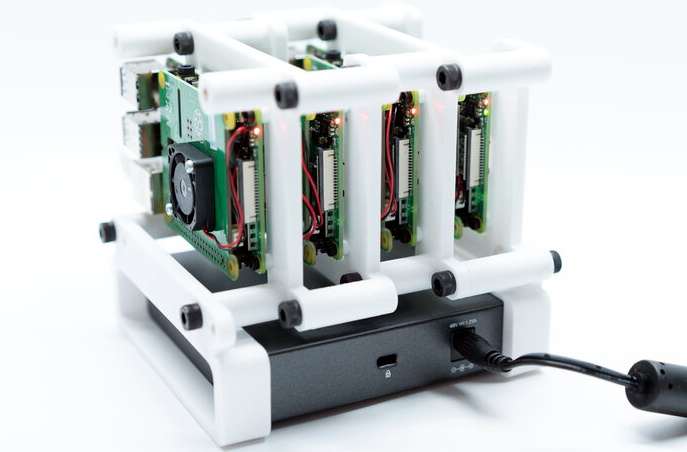
As part of his work with decentralized cryptocurrency, [Jay Doscher] recently found himself in need of a small research cluster. He determined that the Raspberry Pi 4 would give him the best bang for his buck, so he started work on a small self-contained cluster that could handle four of the single board computers. As we’ve come to expect given his existing body of work, the final result is compact, elegant, and well documented for anyone wishing to follow in his footsteps.
The core unit would make a great desktop cluster.
Outwardly the cluster looks quite a bit like the Mil-Plastic that he developed a few months back, complete with the same ten inch Pimoroni IPS LCD. But the internal design of the 3D printed case has been adjusted to fit four Pis with a unique staggered mounting arrangement that makes a unit considerably more compact than others we’ve seen in the past. In fact, even if you didn’t want to build the whole Cluster Deck as [Jay] calls it, just printing out the “core” itself would be a great way to put together a tidy Pi cluster for your own experimentation.
Thanks to the Power over Ethernet HAT, [Jay] only needed to run a short Ethernet cable between each Pi and the TP-Link five port switch. This largely eliminates the tangle of wires we usually associate with these little Pi clusters, which not only looks a lot cleaner, but makes it easier for the dual Noctua 80 mm to get cool air circulated inside the enclosure. Ultimately, the final product doesn’t really look like a cluster of Raspberry Pis at all. But then, we imagine that was sort of the point.
Parallel computing is a fair complex subject, and something many of us only have limited hands-on experience with. But breaking up tasks into smaller chunks and shuffling them around between different processors, or even entirely different computers, is arguably the future of software development. Looking to get ahead of the game, many people put together their own affordable home clusters to help them learn the ropes.
As part of his work with decentralized cryptocurrency, [Jay Doscher] recently found himself in need of a small research cluster. He determined that the Raspberry Pi 4 would give him the best bang for his buck, so he started work on a small self-contained cluster that could handle four of the single board computers. As we’ve come to expect given his existing body of work, the final result is compact, elegant, and well documented for anyone wishing to follow in his footsteps.
The core unit would make a great desktop cluster.
Outwardly the cluster looks quite a bit like the Mil-Plastic that he developed a few months back, complete with the same ten inch Pimoroni IPS LCD. But the internal design of the 3D printed case has been adjusted to fit four Pis with a unique staggered mounting arrangement that makes a unit considerably more compact than others we’ve seen in the past. In fact, even if you didn’t want to build the whole Cluster Deck as [Jay] calls it, just printing out the “core” itself would be a great way to put together a tidy Pi cluster for your own experimentation.
Thanks to the Power over Ethernet HAT, [Jay] only needed to run a short Ethernet cable between each Pi and the TP-Link five port switch. This largely eliminates the tangle of wires we usually associate with these little Pi clusters, which not only looks a lot cleaner, but makes it easier for the dual Noctua 80 mm to get cool air circulated inside the enclosure. Ultimately, the final product doesn’t really look like a cluster of Raspberry Pis at all. But then, we imagine that was sort of the point.
Parallel computing is a fair complex subject, and something many of us only have limited hands-on experience with. But breaking up tasks into smaller chunks and shuffling them around between different processors, or even entirely different computers, is arguably the future of software development. Looking to get ahead of the game, many people put together their own affordable home clusters to help them learn the ropes.
As part of his work with decentralized cryptocurrency, [Jay Doscher] recently found himself in need of a small research cluster. He determined that the Raspberry Pi 4 would give him the best bang for his buck, so he started work on a small self-contained cluster that could handle four of the single board computers. As we’ve come to expect given his existing body of work, the final result is compact, elegant, and well documented for anyone wishing to follow in his footsteps.
The core unit would make a great desktop cluster.
Outwardly the cluster looks quite a bit like the Mil-Plastic that he developed a few months back, complete with the same ten inch Pimoroni IPS LCD. But the internal design of the 3D printed case has been adjusted to fit four Pis with a unique staggered mounting arrangement that makes a unit considerably more compact than others we’ve seen in the past. In fact, even if you didn’t want to build the whole Cluster Deck as [Jay] calls it, just printing out the “core” itself would be a great way to put together a tidy Pi cluster for your own experimentation.
Thanks to the Power over Ethernet HAT, [Jay] only needed to run a short Ethernet cable between each Pi and the TP-Link five port switch. This largely eliminates the tangle of wires we usually associate with these little Pi clusters, which not only looks a lot cleaner, but makes it easier for the dual Noctua 80 mm to get cool air circulated inside the enclosure. Ultimately, the final product doesn’t really look like a cluster of Raspberry Pis at all. But then, we imagine that was sort of the point.
While you might think of radar pointing toward the skies, applications for radar have found their way underground as well. Ground-penetrating radar (GPR) is a tool that sends signals into the earth and measures their return to make determinations about what’s buried underground in much the same way that distant aircraft can be located or identified by looking for radar reflections. This technology can also be built with a few common items now for a relatively small cost.
This is a project from [Mirel] who built the system around a Arduino Mega 2560 and antipodal Vivaldi antennas, a type of directional antenna. Everything is mounted into a small cart that can be rolled along the ground. A switch attached to the wheels triggers the radar at regular intervals as it rolls, and the radar emits a signal and listens to reflections at each point. It operates at a frequency range from 323 MHz to 910 MHz, and a small graph of what it “sees” is displayed on an LCD screen that is paired to the Arduino.
Using this tool allows you to see different densities of materials located underground, as well as their depths. This can be very handy when starting a large excavation project, detecting rock layers or underground utilities before digging. [Mirel] made all of the hardware and software open-source for this project, and if you’d like to see another take on GPR then head over to this project which involves a lot of technical discussion on how it works.
One of the pleasures of consuming old science fiction movies and novels is that they capture the mood of the time in which they are written. Captain Kirk was a 1960s guy and Picard was a 1990s guy, after all. Cold war science fiction often dealt with invasion. In the 1960s and 70s, you were afraid of losing your job to a computer, so science fiction often had morality tales of robots running amok, reminding us what a bad idea it was to give robots too much power. As it turns out, robots might be dangerous, but not for the reasons we thought. The robots won’t turn on us by themselves. But they could be hacked. To that end, there’s a growing interest in robot cybersecurity and Alias Robotics is releasing Alurity, a toolbox for robot cybersecurity.
Currently, the toolbox is available for Linux and MacOS with some support for Windows. It targets 25 base robots including the usual suspects. There’s a white paper from when the product entered testing available if you want more technical details.
We aren’t clear about the licensing details of Alurity. There is a GitHub repo that has some components, and there is mention of an individual license and an educational one, but no real details about pricing. However, the repo has some interesting items including the RVD or Robot Vulnerability Database, that is worth reading (the issues, not the code) if you are working with industrial robots.
If you are satisfied that your robot is off the grid and physically secure, maybe you don’t care. However, the cybersecurity world is full of stories of bad actors breaking into something as innocuous as a thermostat or camera and then pivoting into business and industrial control networks that were considered highly secure. No one wants to be that story in tomorrow’s newspaper. Of course, you can get cybersecurity insurance, but good luck getting it to pay out.
We often see press releases and announcements about the next big technology in batteries, memory, displays, capacitors, or any of a number of other things. Usually we are suspicious since we typically don’t see any of this new technology in the marketplace over any reasonable timescale. So when we read about correlated-electron memoryCerfe Labs, we had to wonder if it would be more of the same. IOur suspicions may be justified of course, but it is telling that the company is a spin-off from ARM, so that gives them some real-world credibility.
Correlated-electron RAM or CeRAM is the usual press release material. Nonvolatile, smaller than SRAM, and fast. It sounds as though it could replace the SRAM in PC caches, for example, and take up less die space on the CPU chip. The principle is a bit odd. When electrons are forced together in certain materials, the properties of the material can change. This Mott transition (named after the inventor [Neville Mott]) can take carbon-doped nickel oxide and switch it from its natural electrical insulating state to a conducting state and back again.
Whereas a traditional static RAM cell requires up to six transistors, a Mott cell is just a bit of material and one transistor. Speedwise it seems devices exist with 2ns write cycle, something they expect to get better with more work. We’ve read that the material changes state within 100 femtoseconds. There are some other tantalizing features. The memory appears to work at very cold temperatures (like, cryogenic temperatures) and very hot temperatures, as well. It also may be radiation resistance and can be made to operate on very low voltages.
The new company doesn’t plan to actually build devices but wants to develop the technology to the point that a major manufacturer will take over the technology and bring it to market. There are doubtlessly many hurdles to putting something like this in real production and it is yet unknown if the devices can be written to repeatedly without degradation.
The idea of building a suit that increases the wearer’s strength is a compelling one, often featured in science fiction. There are a handful of real world examples, and [Alex] can now add his to the list. The build comes with a twist however, relying on hydrogen to do the work.
At its heart, the build is not dissimilar to other artificial muscle projects. The muscles in [Alex’s] build consist of a rubber tube inside a nylon braid. When the rubber tube is inflated, it expands, causing the nylon braid to shorten as it grows wider. Commonly, such builds rely on compressed air to power the muscles, however [Alex] took a different path. Instead, water is electrolysed in a chamber designed to look like Iron Man’s arc reactor, with the resulting gases produced being used to drive the muscles. With five muscles ganged up to pull together, the wearable arm support is capable of generating up to 15 kg of pull force.
It’s a design that has a few benefits; the electrolyser has no moving parts, and is much simpler and quieter than a typical air compressor. Obviously, there is a risk of fire thanks to the flammable gases used, but [Alex] explains the precautions taken to minimise this risk in the video.
Exosuits may not be mainstream just yet, but that doesn’t mean people aren’t working to make them a reality. We’ve featured a few before, like this open-source design. Video after the break.
When was the last time you tried listening to a new genre of music, or even explored a sub-genre of something you already like? That’s what we thought. It’s good to listen to other stuff once in a while and remind ourselves that there’s a whole lot of music out there, and our tastes are probably not all that diverse. As a reminder, [sorghum] made a spiffy little Spotify remote that can cruise through the musical taxonomy that is Every Noise at Once and control any Spotify-enabled device.
There’s a lot to like about this little remote, which is based upon a LilyGo TTGO ESP32 board with on-board display. The circuitry is basically that and a rotary encoder plus a tiny LiPo battery. Can we talk about the finish on those prints? Yes, those are both printed enclosures. Getting that buttery smooth finish took two grits of wet/dry sandpaper plus nine grits of polishing cloths.
As you can see in the brief demo after the break, there are several ways to discover new music. [sorghum] can surf through all kinds of Japanese music for example, or surf by the genre’s ending word and listen to metalcore, deathcore, and grindcore from all over the globe. For extra fun, there’s a genre-ending randomizer so you can discover just how many forms of *core there are.
When was the last time you tried listening to a new genre of music, or even explored a sub-genre of something you already like? That’s what we thought. It’s good to listen to other stuff once in a while and remind ourselves that there’s a whole lot of music out there, and our tastes are probably not all that diverse. As a reminder, [sorghum] made a spiffy little Spotify remote that can cruise through the musical taxonomy that is Every Noise at Once and control any Spotify-enabled device.
There’s a lot to like about this little remote, which is based upon a LilyGo TTGO ESP32 board with on-board display. The circuitry is basically that and a rotary encoder plus a tiny LiPo battery. Can we talk about the finish on those prints? Yes, those are both printed enclosures. Getting that buttery smooth finish took two grits of wet/dry sandpaper plus nine grits of polishing cloths.
As you can see in the brief demo after the break, there are several ways to discover new music. [sorghum] can surf through all kinds of Japanese music for example, or surf by the genre’s ending word and listen to metalcore, deathcore, and grindcore from all over the globe. For extra fun, there’s a genre-ending randomizer so you can discover just how many forms of *core there are.
We have no idea whether [Nick Goodey] is a trained engineer or not. But given the detailed design of this DIY energy recovery ventilator for his home HVAC system, we’re going to go out on a limb and say he probably knows what he’s doing.
For those not in the know, an energy recovery ventilator (ERV) is an increasingly common piece of equipment in modern residential and commercial construction. As buildings have become progressively “tighter” to decrease heating and cooling energy losses to the environment, the air inside them has gotten increasingly stale. ERVs solve the problem by bringing fresh, unconditioned air in from the outside while venting stale but conditioned air to the outside. The two streams pass each other in a heat exchanger so that much of the energy put into the conditioned air is transferred to the incoming unconditioned air.
While ERV systems are readily available commercially, [Nick] decided to roll his own after a few experiments with Coroplast and some extensive calculations convinced him it would be a viable idea. One may scoff at the idea of corrugated plastic for the heat exchanger, but the smooth channels through the material make it a great choice. He built up a block of Coroplast squares with the channels in alternate layers oriented orthogonally, letting stale inside air pass very close to fresh outside air to exchange heat without every mixing directly. The entire system, including fans, an Arduino for control, sensors galore, and the Hubitat home automation hub, is powered by DC, so no electrician was needed. [Nick] has a ton of detail in his build log, including all the tools and calculators he used to design the system.
Given the expense of ERV systems, we’re surprised we haven’t seen more stories about DIY versions. We have talked about HVAC systems a lot, though — after all, HVAC techs are hackers who make housecalls.
Despite the popularity of social media, for communication that actually matters, e-mail reigns supreme. Crucial to the smooth operation of businesses worldwide, it’s prized for its reliability. Google is one of the world’s largest e-mail providers, both with its consumer-targeted Gmail product as well as G Suite for business customers [Jeffrey Paul] is a user of the latter, and was surprised to find that URLs in incoming emails were being modified by the service when fetched via the Internet Message Access Protocol (IMAP) used by external email readers.
This change appears to make it impossible for IMAP users to see the original email without logging into the web interface, it breaks verification of the cryptographic signatures, and it came as a surprise.
Security Matters
A test email sent to verify the edits made by Google’s servers. Top, the original email, bottom, what was received.
For a subset of users, it appears Google is modifying URLs in the body of emails to instead go through their own link-checking and redirect service. This involves actually editing the body of the email before it reaches the user. This means that even those using external clients to fetch email over IMAP are affected, with no way to access the original raw email they were sent.
The security implications are serious enough that many doubted the initial story, suspecting that the editing was only happening within the Gmail app or through the web client. However, a source claiming to work for Google confirmed that the new feature is being rolled out to G Suite customers, and can be switched off if so desired. Reaching out to Google for comment, we were directed to their help page on the topic.
The stated aim is to prevent phishing, with Google’s redirect service including a link checker to warn users who are traveling to potentially dangerous sites. For many though, this explanation doesn’t pass muster. Forcing users to head to a Google server to view the original URL they were sent is to many an egregious breach of privacy, and a security concern to boot. It allows the search giant to further extend its tendrils of click tracking into even private email conversations. For some, the implications are worse. Cryptographically signed messages, such as those using PGP or GPG, are broken by the tool; as the content of the email body is modified in the process, the message no longer checks out with respect to the original signature. Of course, this is the value of signing your messages — it becomes much easier to detect such alterations between what was sent and what was received.
Inadequate Disclosure
Understandably, many were up in arms that the company would implement such a measure with no consultation or warning ahead of time. The content of an email is sacrosanct, in many respects, and tampering with it in any form will always be condemned by the security conscious. If the feature is a choice for the user, and can be turned off at will, then it’s a useful tool for those that want it. But this discovery was a surprise to many, making it hard to believe it was adequately disclosed before roll-out. The question unfolded in the FAQ screenshot above hints at this being part of Google’s A/B test and not applied to all accounts. Features being tested on your email account should be disclosed yet they are not.
Protecting innocent users against phishing attacks is a laudable aim, and we can imagine many business owners enabling such a feature to avoid phishing attacks. It’s another case where privacy is willingly traded for the idea of security. While the uproar is limited due to the specific nature of the implementation thus far, we would expect further desertion of Google’s email services by the tech savvy if such practices were to spread to the mainstream Gmail product. Regardless of what happens next, it’s important to remember that the email you read may not be the one you were sent, and act accordingly.
Our old math teacher famously said, “You have to take what you know and use it find what you don’t know.” The same holds true for a lot of microcontroller designs including [rgco’s] clever metal detector that uses very little other than an Arduino. The principle of operation is simple. An Arduino can measure time, a coil and a resistor will create a delay proportional to the circuit values, and metal around the coil will change the coil’s inductance. As the inductance changes, so does the delay and, thus, the Arduino can sense metal, as you can see in the video below.
The simple principle is also simple in practice. Besides the Arduino and the coil, there’s a single resistor. You want a small coil since larger coils won’t detect smaller objects. If you don’t want to wind your own coil, [rgco] suggests using a roll of hookup wire as long as the resistance is under 10 ohms.
You could omit it, but the original design has a buzzer and an electrolytic capacitor connected to generate a buzz in addition to the built-in LED indicator when metal is near. The LED also shows a blink pattern if the coil is open, too short, too long, or has too much resistance.
The biggest problem is that the poor Arduino needs to measure delays down in the nanosecond range. It can’t actually do this directly, so the code takes a ranging measurement to get in the ballpark and then produces appropriately-sized pulses and adds them up to get a better idea of the total delay. There are several videos in the post of a prototype and the final device built in a Tic Tac container, which you can see below.
Decapsulating ICs used to be an exotic technique. (I should know, I did that professionally for one of the big IC vendors back in the 1980s.) These days, more and more people are learning to take apart ICs for a variety of reasons. If you are interested in doing it yourself, [Juan Carlos Jimenez] has a post you should read about using acid to remove epoxy from ICs.
[Juan Carlos] used several different techniques with varying degrees of success. Keep in mind, that using nitric acid is generally pretty nasty. You need safety equipment and be sure to plan for bad things to happen. Have eyewash ready because once you splash acid in your eye, it is too late to get that together.
We never took apart MEMS devices, so that was especially interesting. A little metal lid keeps the epoxy out of the moving parts and that turns out to be hard to remove.
We were surprised he used 69% nitric. We used to use white fuming nitric, but that may be a bit harder to get now since it is associated with explosives. Then again, you can make it yourself. We used to also use copper bars to sit between the hot plate and the device to get better heat transfer. The acid reaction is much stronger when you heat it.
By the way, if you ever wanted to actually probe the device, you’d have to remove the passivation layer which is SiO2 glass. That takes hydrofluoric acid which is very nasty stuff, indeed. You can see the edge of the passivation around the bond pads under a microscope. You’ll notice the surface of the pad focuses differently than the edge where the thin passivation layer starts. When you can’t see that edge anymore, you’ve removed the glass.
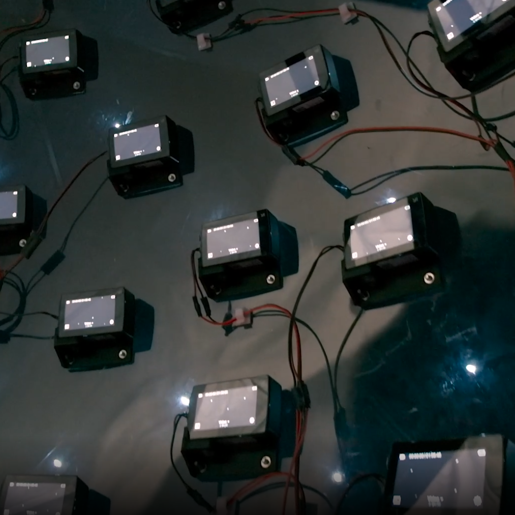
46 time-synchronized action cameras make up the guts of the capture device.
3D video content has a significant limitation, one that is not trivial to solve. Video captured by a camera — even one with high resolution and a very wide field of view — still records a scene as a flat plane, from a fixed point of view. The limitation this brings will be familiar to anyone who has watched a 3D video (or “360 video”) in VR and moved their head the wrong way. In these videos one is free to look around, but may not change the position of their head in the process. Put another way, pivoting one’s head to look up, down, left, or right is fine. Moving one’s head higher, lower, closer, further, or to the side? None of that works. Natural movements like trying to peek over an object, or moving slightly to the side for a better view simply do not work.
Light field image, with viewer’s point of view moving in a figure eight pattern. Colors show depth layers interpolated by software.
The meta-camera is a hemisphere just under one meter in diameter that contains an array of 46 time-synchronized action cameras pointed outwards. On the software end, camera input is used to reconstruct the scene and create a 6 DoF volumetric video. In other words, the perspective of the video correctly changes depending on a user moving their point of view (within an area very roughly corresponding to the size of the camera device, anyway.)
The other significant improvement is in compression and rendering of the resulting video. By reducing the video down to a small, fixed number of depth layers to represent the light field content, conventional video encoding and compression can be leveraged to deliver lightweight representations that can render easily on just about any platform. A picture is worth a thousand words, so here is a short animation showing a light field image. The point of view moves in a figure eight, and the perspectives and sight lines all change exactly as one would expect them to. The animation also briefly peeks behind the curtain, showing the color-coded depth layers that the software uses to decide what belongs where.
You can download the PDF of the SIGGRAPH 2020 technical paper, or browse the DeepView resource page hosted on GitHub for plenty of in-browser demos and a downloadable VR headset demo. The team’s video presentation is also embedded below, and gives an excellent overview.
In the eight years or so since the Raspberry Pi first landed as tangible hardware, we’ve all dealt with the Pi folks whether as customers or through their many online support and outreach activities. They’ve provided our community with the seed that led to an explosion of inexpensive Linux-capable single board computers, while their own offerings have powered so many of the projects we have featured here. Their heart lies in their educational remit, but they have also become an indispensable part of our community.
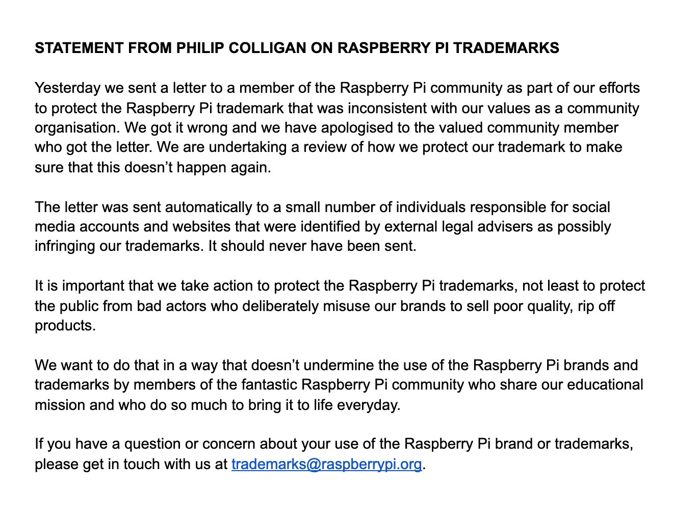
The statement from the Pi Foundation’s Philip Colligan.
Thus it was a surprise when [Raspberry Pi Spy], a long-time commentator on all things Pi, received a legal notice from the Raspberry Pi Foundation that their use of the Raspberry Pi name contravened the acceptable use guidelines and demanding that all content be removed and the domains be handed over. Some consternation ensued, before Pi foundation boss [Philip Colligan] released a statement retracting the original letter and explaining that the incident was the result of an over-zealous legal adviser and that the Foundation has no wish to undermine the Pi community.
All’s well that ends well, but what just happened? In the first instance, it’s natural for any organisation to wish to protect their brand, and there would be plenty of unscrupulous entities ready to sell fake Pi products were the Foundation not active in asserting their rights. In this case it seems that it was the use of the full Raspberry Pi trademark in a domain name that triggered the letter and not the fair-use blogging about the Pi products. We can see that however much we might wish otherwise it was not without legal merit. There have been numerous cybersquatting cases heard since the creation of the Web, and even though some of them have been on more dubious ground than others it remains a well-trodden path.
Where this story differs from so many others though is that the Pi Foundation acted with common sense in withdrawing the notice issued against a member of its community. It is inevitable that sometimes even the best of us can take regrettable paths by whatever means, and respect is earned by how such situations are resolved. We applaud the Pi folks for their swift action in this matter, we’d suggest to anyone that they take care when registering domain names, and we suspect that somewhere a legal adviser will be in the doghouse. But that all such incidents in our community could be resolved with such ease.
After a four year trek through deep space, OSIRIS-REx made history this evening as it became the first NASA spacecraft to try and collect a surface sample from an asteroid (Editor’s note: servers may be down due to the breaking news). Once sensors verify the collected material is safely onboard, the vehicle will begin drifting away from the 490 meter wide Bennu in preparation of its eventual departure and return to Earth. If all goes according to plan, the craft’s conical Sample Return Capsule carrying its precious cargo will renter the atmosphere and land at the Utah Test and Training Range in September of 2023.
OSIRIS-REx with solar panels in “Y-Wing” configuration.
Due to its extremely low gravity and rocky surface, a traditional landing on Bennu was deemed impractical. Instead, OSIRIS-REx performed a daring touch and go maneuver that brought the spacecraft into contact with the surface for just a few seconds.
A camera on the bottom of the vehicle took images every few minutes during the descent and ran them through an onboard system called Natural Feature Tracking (NFT) that autonomously steered it away from dangerous surface features. As a precaution, the solar panels on the OSIRIS-REx were angled backwards in a “Y-Wing” configuration shortly before the descent to help protect them from striking the surface or being damaged by ejected material.
Once the colander-like Touch-And-Go Sample Acquisition Mechanism (TAGSAM) mounted to the end of the spacecraft’s 3.35 meter (11 foot) articulated robotic arm arm made contact with the regolith, pressurized nitrogen was used to kick up material and push it towards storage caches built into the mechanism. With so much riding on the successful collection of surface material, this largely passive system was selected to minimize the possible failures in the critical few seconds that OSIRIS-REx would be in contact with Bennu. Mission planners say it might take until Saturday to determine if a sample was successfully collected, and that the spacecraft has the ability to perform two more attempts if needed.
You’d be forgiven for assuming that a Tesla coil is some absurdly complex piece of high-voltage trickery. Clarke’s third law states that “any sufficiently advanced technology is indistinguishable from magic”, and lighting up a neon tube from across the room sure looks a lot like magic. But in his latest Plasma Channel video, [Jay Bowles] tries to set the record straight by demonstrating a see-through Tesla coil that leaves nothing to the imagination.
Of course, we haven’t yet mastered the technology required to produce transparent copper wire, so you can’t actually see through the primary and secondary coils themselves. But [Jay] did wind them on acrylic tubes to prove there aren’t any pixies hiding in there. The base of the coil is also made out of acrylic, which lets everyone see just how straightforward the whole thing is.
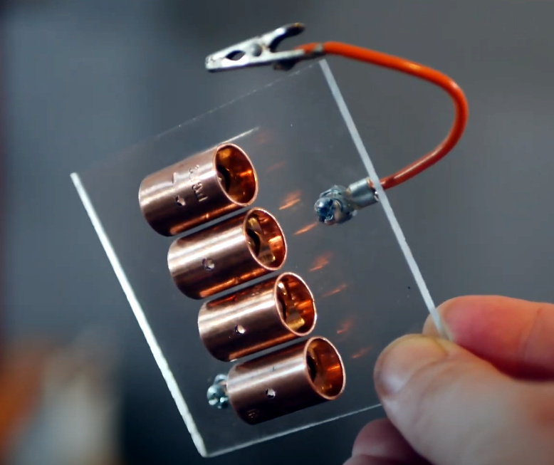
Beyond the coils, this build utilizes the DIY high-voltage power supply that [Jay] detailed a few months back. There’s also a bank of capacitors mounted to a small piece of acrylic, and a clever adjustable spark gap that’s made of little more than a few strategically placed pieces of copper pipe and an alligator clip. Beyond a few little details that might not be obvious at first glance, such as grounding the secondary coil to a layer of aluminum tape on the bottom of the base, it’s all right there in the open. No magic, just science.
[Jay] estimates this beauty can produce voltages in excess of 100,000 volts, and provides a demonstration of its capabilities in the video after the break. Unfortunately, before he could really put the new see-through coil through its paces, it took a tumble and was destroyed. A reminder that acrylic enclosures may be pretty, but they certainly aren’t invulnerable. With the value of hindsight, we’re sure the rebuilt version will be even better than the original.
If you’ve ever wanted to try your hand at creating a Raspberry Pi-like board for yourself, you should check out [Jay Carlson’s] review of 10 different Linux-capable SoCs. Back in the 1960s, a computer was multiple refrigerator-sized boxes with thousands of interconnections and building one from scratch was only a dream for most people. Then ICs can and put all the most important parts in a little relatively inexpensive IC package and homebrew computing became much more accessible. Systems on Chip (SoC) has carried that even further, making it easier than ever to create entire systems, like the Pi and its many competitors.
Only a few years ago, making an SoC was still a big project because the vendors often didn’t want to release documentation to the public. In addition, most of the parts use ball grid array (BGA) packaging. BGA parts can be hard to work with, and require a multilayer PC board. Sure, you can’t plug these into a typical solderless breadboard. But working with these relatively large BGAs isn’t that hard and multilayer boards are now comparatively cheap. [Jay] reports that he got cheap PCBs and used a hot plate to build each board, and has some sage advice on how to do it.
Although he’s looking at 10 different chips, he wound up making about 25 boards and he deliberately avoided using example PCB layouts. This let him optimize for hand assembly and try a few different strategies for things like memory layout. [Jay] points out the boards are more for evaluation than use. He didn’t put any peripherals onboard that you would probably want in a working system. He only included what was necessary to boot the chip into Linux.
There’s a long part of the post where [Jay] talks about why you might want to use Linux, why you might not want to use Linux, and why the Raspberry Pi 4 might not be your best choice, depending on your design goals. He also gives a tutorial on simplified single-chip DDR memory layout.
This has a reputation of being difficult to do, and the post acknowledges that for multip-chip designs, it is harder. However, at the speeds involved and the proposed topology, [Jay] was able to build several working designs and was even able to overclock the memory. The takeaway is that for all the panic over DRAM signal timing on a board, some of it may be unnecessarily strict and buying modules with RAM already in place might be unnecessarily expensive. Of course, some of that is because none of these processors are running at very high-speeds or with overly complex and fast RAM.
The first half of the post is full of information like that, but devoid of any testing of the actual parts. When you get to the bottom half, you’ll see, though, that he uses ten different chips from vendors like Microchip, ST, NXP, Ti, Allwinner, and others. We were impressed with how much work was done, including benchmarks. The actual write up is impressive, too Each part has its own quirks, like the Allwinner part that can only address the first 16MB of flash. He even threw in a video, you can see below.
If you need an oscilloscope, function generator, or other piece of kit for your electronics workbench, there are plenty of modern options. Dropping $4,000 for a modern oscilloscope is nice if you have the money, but if you’d rather put it to better use there are great options that don’t cost a fortune. There are some addons that can turn a smartphone into an oscilloscope but one of the best values out there are older pieces of equipment from the 80s that still work great. You can even upgrade them with some more modern features too, like [NFM] did with this vintage function generator.
This function generator is an HP3325A and it is several decades old, so some work was needed just to restore it to original working condition. The cooling fan and capacitors all needed to be replaced, as well as a few other odds and ends. From there [NFM] set about adding one of the two optional upgrades available for this device, the high voltage output. This allows the function generator to output 40 volts peak-to-peak at 40 milliamps. While he did have an original version from HP, he actually had a self-made design produced that matches the function of the original.
Even if you don’t have this specific function generator, this guide goes into great details about the functioning of older equipment like this. Most of the parts are replaceable and upgrades aren’t completely out of the question like some modern equipment, and with the right care and maintenance these pieces of equipment could last for decades longer.
Over the last year we’ve seen a wave of portable computer builds that center around the Raspberry Pi taking up residence inside a commercial heavy-duty storage case. It’s not hard to see why; whether you spring for the Pelican case or get a cheaper alternative, these water-tight cases are far stronger than anything you’re going to 3D print or otherwise cobble together in the home shop. Especially if you can avoid popping any holes in the side.
Inspired by these builds but looking to make it even easier and cheaper to roll your own version, [Dmitry] recently took the wraps off of what he calls the Militarish Pi. You don’t need a CNC to cut out any face plates or a 3D printer to create an internal framework for all your components. You could even do it without soldering anything, if you really wanted to. Short of just buying one of theses rigs pre-built from somebody, it’s hard to imagine it could get much easier than this.
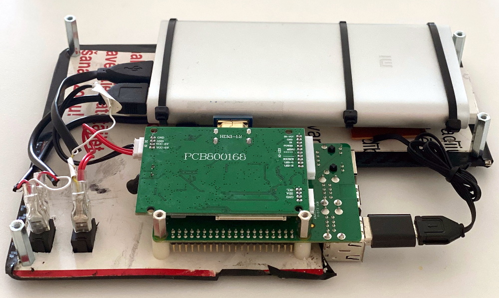
Most of the effort involves cutting the PVC foam sheet that holds the Raspberry Pi, battery pack, and the driver board for the LCD in the bottom of the $15 USD case [Dmitry] managed to track down on AliExpress. The “carbon fiber” sticker he put on the PVC sheet won’t do much for the structural integrity of the build, but it sure looks nice. Of course if you have access to the appropriate tools, you could certainly cut the plate out of something stouter. As for the display, the nine inch LCD is perfectly sized to press fit into the lid.
Rounding out the build, [Dmitry] found a cheap Android phone case that included a tiny USB keyboard which plugs right into the Pi. He’s looking to add a BlackBerry trackball to the setup down the line, but in the meantime you can always tap on the screen. We especially like the large open area that he’s kept around the Raspberry Pi’s ports that allow you to easily hook up to the network or plug in a flash drive. It could also be a nice compartment to keep your RTL-SDR for some mobile radio work.
For those that don’t mind spending name-brand money and have access to a 3D printer, the Raspberry Pi Quick Kit by [Jay Doscher] is another great way to get yourself a rough and tumble Pi without reinventing the wheel.
Over the last year we’ve seen a wave of portable computer builds that center around the Raspberry Pi taking up residence inside a commercial heavy-duty storage case. It’s not hard to see why; whether you spring for the Pelican case or get a cheaper alternative, these water-tight cases are far stronger than anything you’re going to 3D print or otherwise cobble together in the home shop. Especially if you can avoid popping any holes in the side.
Inspired by these builds but looking to make it even easier and cheaper to roll your own version, [Dmitry] recently took the wraps off of what he calls the Militarish Pi. You don’t need a CNC to cut out any face plates or a 3D printer to create an internal framework for all your components. You could even do it without soldering anything, if you really wanted to. Short of just buying one of theses rigs pre-built from somebody, it’s hard to imagine it could get much easier than this.
Most of the effort involves cutting the PVC foam sheet that holds the Raspberry Pi, battery pack, and the driver board for the LCD in the bottom of the $15 USD case [Dmitry] managed to track down on AliExpress. The “carbon fiber” sticker he put on the PVC sheet won’t do much for the structural integrity of the build, but it sure looks nice. Of course if you have access to the appropriate tools, you could certainly cut the plate out of something stouter. As for the display, the nine inch LCD is perfectly sized to press fit into the lid.
Rounding out the build, [Dmitry] found a cheap Android phone case that included a tiny USB keyboard which plugs right into the Pi. He’s looking to add a BlackBerry trackball to the setup down the line, but in the meantime you can always tap on the screen. We especially like the large open area that he’s kept around the Raspberry Pi’s ports that allow you to easily hook up to the network or plug in a flash drive. It could also be a nice compartment to keep your RTL-SDR for some mobile radio work.
For those that don’t mind spending name-brand money and have access to a 3D printer, the Raspberry Pi Quick Kit by [Jay Doscher] is another great way to get yourself a rough and tumble Pi without reinventing the wheel.
We like to pretend that our circuits are as perfect as our schematics. But in truth, PCB traces have unwanted resistance, capacitance, and inductance. On the other hand, that means you can use those traces to build components. For example, it isn’t uncommon to see a very small value current sense resistor be nothing more than a long PC board trace. Using PC layers for decoupling capacitance and creating precise transmission lines are other examples. [IndoorGeek] takes us through his process of creating coils on the PCB using KiCad. To help, he used a Python script that works out the circles, something KiCAD has trouble with.
The idea is simple. A coil of wire has inductance even if it is a flat copper trace on a PCB. In this case, the coils are more for the electromagnetic properties, but the same idea applies if you wanted to build tuned circuits. The project took inspiration from FlexAR, an open-source flexible PCB magnet.
KiCAD doesn’t like curved traces, but since the file format is open and text-based, it is easy to write scripts that can create shapes for you. [Joan Spark] provided the script. By the way, the goal for these magnets is to improve the mechanical 7-segment display we’ve looked at earlier.
It is really great to be able to work with text files and modify your PCB layouts; it leads to very handy tools. Of course, you can do the same kinds of tricks with gcode, but by that time, you’ve lost a lot of information.
If there’s any holiday that is worth adjusting for strange times, it’s gotta be Halloween. Are you inclined to leave a bowl of candy on the porch to avoid the doorbell? If so, this is the perfect year to finally figure out some sort of metering apparatus so that greedy preteens are less likely to steal your stash in one sweep. There’s still time to make something fun like [Brankly]’s automatic candy dispenser, which we think ought to stick around for many years to come. Video is posted after the break.
Underneath that skeleton’s jack-o-lantern head is the heart of this build — an orange 5-gallon bucket that matches it perfectly. Simply step on the giant lighted arcade button, and the equally giant NEMA-23 stepper motor moves a 3D-printed turntable inside the bucket with the help of an Arduino Nano. This moves the candy toward the 3D-printed ramp and out the mouth of the jack-o-lantern, where it lands in a bowl that lights up when it hits the bottom thanks to a relay and a second Nano.
[Brankly] made clever use of IR break-beam switches, which sit underneath the two square holes in the ramp. Once candy passes over one of them, the turntable stops and rotates backward to move the candy where it can’t be reached.
Frankly, we love that [Brankly] reused the sound effects module that came with the jack-o-lantern. This build is totally open, and [Brankly] is even giving away 40 PCBs if you want to make your own. For now, you can check out the code and start printing the STLs.
It’s a new year and the perfect time to get your child’s homework routine sorted out. There are various ways you can help your child be more productive and get their homework completed in a reasonable timeframe. From removing distractions to encouraging your child, there are plenty of steps you can take to make homework time easier.
Homework plays an important role in the
education of your child. It helps to develop their study skills while teaching
them responsibility. Your child will learn independence when they complete
academic tasks outside the classroom. They’ll also develop their time management
and organisational capabilities. Homework ensures that your child has a good grasp of the content
they’re learning at school.
Homework tips:
1. Remove distractions
Set up
an area in your house where your child can complete their homework in peace and
quiet. Eliminating distractions makes it easier for your child to concentrate,
which decreases the frustration that can accompany homework time.
2. Invest in tools
Make
sure your child has everything they need to get their homework done. From pens to calculators,
place all the necessary materials in the designated study area. Check whether
they have any special projects that require additional materials so you’re properly
prepared before they start their projects.
3. Establish a routine
Create
a routine where your child starts their homework at a set time every day. Don’t leave homework until the last
minute. It’s also good to encourage your child to complete projects ahead of
the deadline. This teaches your child time-management skills and will be a good
attribute he/she will apply to everything else in life.
4. Monitor progress
Monitor
homework progress by identifying what it is they have to do. Go through the homework when it has been
completed and follow up once it has been marked. Likewise, it’s helpful to
monitor your child’s test results throughout the year. Evaluating the results
gives you insight into the areas that your child might be struggling with.
You’ll be able to address these problems and get extra support if it’s
required.
5. Provide encouragement
Instead
of criticizing, rather encourage your child. Maintain a positive attitude and
keep your child motivated rather than putting pressure on them.
6. Offer support
Create
a supportive environment by doing your homework too. If your child is reading, you could
join in by reading a book. If they are doing mathematics, you could get your
finances done. While your child is doing their homework, take the time to complete any unfinished
work you might have.
7. Provide guidance
Rather
than giving your child the answers, take the opportunity to teach them instead.
While some support is beneficial, doing the work for your child prevents them
from learning. Focus on teaching your child difficult concepts to prevent them
from falling behind in the classroom.
8. Take breaks
Let
your child take a short break if they’re struggling to focus. If they’re
getting frustrated with a task, encourage them to take a time out before
getting back to the problem that he/she is working on. This ensures that your
child comes back to difficult tasks with a fresh perspective.
9. Communicate
Communicate
with your child’s teacher regularly. If you notice that your child is
struggling with something particular, let their teacher know. Teachers can
provide useful advice on how to support your child if they are having
difficulties with particular subjects. Find out the purpose of the homework and be aware of
the class rules.
10. Read to your child
Set
aside time before your child goes to sleep to read to them. While this may not
be part of the homework
routine, it’s a great opportunity to spend quality time together and encourage
reading. Ask your child questions about the story to improve their
comprehension capabilities.