DIY Induction Heater Draws 1.4 kW And Gets Metal Hot

Induction heaters can make conductive objects incredibly hot by generating eddy currents within the metal. They’re used in a wide variety of industrial processes, from furnaces to welders and even heat treatments. [Schematix] whipped up his own design, and put it through its paces on the bench.

The build in question is a fairly compact design, roughly shoebox-sized when fitted with its six-turn coil. Running off anything from 12 V to 48 V, the heater put out at a massive 1.4 kW in testing. At this power level, the high current draw led the power traces to heat up enough to melt solder, and eventually burn out. [Schematix] plans to rebuild the heater with added copper wiring along these traces to support the higher power levels without failure.

The heater is able to quickly heat ferrous metals, though was not able to meaningfully dump power into aluminium under testing. This is unsurprising, as non-ferrous metals primarily undergo only Joule heating from induction, forgoing the hysteresis portion of heat transfer due to being non-magnetic. However, modification to the design could improve performance for those eager to work with non-ferrous materials.

We’ve seen a few induction heaters before, for purposes as varied as soldering and casting. Video after the break.

source https://hackaday.com/2020/11/29/diy-induction-heater-draws-1-4-kw-and-gets-metal-hot/

Advanced Printer Control Aims To Stop Idle Waste

3D printers are capable of creating complex geometries with a minimum of fuss, but one of the tradeoffs is the long period of time it takes to print a part. Often, printers are left to run for many hours with a minimum of supervision to complete their tasks. This can leave printers idling for long periods of time after their work is finished. Noting this, [TheGrim] put together the Advanced Printer Control.

The aim of the APC is to monitor 3D printers, and shut them off when their work is complete. The aim is to avoid leaving printers running for hours after their prints are finished, which causes needless wear on fans and screens which can have a limited life. This is achieved by putting an ESP8266 in charge of the printer’s AC power supply, via a triac. It measures the current drawn by the printer when idling and in use to set a baseline. Then, whenever the printer drops back to idle levels, a timer begins. When the timer runs out, the printer is switched off. There’s also an option to automatically trigger shutdown with an I/O pin, too.

It’s a project that aims to extend printer life and save power, too. Of course, if you’re really worried about power draw, you could use a solar powered printer instead. If you’ve got your own printer controller hacks, be sure to drop us a line.

source https://hackaday.com/2020/11/29/advanced-printer-control-aims-to-stop-idle-waste/

A Clap-Activated Machine For All Your Applause Needs

Applause is greatly revered as a symbol of warmth and adoration from a crowd. TV shows that film in front of a live audience often cue their audiences to clap in order to generate the desired auditory atmosphere. Of course, you don’t have to rely on squishy humans to do all the work. [Dillon] built a machine of dubious utility – one which generates mechanical applause when activated by the sound of clapping. (Video, embedded below.)

Somewhat unsurprisingly, the project was built for a Useless Machine contest, but that doesn’t diminish its value as a learning exercise. An Arduino runs the show, using a microphone module to listen out for loud noises such as claps. If two claps are detected in the nominated timeframe, the machine begins to flash its “APPLAUSE” lights and clap its hands. The Arduino achieves this with the help of a relay, which switches on a motor spinning a belt-driven cam which seperates the hands. The hands are then pulled back together to clap via a length of stretchy bungee cord.

With an incredibly noisy drivetrain and somewhat amateur clapping ability, the sound coming from the machine isn’t exactly recognisable as “applause”. However, it’s a start, and it remains the best clapping machine we’ve seen this decade. If you’ve got your own under construction, consider dropping us a line. And if all this has you waxing nostalgic for the vintage Clapper circuit, you can always build one of those, too.

source https://hackaday.com/2020/11/29/a-clap-activated-machine-for-all-your-applause-needs/

Open Hardware GPS Tracker Works On Your Terms

These days, there’s plenty of options if you want to get a GPS tracker for your vehicle. Unfortunately, they come with the sort of baggage that’s becoming increasingly common with consumer tech: subscription fees, third-party snooping, and a sneaking suspicion that you’re more commodity than customer. So [Viktor Takacs] decided to take things into his own hands and create an open GPS tracker designed for privacy minded hackers.

As [Viktor] didn’t want to reinvent the wheel, his design leverages several off-the-shelf modules. The core of the tracker is the ESP32, which gives him plenty of computational power while still keeping energy consumption within reasonable levels. There’s also a NEO-6M GPS receiver which works at the same 3.3 V level as the ESP32, allowing the microcontroller to read the NMEA sentences without a level shifter. He decided to go with the low-cost SIM800L GSM modem, but as it only works on 2G networks, provisions have been made in the board design to swap it out for a more modern module should you desire.

For the code to glue it all together, [Viktor] pulled in nearly a dozen open source libraries to create a feature-complete firmware that uses MQTT to create a database of location data on his personal server. From there the data is plugged into Home Assistant and visualized with Grafana. This is enough to deliver core functionality, but he says that more custom software components as well as a deep-dive into the security implications of the system is coming in the near future.

We’ve seen custom built GPS trackers before, as generally speaking, it doesn’t take a whole lot to spin up your own solution. But we think the polish that [Viktor] has put on this project takes it to the next level, and ranks it up there among some of the most impressive bespoke tracking solutions we’ve seen over the years.

source https://hackaday.com/2020/11/28/open-hardware-gps-tracker-works-on-your-terms/

Open Hardware GPS Tracker Works On Your Terms

These days, there’s plenty of options if you want to get a GPS tracker for your vehicle. Unfortunately, they come with the sort of baggage that’s becoming increasingly common with consumer tech: subscription fees, third-party snooping, and a sneaking suspicion that you’re more commodity than customer. So [Viktor Takacs] decided to take things into his own hands and create an open GPS tracker designed for privacy minded hackers.

As [Viktor] didn’t want to reinvent the wheel, his design leverages several off-the-shelf modules. The core of the tracker is the ESP32, which gives him plenty of computational power while still keeping energy consumption within reasonable levels. There’s also a NEO-6M GPS receiver which works at the same 3.3 V level as the ESP32, allowing the microcontroller to read the NMEA sentences without a level shifter. He decided to go with the low-cost SIM800L GSM modem, but as it only works on 2G networks, provisions have been made in the board design to swap it out for a more modern module should you desire.

For the code to glue it all together, [Viktor] pulled in nearly a dozen open source libraries to create a feature-complete firmware that uses MQTT to create a database of location data on his personal server. From there the data is plugged into Home Assistant and visualized with Grafana. This is enough to deliver core functionality, but he says that more custom software components as well as a deep-dive into the security implications of the system is coming in the near future.

We’ve seen custom built GPS trackers before, as generally speaking, it doesn’t take a whole lot to spin up your own solution. But we think the polish that [Viktor] has put on this project takes it to the next level, and ranks it up there among some of the most impressive bespoke tracking solutions we’ve seen over the years.

source https://hackaday.com/2020/11/28/open-hardware-gps-tracker-works-on-your-terms/

Ham Radio Needs To Embrace The Hacker Community Now More Than Ever

As many a radio amateur will tell you, ham radio is a hobby with as many facets as there are radio amateurs. It should be an exciting and dynamic place to be, but as those who venture forth into it sometimes sadly find out, it can be anything but. Tightly-knit communities whose interests lie in using $1,000 stations to chase DX (long-distance contacts), an advancing age profile, and a curious fascination of many amateurs with disaster communications. It’s something [Robert V. Bolton, KJ7NZL] has sounded off about in an open letter to the amateur radio community entitled “Ham Radio Needs To Embrace The Hacker Community Now More Than Ever“.

In it he laments that the influx in particular of those for whom disaster preparedness is the reason for getting a licence is to blame for amateur radio losing its spark, and he proposes that the hobby should respond by broadening its appeal in the direction of the hacker community. The emphasis should move from emergency communications, he says, and instead topics such as software defined radio and digital modes should be brought to the fore. Finally he talks about setting up hacker specific amateur radio discussion channels, to provide a space in which the talk is tailored to our community.

Given our experience of the amateur radio community we’d be bound to agree with him. The hobby offers unrivalled opportunity for analogue, mixed-signal, digital, and software tinkering in the finest tradition of the path set by the early radio amateurs around a hundred years ago, yet it sometimes seems to have lost its way for people like us. It’s something put into words a few years ago by our colleague Dan Maloney, and if you’re following [KJ7NZL]’s path you could do worse than read Dan’s long-running $50 ham series from the start.

Via Hacker News.

Header image: Unknown author, Public domain.

source https://hackaday.com/2020/11/28/ham-radio-needs-to-embrace-the-hacker-community-now-more-than-ever/

Taking Over the Amazing Control Panel of a Vintage Video Switcher

Where does he get such wonderful toys? [Glenn] snagged parts of a Grass Valley Kalypso 4-M/E video mixer control surface from eBay and since been reverse engineering the button and display modules to bend them to his will. The hardware dates back to the turn of the century and the two modules would have been laid out with up to a few dozen others to complete a video mixing console.

[Glenn’s] previous adventures delved into a strip of ten backlit buttons and gives us a close look at each of the keyswitches and the technique he used to pull together his own pinout and schematic of that strip. But things get a lot hairier this time around. The long strip seen above is a “machine control plane” module and includes a dozen addressible character displays, driven by a combination of microcontrollers and FPGAs. The square panel is a “Crosspoint Switch Matrix” module include eight individual 32 x 32 LCDs drive by three dedicated ICs that can display in red, green, or amber.

[Glen] used an STM8 Nucleo 64 to interface with the panels and wrote a bit of code to help map out what each pin on each machine control plane connector might do. He was able to stream out some packets from the plane that changed as he pressed buttons, and ended up feeding back a brute-force of that packet format to figure out the LED display protocols.

But the LCDs on the crosspoint switch were a more difficult nut to crack. He ended up going back to the original source of the equipment (eBay) to get a working control unit that he could sniff. He laid out a man-in-the-middle board that has a connector on either side with a pin header in the middle for his logic analyzer. As with most LCDs, the secret sauce was the initialization sequence — an almost impossible thing to brute force, yet exceedingly simple to sniff when you have a working system. So far he has them running under USB control, and if you are lucky enough to have some of this gear in your parts box, [Glen] has painstakingly recorded all of the details you need to get them up and running.

source https://hackaday.com/2020/11/28/taking-over-the-amazing-control-panel-of-a-vintage-video-switcher/

Scratch Building a Supersized CNC Router

Many of us have spent the better part of a year on COVID-19 lockdown, and what do we have to show for it? Bit of progress on the Netflix queue? Maybe a (slightly) cleaned up garage or workshop? Not if you’re [Bob] of Making Stuff fame: he’s spent the last nine months working on a completely custom CNC router big enough to take a whole sheet of plywood.

The build is documented over a series of nearly a dozen YouTube videos, the first of which was put out all the way back in January of 2020. Seeing [Bob] heading to the steel mill to get his frame components with nary a mask in sight is a reminder of just how long he’s been working on this project. He’s also put together a comprehensive Bill of Materials on his website should anyone want to follow in his footsteps. Coming in at only slightly less than $4,000 USD, it’s certainly not a budget build. But then when we’re talking about a machine of this scale, nothing comes cheap.

Every component on this build is heavy-duty.

Even if you don’t build you own version of this router, it’s impossible to watch the build log and not get inspired about the possibilities of such a machine. In the last video we’re even treated to a bit of self-replicating action, as the jumbo CNC cuts out the pieces for its own electronics enclosure.

You can tell from the videos that [Bob] is (rightfully) proud of his creation, and isn’t shy about showing the viewer each and every triumph along the way. Even when things don’t go according to plan, there are lessons to be learned as he explains the problems and how they were ultimately resolved.

Of course, we know a home-built CNC router doesn’t need to cost thousands of dollars or take up as much space as a pool table. The average Hackaday reader probably has no need of a monster like this, and wouldn’t have anywhere to keep it even if they did. But that doesn’t mean we can’t look on with envy as we wait to see what kind of projects [Bob] churns out with such an incredible tool in his arsenal.

source https://hackaday.com/2020/11/28/scratch-building-a-supersized-cnc-router/

This Debug Connector Brings Your Issues to the Edge

Given an unknown PCBA with an ARM processor, odds are good that it will have either the standard 10 pin 0.05″ or 20 pin 0.1″ debug connector. This uncommon commonality is a boon for an exploring hacker, but when designing a board such headers require board space in the design and more components to be installed to plug in. The literally-named Debug Edge standard is a new libre attempt to remedy this inconvenience.

The name “Debug Edge” says it all. It’s a debug, edge connector. A connector for the edge of a PCBA to break out debug signals. Card edge connectors are nothing new but they typically either slot one PCBA perpendicularly into another (as in a PCI card) or hold them in parallel (as in a mini PCIe card or an m.2 SSD). The DebugEdge connector is more like a PCBA butt splice.

It makes use of a specific family of AVX open ended card edge connectors designed to splice together long rectangular PCBAs used for lighting end to end. These are available in single quantities starting as low as $0.85 (part number for the design shown here is 009159010061916). The vision of the DebugEdge standard is that this connector is exposed along the edge of the target device, then “spliced” into the debug connector for target power and debug.

Right now the DebugEdge exists primarily as a standard, a set of KiCAD footprints, and prototype adapter boards on OSHPark (debugger side, target side). A device making use of it would integrate the target side and the developer would use the debugger side to connect. The standard specifies 4, 6, 8, and 10 pin varieties (mapping to sizes of available connector, the ‘010’ in the number above specifies pincount) offering increasing levels of connectivity up to a complete 1:1 mapping of the standard 10 pin ARM connector. Keep in mind the connectors are double sided, so the 4 pin version is a miniscule 4mm x 4.5mm! We’re excited to see that worm its way into a tiny project or two.

We’ve seen plenty of part-free debug and programming connectors before. Have a favorite? Let us know in the comments!

source https://hackaday.com/2020/11/28/this-debug-connector-brings-your-issues-to-the-edge/

This Debug Connector Brings Your Issues to the Edge

Given an unknown PCBA with an ARM processor, odds are good that it will have either the standard 10 pin 0.05″ or 20 pin 0.1″ debug connector. This uncommon commonality is a boon for an exploring hacker, but when designing a board such headers require board space in the design and more components to be installed to plug in. The literally-named Debug Edge standard is a new libre attempt to remedy this inconvenience.

The name “Debug Edge” says it all. It’s a debug, edge connector. A connector for the edge of a PCBA to break out debug signals. Card edge connectors are nothing new but they typically either slot one PCBA perpendicularly into another (as in a PCI card) or hold them in parallel (as in a mini PCIe card or an m.2 SSD). The DebugEdge connector is more like a PCBA butt splice.

It makes use of a specific family of AVX open ended card edge connectors designed to splice together long rectangular PCBAs used for lighting end to end. These are available in single quantities starting as low as $0.85 (part number for the design shown here is 009159010061916). The vision of the DebugEdge standard is that this connector is exposed along the edge of the target device, then “spliced” into the debug connector for target power and debug.

Right now the DebugEdge exists primarily as a standard, a set of KiCAD footprints, and prototype adapter boards on OSHPark (debugger side, target side). A device making use of it would integrate the target side and the developer would use the debugger side to connect. The standard specifies 4, 6, 8, and 10 pin varieties (mapping to sizes of available connector, the ‘010’ in the number above specifies pincount) offering increasing levels of connectivity up to a complete 1:1 mapping of the standard 10 pin ARM connector. Keep in mind the connectors are double sided, so the 4 pin version is a miniscule 4mm x 4.5mm! We’re excited to see that worm its way into a tiny project or two.

We’ve seen plenty of part-free debug and programming connectors before. Have a favorite? Let us know in the comments!

source https://hackaday.com/2020/11/28/this-debug-connector-brings-your-issues-to-the-edge/

Sims-Style Plumb Bob Broadcasts Your Mood

While there are a lot of objects from the Sims that we wish were real, we probably wish more than anything that everyone had a mood indicator hovering above their heads at all times. It would make working from home go a lot more smoothly, for instance. [8BitsAndAByte] made this Bluetooth-controlled plumb bob as part of their Sims Halloween costume, but we think it has real day-to-day value as this pandemic wears on, either as a mood ring or a portable free/busy indicator.

The hardware is about as simple as it gets — an Adafruit Feather nRF52 Bluefruit controls a pair of NeoPixel rings, one for each half of the translucent 3D-printed plumb bob. Power comes from a 500mAh battery, and all the electronics are situated inside of an attractive hat. Check out the build video after the break.

There’s more than one way to use color to convey information. This seven-segment temperature display does it with thermochromic film.

source https://hackaday.com/2020/11/28/sims-style-plumb-bob-broadcasts-your-mood/

TMD-2: A Bigger, Better, More Collaborative Turing Machine

One of the things we love best about the articles we publish on Hackaday is the dynamic that can develop between the hacker and the readers. At its best, the comment section of an article can be a model of collaborative effort, with readers’ ideas and suggestions making their way into version 2.0 of a build.

This collegial dynamic is very much on display with TMD-2, [Michael Gardi]’s latest iteration of his Turing machine demonstrator. We covered the original TMD-1 back in late summer, the idea of which was to serve as a physical embodiment of the Turing machine concept. Briefly, the TMD-1 represented the key “tape and head” concepts of the Turing machine with a console of servo-controlled flip tiles, the state of which was controlled by a three-state, three-symbol finite state machine.

TMD-1

TMD-1 was capable of simple programs that really demonstrated the principles of Turing machines, and it really seemed to catch on with readers. Based on the comments of one reader, [Newspaperman5], [Mike] started thinking bigger and better for TMD-2. He expanded the finite state machine to six states and six symbols, which meant coming up with something more scalable than the Hall-effect sensors and magnetic tiles of TMD-1.

TMD-2 has a camera for computer vision of the state machine tiles

[Mike] opted for optical character recognition using a Raspberry Pi cam along with Open CV and the Tesseract OCR engine. The original servo-driven tape didn’t scale well either, so that was replaced by a virtual tape displayed on a 7″ LCD display. The best part of the original, the tile-based FSM, was expanded but kept that tactile programming experience.

Hats off to [Mike] for tackling a project with so many technologies that were previously new to him, and for pulling off another great build. And kudos to [Newspaperman5] for the great suggestions that spurred him on.

source https://hackaday.com/2020/11/28/tmd-2-a-bigger-better-more-collaborative-turing-machine/

HackRF PortaPack Firmware Spoofs All the Things

The HackRF is an exceptionally capable software defined radio (SDR) transceiver, but naturally you need to connect it to a computer to actually do anything with it. So the PortaPack was developed to turn it into a stand-alone device with the addition of a touchscreen LCD, a few buttons, and a headphone jack. With all the hardware in place, it’s just a matter of installing a firmware capable enough to do some proper RF hacking on the go.

Enter MAYHEM, an evolved fork of the original PortaPack firmware that the developers claim is the most up-to-date and feature packed version available. Without ever plugging into a computer, this firmware allows you to receive, decode, and re-transmit a dizzying number of wireless protocols. From firing off the seating pagers at a local restaurant to creating a fleet of phantom aircraft with spoofed ADS-B transponders, MAYHEM certainly seems like it lives up to the name.

[A. Petazzoni] recently put together a detailed blog post about installing and using MAYHEM on the HackRF/PortaPack, complete with a number of real-world examples that show off just a handful of possible applications for the project. Jamming cell phones, sending fake pager messages, and cloning RF remotes is just scratching the surface of what’s possible.

It’s not hard to see why some have already expressed concern about the project, but in reality, none of these capabilities are actually new. This firmware simply brings them all together in one easy-to-use package, and while there might be an argument to be made about proliferation, we all know that the responsibility to behave ethically rests on the user and not the tools.

source https://hackaday.com/2020/11/28/hackrf-portapack-firmware-spoofs-all-the-things/

An iMac All-In-One’s New Life

There’s a sleek form factor for desktop computers known as an “all-in-one” that enrobes a computer in a monitor. While the convenience of having all your computing in a neat package has some nice benefits, it comes with an unfortunate downside. Someday the computer inside is going to be old and outdated in comparison to newer machines. While a new OS goes a long way towards breathing life into an old machine, [Thomas] has decided to take the path less travelled and converted an old iMac all-in-one into a discrete monitor.

The iMac in question is the 20″ iMac G5 iSight (A1145) with an LG-Philips LM201W01-STB2 LCD panel. Looking back, [Thomas] would recommend just ordering an LCD driver controller kit from your favourite auction house. But for this particular modification, he decided to do things a little bit more manually and we’re quite glad he did.

Luckily for [Thomas], the panel supports TMDS (which both DVI and HDMI are compatible with). So the next step was to figure out the signalling wires and proper voltages. After some trouble caused by a mislabeled power line on the iMac PCB silk-screen (12v instead of 3.3v), he had all the wires identified and a plan starting to form. The first step was a circuit to trick the inverter into turning on with the help of a relay. The female HDMI plug with a breakout board was added and sticks out through the old firewire port. The minuscule wires in the display ribbon cable to the monitor were separated and soldered onto with the help of [Thomas’] daughter’s microscope. Resistances were checked as HDMI relies on impedance matched pairs. To finish it off, an old tactile toggle switch offers a way to turn the monitor on and off with a solid thunk.

We love seeing old hardware being repurposed for new things. This project nicely complements the iMac G4 Reborn With Intel NUC Transplant we saw earlier this year, as they both try to preserve the form factor while allowing a new computer to drive the display.

source https://hackaday.com/2020/11/27/an-imac-all-in-ones-new-life/

An iMac All-In-One’s New Life

There’s a sleek form factor for desktop computers known as an “all-in-one” that enrobes a computer in a monitor. While the convenience of having all your computing in a neat package has some nice benefits, it comes with an unfortunate downside. Someday the computer inside is going to be old and outdated in comparison to newer machines. While a new OS goes a long way towards breathing life into an old machine, [Thomas] has decided to take the path less travelled and converted an old iMac all-in-one into a discrete monitor.

The iMac in question is the 20″ iMac G5 iSight (A1145) with an LG-Philips LM201W01-STB2 LCD panel. Looking back, [Thomas] would recommend just ordering an LCD driver controller kit from your favourite auction house. But for this particular modification, he decided to do things a little bit more manually and we’re quite glad he did.

Luckily for [Thomas], the panel supports TMDS (which both DVI and HDMI are compatible with). So the next step was to figure out the signalling wires and proper voltages. After some trouble caused by a mislabeled power line on the iMac PCB silk-screen (12v instead of 3.3v), he had all the wires identified and a plan starting to form. The first step was a circuit to trick the inverter into turning on with the help of a relay. The female HDMI plug with a breakout board was added and sticks out through the old firewire port. The minuscule wires in the display ribbon cable to the monitor were separated and soldered onto with the help of [Thomas’] daughter’s microscope. Resistances were checked as HDMI relies on impedance matched pairs. To finish it off, an old tactile toggle switch offers a way to turn the monitor on and off with a solid thunk.

We love seeing old hardware being repurposed for new things. This project nicely complements the iMac G4 Reborn With Intel NUC Transplant we saw earlier this year, as they both try to preserve the form factor while allowing a new computer to drive the display.

source https://hackaday.com/2020/11/27/an-imac-all-in-ones-new-life/

An iMac All-In-One’s New Life

There’s a sleek form factor for desktop computers known as an “all-in-one” that enrobes a computer in a monitor. While the convenience of having all your computing in a neat package has some nice benefits, it comes with an unfortunate downside. Someday the computer inside is going to be old and outdated in comparison to newer machines. While a new OS goes a long way towards breathing life into an old machine, [Thomas] has decided to take the path less travelled and converted an old iMac all-in-one into a discrete monitor.

The iMac in question is the 20″ iMac G5 iSight (A1145) with an LG-Philips LM201W01-STB2 LCD panel. Looking back, [Thomas] would recommend just ordering an LCD driver controller kit from your favourite auction house. But for this particular modification, he decided to do things a little bit more manually and we’re quite glad he did.

Luckily for [Thomas], the panel supports TMDS (which both DVI and HDMI are compatible with). So the next step was to figure out the signalling wires and proper voltages. After some trouble caused by a mislabeled power line on the iMac PCB silk-screen (12v instead of 3.3v), he had all the wires identified and a plan starting to form. The first step was a circuit to trick the inverter into turning on with the help of a relay. The female HDMI plug with a breakout board was added and sticks out through the old firewire port. The minuscule wires in the display ribbon cable to the monitor were separated and soldered onto with the help of [Thomas’] daughter’s microscope. Resistances were checked as HDMI relies on impedance matched pairs. To finish it off, an old tactile toggle switch offers a way to turn the monitor on and off with a solid thunk.

We love seeing old hardware being repurposed for new things. This project nicely complements the iMac G4 Reborn With Intel NUC Transplant we saw earlier this year, as they both try to preserve the form factor while allowing a new computer to drive the display.

source https://hackaday.com/2020/11/27/an-imac-all-in-ones-new-life/

He’s the Operator of His Pocket Arduino

The band Kraftwerk hit the music scene with its unique electronic sound in the 70s in Germany, opening the door for the electronic music revolution of the following decade. If you’re not familiar with the band, they often had songs with a technology theme as well, and thanks to modern microcontroller technology it’s possible to replicate the Kraftwerk sound with microcontrollers as [Steven] aka [Marquis de Geek] demonstrates in his melodic build.

While the music is played on a Stylophone and a Korg synthesizer, it is fed through five separate Arduinos, four of which have various synths and looping samplers installed on them (and presumably represent each of the four members of Kraftwerk). Samplers like this allow pieces of music to be repeated continuously once recorded, which means that [Steven] can play entire songs on his own. The fifth Arduino functions as a controller, handling MIDI and pattern sequencing over I2C, and everything is finally channeled through a homemade mixer.

[Marquis] also dressed in Kraftwerk-appropriate attire for the video demonstration below, which really sells the tribute to the famous and groundbreaking band. While it’s a great build in its own right and is a great recreation of the Kraftwerk sound, we can think of one more way to really put this project over the top — a Kraftwerk-inspired LED tie.

source https://hackaday.com/2020/11/27/hes-the-operator-of-his-pocket-arduino/

Finally! The ROM You Wished Your Sinclair Spectrum Had!

If there is one thing that Sir Clive SInclair was famous for, it was producing electronic devices that somehow managed to squeeze near-impossible performance out of relatively meagre components. This gave us some impressive products, but it’s fair to say that sometimes this philosophy pushed the envelope a little too far. Thus even some of the most fondly remembered Sinclair products concealed significant flaws, and this extended to both their hardware and their software.

Sir Clive never gave us this!

The SInclair ZX spectrum’s ROM for example had more than its fair share of bugs, and its BASIC programming experience with single keypress was unique but also slow to run. It’s something [Jonathan Cauldwell] has addressed with his Arcade Game Designer ROM, a complete and ready to run replacement for the original Spectrum ROM that contains a scripting language, a compiler, editors for in-game assets, and a game engine upon which to run your games. It’s the ROM you wanted back in 1983, when you were struggling to fit a bit of Z80 code in a Sinclair Basic REM statement.

If you’re a Spectrum enthusiast and think this sounds a little familiar then you are of course correct. It builds upon his past work with his Arcade Game Designer, with the distribution by ROM allowing the developer to use the full 48k available on all but a very few early 16k machines. You’ll need your own EPROM on which to burn it, but we suspect that if you’re the kind of person who has a Spectrum and has writing these games in mind, you already have access to the relevant equipment.

If you’re new to all this Spectrum stuff and where its ROM came from, then maybe it’s time for a trip down memory lane.

source https://hackaday.com/2020/11/27/finally-the-rom-you-wished-your-sinclair-spectrum-had/

Finally! The ROM You Wished Your Sinclair Spectrum Had!

If there is one thing that Sir Clive SInclair was famous for, it was producing electronic devices that somehow managed to squeeze near-impossible performance out of relatively meagre components. This gave us some impressive products, but it’s fair to say that sometimes this philosophy pushed the envelope a little too far. Thus even some of the most fondly remembered Sinclair products concealed significant flaws, and this extended to both their hardware and their software.

Sir Clive never gave us this!

The SInclair ZX spectrum’s ROM for example had more than its fair share of bugs, and its BASIC programming experience with single keypress was unique but also slow to run. It’s something [Jonathan Cauldwell] has addressed with his Arcade Game Designer ROM, a complete and ready to run replacement for the original Spectrum ROM that contains a scripting language, a compiler, editors for in-game assets, and a game engine upon which to run your games. It’s the ROM you wanted back in 1983, when you were struggling to fit a bit of Z80 code in a Sinclair Basic REM statement.

If you’re a Spectrum enthusiast and think this sounds a little familiar then you are of course correct. It builds upon his past work with his Arcade Game Designer, with the distribution by ROM allowing the developer to use the full 48k available on all but a very few early 16k machines. You’ll need your own EPROM on which to burn it, but we suspect that if you’re the kind of person who has a Spectrum and has writing these games in mind, you already have access to the relevant equipment.

If you’re new to all this Spectrum stuff and where its ROM came from, then maybe it’s time for a trip down memory lane.

source https://hackaday.com/2020/11/27/finally-the-rom-you-wished-your-sinclair-spectrum-had/

Finally! The ROM You Wished Your Sinclair Spectrum Had!

If there is one thing that Sir Clive SInclair was famous for, it was producing electronic devices that somehow managed to squeeze near-impossible performance out of relatively meagre components. This gave us some impressive products, but it’s fair to say that sometimes this philosophy pushed the envelope a little too far. Thus even some of the most fondly remembered Sinclair products concealed significant flaws, and this extended to both their hardware and their software.

Sir Clive never gave us this!

The SInclair ZX spectrum’s ROM for example had more than its fair share of bugs, and its BASIC programming experience with single keypress was unique but also slow to run. It’s something [Jonathan Cauldwell] has addressed with his Arcade Game Designer ROM, a complete and ready to run replacement for the original Spectrum ROM that contains a scripting language, a compiler, editors for in-game assets, and a game engine upon which to run your games. It’s the ROM you wanted back in 1983, when you were struggling to fit a bit of Z80 code in a Sinclair Basic REM statement.

If you’re a Spectrum enthusiast and think this sounds a little familiar then you are of course correct. It builds upon his past work with his Arcade Game Designer, with the distribution by ROM allowing the developer to use the full 48k available on all but a very few early 16k machines. You’ll need your own EPROM on which to burn it, but we suspect that if you’re the kind of person who has a Spectrum and has writing these games in mind, you already have access to the relevant equipment.

If you’re new to all this Spectrum stuff and where its ROM came from, then maybe it’s time for a trip down memory lane.

source https://hackaday.com/2020/11/27/finally-the-rom-you-wished-your-sinclair-spectrum-had/

Atreus Gets a TrackPoint and Layer LEDs

Fancy, split keyboards are cool and all, and they can really help with repetitive strain injury issues depending on a lot of different factors. But the big, glaring problem is that they often lack nice features that regular keyboards have — things like a number pad, media buttons, or in [discordia]’s case, a ThinkPad-style pointing stick. Fortunately, there’s a perfect spot for one between the two halves of the Keyboardio Atreus.

[discordia] is happy with the Atreus, but the whole layers thing can take some getting used to. Since Atreus only has 44 keys, it utilizes a layering system to change their function to cover all the keys you’d find on a full keyboard. After getting stuck in one rarely-used layer for a while, they decided to remedy the situation with some RGB LEDs to indicate the active layer. If you’ve got an Atreus that could use a few upgrades, check out [discordia]’s step-by-step instructions for adding a trackpoint and one-wire RGB LEDs.

If you have an old enough ThinkPad on your hands, then you may want to liberate the clicky keyboard, too.

source https://hackaday.com/2020/11/27/atreus-gets-a-trackpoint-and-layer-leds/

Hackaday Podcast 095: Booting FreeDOS from a Vinyl Record, Floating on Mushrooms, and Tunneling Through a Living Room

Hackaday editors Mike Szczys and Elliot Williams are talking turkey about the world of hardware hacking. This short episode brings news updates about the Nintendo Game and Watch hacking progress, the sad farewell to Areceibo, the new chip from Espressif, and the awesome circuit sculptures from our recent contest. We wrap up the show with a lightning round of quick hacks.

Take a look at the links below if you want to follow along, and as always, tell us what you think about this episode in the comments!

Direct download (17 MB)

Places to follow Hackaday podcasts:

Episode 095 Show Notes:

New This Week:

Quick Hacks:

source https://hackaday.com/2020/11/27/hackaday-podcast-095-booting-freedos-from-a-vinyl-record-floating-on-mushrooms-and-tunneling-through-a-living-room/

Repurposing Large Electronic Price Tags

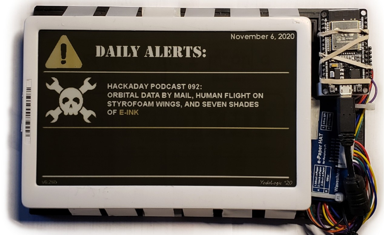
If you’ve recently braved the pandemic long enough to make a trip to a big box retailer, you may have spotted a few massive e-paper price tags affixed to large items like appliances. These seven inch displays were likely designed to be used in e-readers such as the Kindle, but through some surplus deal, are now shouting out clearance savings on last year’s washing machine. After checking out a particularly good price for a Samsung refrigerator at the local Home Depot, [YodaLogic] got to wondering if they could be bent to the hacker’s will.

Now to be clear, [YodaLogic] didn’t steal any of these tags. It turns out you can pick them up on eBay for less than $15 a pop, or at least that’s what they cost before this article went out. It’s an exceptionally good price when you realize that these displays are actually capable of color…albeit only two. Apparently when the retailer orders the so-called “Chroma 74” tags, they can pick between either yellow or red as the secondary color. While not quite as exciting as a full-color display, it certainly sets them apart from most of the e-paper panels we’ve seen used in DIY projects thus far.

The panel gets mighty close to the HaD color scheme

We’d like to tell you that [YodaLogic] cracked one of these things open and was able to wire it right up to a Pi or microcontroller, but the truth is a bit more complicated. Connecting the Chroma 74’s panel to the control board intended for a similar Waveshare 7.5 inch display didn’t seem to do anything. After some poking and prodding, it became clear that the WFD0750BF19 e-paper panel used in the Chroma needed a custom software profile to bring it to life. Unfortunately, there doesn’t seem to be a datasheet available for this particular panel.

By combining what could be gleaned from the datasheets of similar displays with a bit of experimentation, [YodaLogic] came up with a configuration profile that mostly works. It doesn’t seem like the yellow is as vibrant as it should be, and a refresh can take as long as 20 seconds, but it’s certainly a start. Perhaps the code can be tightened up with some input from the community, or even better, maybe somebody out there knows where we can get our hands on the datasheet for this panel.

While we’ve started to see more projects use e-paper displays, their high price still keeps many hackers away. Being able to repurpose cheap hardware like this could really spur some interesting development, so we’re excited to see [YodaLogic] put the finishing touches on this project and opened it up to a wider audience.

source https://hackaday.com/2020/11/27/repurposing-large-electronic-price-tags/

So Close to Landing a Model Rocket on Its Tail

We’ve become so used to seeing SpaceX boosters land themselves back on the pad with clockwork reliability, that it’s easy to forget it took them a good number of attempts to get right. Inspired by SpaceX’s work, [Joe Barnard] of [BPS.Space] started working to replicate it at the model scale five years ago, with no engineering education or experience. On the latest attempt with a brand-new thrust vectoring Scout E rocket, he has gotten tantalizingly close to doing a controlled propulsive landing with a solid-fuel rocket motor.

We’ve all been thrilled to see the SpaceX rockets return to earth, landing elegantly on a floating pad. But those are liquid-fueled. The trick with a solid-fuel rocket motor is it can’t be throttled directly, which is a challenge when you need precision control to land. Thanks to [Joe]’s custom AVA flight computer and the remarkably consistent thrust curve of the Estes F15 black powder motors he used, it becomes a matter of igniting the descent motor at the right moment to make the vertical velocity zero at touchdown. However, [Joe] found that the time between sending the ignition signal and when peak thrust is reached was inconsistent, so he had to work around that. He did this by controlling how much of the thrust is spent in the vertical direction, by vectoring the motor side to side to spend some trust horizontally.

View from rocket of the ascent motor falling away immediately after being ejected

In this attempt, the rocket tipped over on landing due to excessive horizontal movement at touchdown. Joe tracked the cause down to a weak GPS signal caused by antenna position and a possible bug in the Kalman filter that fuses all the sensor data for position and velocity estimation. Thanks to incredibly detailed telemetry and logging done by the flight computer, data from every launch are used for future improvements. We are looking forward to the next flight in a few weeks, during which [Joe] plans to tune and test the control software, among other minor improvements.

Almost every single part of this rocket is a display of engineering ingenuity. The landing struts are designed to absorb as much impact as possible without bouncing while being light and quick to deploy. The ascent motor is ejected simply by moving the thrust vectoring mount to one of its extremes, allowing the descent motor to drop into place. The rocket also features a complete emergency abort system with a parachute, which can be activated manually, or by the flight computer if it calculates that landing isn’t feasible. We already covered [Joe]’s latest launch pad, which is a very interesting project all by itself.

source https://hackaday.com/2020/11/27/so-close-to-landing-a-model-rocket-on-its-tail/

So Close to Landing a Model Rocket on Its Tail

We’ve become so used to seeing SpaceX boosters land themselves back on the pad with clockwork reliability, that it’s easy to forget it took them a good number of attempts to get right. Inspired by SpaceX’s work, [Joe Barnard] of [BPS.Space] started working to replicate it at the model scale five years ago, with no engineering education or experience. On the latest attempt with a brand-new thrust vectoring Scout E rocket, he has gotten tantalizingly close to doing a controlled propulsive landing with a solid-fuel rocket motor.

We’ve all been thrilled to see the SpaceX rockets return to earth, landing elegantly on a floating pad. But those are liquid-fueled. The trick with a solid-fuel rocket motor is it can’t be throttled directly, which is a challenge when you need precision control to land. Thanks to [Joe]’s custom AVA flight computer and the remarkably consistent thrust curve of the Estes F15 black powder motors he used, it becomes a matter of igniting the descent motor at the right moment to make the vertical velocity zero at touchdown. However, [Joe] found that the time between sending the ignition signal and when peak thrust is reached was inconsistent, so he had to work around that. He did this by controlling how much of the thrust is spent in the vertical direction, by vectoring the motor side to side to spend some trust horizontally.

View from rocket of the ascent motor falling away immediately after being ejected

In this attempt, the rocket tipped over on landing due to excessive horizontal movement at touchdown. Joe tracked the cause down to a weak GPS signal caused by antenna position and a possible bug in the Kalman filter that fuses all the sensor data for position and velocity estimation. Thanks to incredibly detailed telemetry and logging done by the flight computer, data from every launch are used for future improvements. We are looking forward to the next flight in a few weeks, during which [Joe] plans to tune and test the control software, among other minor improvements.

Almost every single part of this rocket is a display of engineering ingenuity. The landing struts are designed to absorb as much impact as possible without bouncing while being light and quick to deploy. The ascent motor is ejected simply by moving the thrust vectoring mount to one of its extremes, allowing the descent motor to drop into place. The rocket also features a complete emergency abort system with a parachute, which can be activated manually, or by the flight computer if it calculates that landing isn’t feasible. We already covered [Joe]’s latest launch pad, which is a very interesting project all by itself.

source https://hackaday.com/2020/11/27/so-close-to-landing-a-model-rocket-on-its-tail/