Shhh… Robot Vacuum Lidar is Listening

There are millions of IoT devices out there in the wild and though not conventional computers, they can be hacked by alternative methods. From firmware hacks to social engineering, there are tons of ways to break into these little devices. Now, researchers at University of Maryland have published a new hack to allows audio capture using lidar reflective measurements.

The hack revolves around the fact that audio waves or mechanical waves in a room cause objects inside a room to vibrate slightly. When a lidar device impacts a beam off an object, the accuracy of the receiving system allows for measurement of the slight vibrations cause by the sound in the room. The experiment used human voice transmitted from a simple speaker as well as a sound bar and the surface for reflections were common household items such as a trash can, cardboard box, takeout container, and polypropylene bags. Robot vacuum cleaners will usually be facing such objects on a day to day basis.

The bigger issue is writing the filtering algorithm that is able to extract the relevant information and separate the noise, and this is where the bulk of the research paper is focused (PDF). Current developments in Deep Learning assist in making the hack easier to implement. Commercial lidar is designed for mapping, and therefore optimized for reflecting off of non-reflective surface. This is the opposite of what you want for laser microphone which usually targets a reflective surface like a window to pick up latent vibrations from sound inside of a room.

Deep Learning algorithms are employed to get around this shortfall, identifying speech as well as audio sequences despite the sensor itself being less than ideal, and the team reports achieving an accuracy of 90%. This lidar based spying is even possible when the robot in question is docked since the system can be configured to turn on specific sensors, but the exploit depends on the ability to alter the firmware, something the team accomplished using the Dustcloud exploit which was presented at DEF CON in 2018.

You don’t need to tear down a Roomba for this experiment since there are a lot of lidar-based rovers out there. We’ve even seen open source lidar sensors that are even better for experimental purposes.

Thanks for the tip [Qes]

source https://hackaday.com/2020/11/27/shhh-robot-vacuum-lidar-is-listening/

Chess Computer Retires to Play Jazz

Years ago, [Leo Neumann]’s girlfriend gave him a 1970s chess computer game that was missing almost everything but the super cool clicky keyboard. Noting the similarity of chess move labeling to chord notation, [Leo] decided to turn it into something even nerdier — a jazz chord game where you jam with the computer.

To play the game, you and the computer take turns entering jazz chords that progress musically from the last one played. The hardware is simple — a Raspberry Pi Zero and a WM8960 audio hat with amplifier in speakers. [Leo] also put in a slightly larger display than the original and printed a new bottom half for the case. We love the look of this build, especially the groovy custom line font [Leo] designed.

On the software side, [Leo] made a Python prototyping environment using PYO Module and Kivy UI. Not content with other approaches to tonal consonance, [Leo] played a couple thousand chords and rated them according to their progressive harmony. Shake out those jazz hands and check it out after the break.

Want to play chess with computers? Make Alexa your go-between.

source https://hackaday.com/2020/11/26/chess-computer-retires-to-play-jazz/

TinyTacho: Rotational Speed Measurement Without The Bulk

An electronic tachometer is a straightforward enough device, in which the light reflections from a white spot on a rotating object are detected and counted over time, measuring the revolutions per minute (RPM). It’s a technique that has its roots in analogue electronics where the resulting pulses would have fed a charge pump, and it’s a task well suited to a microcontroller that simply counts them. But do you need an all-singing, all-dancing chip to do the job? [Stefan Wagner] has done it with a humble ATtiny13.

His TinyTacho is a small PCB with an IR LED and photodiode on one end, a small OLED display on its front, and a coin cell holder on its rear. The electronics may be extremely simple, but there’s still quite some effort to get it within the ATtiny’s meagre resources. Counting the revolutions is easy enough, but the chip has no I2C interface of its own and some bitbanging code is required. You can find all the design files and software you need in a GitHub repository, and he’s put up a video of the device in action that you can see below the break.

Tachometers are a popular project hereabouts, and we’ve featured a lot of them over the years. Perhaps the best place to direct readers then is not to another project, but to how to use a tachometer.

source https://hackaday.com/2020/11/26/tinytacho-rotational-speed-measurement-without-the-bulk/

Building a Workshop Crane From Scratch

Buying tools is all well and good, but it doesn’t suit the ethos of Youtube channel [Workshop From Scratch]. Building what you need is much more the go, and that’s demonstrated ably with this home-built electric workshop crane.

The crane is put together in a straightforward manner using basic steelworking techniques. Plates and bars are machined with a drill press, bandsaw and grinder, though we could imagine you could use hand tools if you were so inclined. An ATV winch is pressed into service to do the heavy lifting, powered by a set of 12V lead acid batteries placed in the base. This design choice does double duty as both a mobile power supply for the crane, and acts as a counterweight in the base.

The final result looks sharp in its orange paint finish, and does a good job of moving heavy equipment around the workshop. The legs are reconfigurable, so that even very heavy loads can be lifted with appropriate counterweight placed on the back. It’s a significant upgrade on the earlier version we featured last year, which was hydraulic in operation. Video after the break.

source https://hackaday.com/2020/11/26/building-a-workshop-crane-from-scratch/

Alfa Romeo Gauge Cluster Gets a Fresh Set of LEDs

On older vehicles, if you noticed that the lights had gone out behind one of your gauges, you knew it was time to snake your hand back there and replace the little incandescent bulb that had given up the ghost. But what are you supposed to do if you’re seeing the same problem on a modern vehicle that’s already made the leap to LED dash lighting? That’s what [Tysonpower] recently had to find out when the fuel indicator on his Alfa Romeo Giuletta QV went dark.

In the video after the break, [Tysonpower] details how to remove the instrument cluster from the Giuletta’s dash, which we imagine would be a useful little tutorial for anyone who owns the same vehicle. Once he has it out on the bench, he strips it down to the bare PCB and starts (literally) poking around.

He eventually noticed that if he pushed on the board near the fuel indicator he could get the appropriate 3528 SMD LED to light up, but touching up the solder joints didn’t seem to fix the issue. Assuming the LED must be defective internally, he simply replaced it and all was good again.

Well, not exactly. The light produced by the new part didn’t match the color or brightness of the other dozen or so white LEDs that were installed on the board, so [Tysonpower] decided to just dive in and replace them all. While it obviously took a lot more time and effort, he says the end result is that the instrument cluster looks noticeably brighter and crisper when driving at night. Not bad for an afternoon’s work and a couple bucks worth of LEDs.

Most of the time, when we see somebody messing around behind the dash it’s because they intend on replacing the original instruments with something more capable. But projects like this, which add just a touch of refinement to the existing hardware, prove that stock components aren’t always a disappointment.

source https://hackaday.com/2020/11/26/alfa-romeo-gauge-cluster-gets-a-fresh-set-of-leds/

Alfa Romeo Gauge Cluster Gets a Fresh Set of LEDs

On older vehicles, if you noticed that the lights had gone out behind one of your gauges, you knew it was time to snake your hand back there and replace the little incandescent bulb that had given up the ghost. But what are you supposed to do if you’re seeing the same problem on a modern vehicle that’s already made the leap to LED dash lighting? That’s what [Tysonpower] recently had to find out when the fuel indicator on his Alfa Romeo Giuletta QV went dark.

In the video after the break, [Tysonpower] details how to remove the instrument cluster from the Giuletta’s dash, which we imagine would be a useful little tutorial for anyone who owns the same vehicle. Once he has it out on the bench, he strips it down to the bare PCB and starts (literally) poking around.

He eventually noticed that if he pushed on the board near the fuel indicator he could get the appropriate 3528 SMD LED to light up, but touching up the solder joints didn’t seem to fix the issue. Assuming the LED must be defective internally, he simply replaced it and all was good again.

Well, not exactly. The light produced by the new part didn’t match the color or brightness of the other dozen or so white LEDs that were installed on the board, so [Tysonpower] decided to just dive in and replace them all. While it obviously took a lot more time and effort, he says the end result is that the instrument cluster looks noticeably brighter and crisper when driving at night. Not bad for an afternoon’s work and a couple bucks worth of LEDs.

Most of the time, when we see somebody messing around behind the dash it’s because they intend on replacing the original instruments with something more capable. But projects like this, which add just a touch of refinement to the existing hardware, prove that stock components aren’t always a disappointment.

source https://hackaday.com/2020/11/26/alfa-romeo-gauge-cluster-gets-a-fresh-set-of-leds/

Alfa Romeo Gauge Cluster Gets a Fresh Set of LEDs

On older vehicles, if you noticed that the lights had gone out behind one of your gauges, you knew it was time to snake your hand back there and replace the little incandescent bulb that had given up the ghost. But what are you supposed to do if you’re seeing the same problem on a modern vehicle that’s already made the leap to LED dash lighting? That’s what [Tysonpower] recently had to find out when the fuel indicator on his Alfa Romeo Giuletta QV went dark.

In the video after the break, [Tysonpower] details how to remove the instrument cluster from the Giuletta’s dash, which we imagine would be a useful little tutorial for anyone who owns the same vehicle. Once he has it out on the bench, he strips it down to the bare PCB and starts (literally) poking around.

He eventually noticed that if he pushed on the board near the fuel indicator he could get the appropriate 3528 SMD LED to light up, but touching up the solder joints didn’t seem to fix the issue. Assuming the LED must be defective internally, he simply replaced it and all was good again.

Well, not exactly. The light produced by the new part didn’t match the color or brightness of the other dozen or so white LEDs that were installed on the board, so [Tysonpower] decided to just dive in and replace them all. While it obviously took a lot more time and effort, he says the end result is that the instrument cluster looks noticeably brighter and crisper when driving at night. Not bad for an afternoon’s work and a couple bucks worth of LEDs.

Most of the time, when we see somebody messing around behind the dash it’s because they intend on replacing the original instruments with something more capable. But projects like this, which add just a touch of refinement to the existing hardware, prove that stock components aren’t always a disappointment.

source https://hackaday.com/2020/11/26/alfa-romeo-gauge-cluster-gets-a-fresh-set-of-leds/

Tiny Ethernet Routers Now Available In Gigabit Speeds

If you need to move a lot of data, and fast, Gigabit Ethernet is a great way to do it. However, most network hardware outside of datacenters is fairly space inefficient, a headache if you’re building a robot or drone. Enter the Gigablox, a super-compact Gigabit router for just these applications.

The Gigablox takes its mission seriously, with its compact size the ultimate design goal. The entire switch fits on a tiny 45 mm x 45 mm PCB. To this end, it eschews the common RJ45 connector, which is bulkier than necessary. Instead, thin Molex PicoBlade connectors are used for the five ports on board. Cables are included to convert between the two connectors, and obviously crimping ones own is easy to do, too. For those who need to connect more devices, several Gigablox can be hooked up in the same way as any other Ethernet switch. The Gigablox is a non-blocking switch, too – meaning all five ports can run at full speed simultaneously.

The design is the sequel to the SwitchBlox, and the later SwitchBlox Nano, both designed by [Josh Elijah] earlier this year. The pace of development is impressive, and it’s great to see [Josh] bring Gigabit speeds to the compact form factor. We can imagine a few good uses for these boards; share your best ideas in the comments below! Video after the break.

source https://hackaday.com/2020/11/26/tiny-ethernet-routers-now-available-in-gigabit-speeds/

Cornhole Boards Play Victory Songs

How do you instantly make any game better? By lighting it up and playing at night. We would normally say ‘drinking’, but we’re pretty sure that drinking is already a prerequisite for cornhole — that’s the game where you toss bean bags at holes in angled boards.

[Hardware Unknown] loves cornhole, and was gifted a set of portable, folding boards that light up around the ring for nighttime action. These turned out to be the perfect basis for reactive boards that light up and play sound whenever points are scored. Both boards have a vibration sensor to detect bags hitting the top, and an IR break-beam sensor pair across the hole. An Arduino Nano reads from the sensors and controls an amplifier and a DF Player for sound.

Players get a point and a song for landing a bag on top of the board, and three points and a different song for making it in the hole. We love the Easter egg — anyone who manages to trip both the vibration sensor and the break-beam detector at the same time will be treated to the sound of a flock of honking geese. Check out the build journey after the break.

No good at cornhole? This one doesn’t let you miss.

source https://hackaday.com/2020/11/26/cornhole-boards-play-victory-songs/

Electric BMX with Friction Drive

Electric bikes have increased in popularity dramatically over the past few years, and while you can easily buy one from a reputable bicycle manufacturer, most of us around here might be inclined to at least buy a kit and strap it to a bike we already have. There aren’t kits available for every bike geometry, though, so if you want an electric BMX bike you might want to try out something custom like [Shea Nyquist] did with his latest build. (Video, embedded below.)

BMX frames have a smaller front triangle than most bikes, so his build needed to be extremely compact. To that end, it uses two small-sized motors connected together with a belt, which together power a friction drive which clamps against the rear tire to spin it directly. This keeps the weight distribution of the bike more balanced as well when compared to a hub drive, where the motor is installed in the rear wheel. It also uses a more compact lithium polymer battery pack instead of the typical 18650 lithium ion packs most e-bikes use, and although it only has a range of around three miles it’s more than enough charge to propel it around a skate park.

The build boasts impressive numbers too, at 2.5 kW peak power per motor. This puts it in electric motorcycle territory, and it’s indeed fast despite its small stature. For a true high speed e-bike experience, though, you’ll need a slightly larger frame and motor even if it means tossing safety out of the window.

source https://hackaday.com/2020/11/26/electric-bmx-with-friction-drive/

Adding USB To A Keyboard The Way It Used To Be Done

The world of custom keyboards has over the years developed its work into an art form, as mechanical key switches meet USB-HID capable microcontrollers for a plethora of designs as individual as their creators. This was however not always the case, and from the days of 8-bit home computers onwards making a custom keyboard often meant taking a surplus one from elsewhere and adapting its matrix to suit whatever controller interface was at hand. [Julian Calaby]’s USB conversion of an Apple Extended keyboard may be unusual in this day and age and was probably a late example even 15 years ago when he made it, but it remains a glorious piece of bodge-wire hardware hacking at its finest.

The task at hand with this type of conversion is to cut the matrix PCB tracks and replace them with soldered wires to create the new matrix required. This can then be wired to the controller, which in [Julian]’s case came from a cheap USB keyboard. He added a small USB hub to allow for a pair of USB sockets where Apple had put an ADB socket, making for quite a decent older keyboard with an unexpected USB interface.

Now older and wiser, he has plans to revisit his old keyboard with a modern microcontroller board, and needs to revisit the matrix again and give the peripheral new life. We still like the original though, as it captures a moment in time when keyboard matrix hacking made sense, and reminds us of our own youthful hardware follies.

Paging through Hackaday past it’s a testament to the old-school nature of this board that all we can find are microcontroller-based conversions. That’s not to say that cutting up old ‘boards is out of the question though.

source https://hackaday.com/2020/11/26/adding-usb-to-a-keyboard-the-way-it-used-to-be-done/

Zoombombing the EU Foreign Affairs Council

Those with security clearance are capable of making foolish mistakes, just like the rest of us. So is the story of how a Dutch journalist made an appearance on video meeting of the European Union’s Foreign Affairs Council (Dutch language, Google Translate link).

Ank Bijleveld's Tweeted picture, with the access details blacked out by Daniël Verlaan.
Netherlands Defence MInister Ank Bijleveld’s Tweeted picture, with the access details blacked out by Daniël Verlaan.

Like any other video call, if you had the link you could enter the meeting. So when Netherlands Defence Minister Ank Bijleveld Tweeted a photo of a video call last Friday, the address bar of the browser gave away the secret to anyone with a keen eye. Dutch journalist Daniël Verlaan working for the broadcaster RTL saw the URL on the screen and deduced the login credentials for the meeting.

We say “deduced”, but in fact there were five of the six digits in the PIN in the clear in the URL, leaving him with the difficult task of performing a one-digit brute-force attack and joining with the username “admin”. He joined and revealed his presence, then was admonished for committing a criminal offence before he left.

On one level it’s an opportunity for a good laugh at the expense of the defence ministers, and we certainly wouldn’t want to be Ank Bijleveld or probably the EU’s online security people once the inevitable investigation into this gets under way. It seems scarcely credible that the secrecy on such a high-security meeting could have sat upon such a shaky foundation without for example some form of two-factor authentication using the kind of hardware available only to governments.

EU policy is decided not by individual ministries but by delicate round-table summits of all 27 countries. In a pandemic these have shifted to being half-online and half in-real-life, so this EU defence ministers’ meeting had the usual mosaic video feed of politicians and national flags. And one Zoom-bombing journalist.

source https://hackaday.com/2020/11/25/zoombombing-the-eu-foreign-affairs-council/

Cleaner Laser Cutting With a 3D-Printed Nozzle

[Nervous System] does a lot of laser cutting, and [Jesse] shared a fascinating experimental improvement to their laser cutter that consists of a 3D-printed nozzle for cleaner cuts. You can see the results for yourself above, where the difference between the two cuts is striking.

[Jesse]’s modification doesn’t affect the laser beam itself; it is an improvement on the air assist, which is the name for a constant stream of air that blows away smoke and debris as the laser burns and vaporizes material. An efficient air assist is one of the keys to getting nice clean laser cuts, but [Jesse] points out that a good quality air assist isn’t just about how hard the air blows, it’s also about how smoothly it does so. A turbulent air assist can make scorch marks worse, not better.

3D-printed nozzle to promote laminar air flow on the left, stock nozzle on the right.

As an experiment to improve the quality of the air flowing out the laser nozzle, [Jesse] researched ways to avoid turbulence by creating laminar flow. Laminar flow is the quality of a liquid having layers flowing past one another with little or no mixing. One way to do this is to force liquid through individual, parallel channels as it progresses towards a sharply-defined exit nozzle. While [Jesse] found no reference designs of laminar flow nozzles for air assists, there were definitely resources on making laminar flow nozzles for water. It turns out that interest in such a nozzle exists mainly as a means of modifying Lonnie Johnson’s brilliant invention, the Super Soaker.

Working from such a design, [Jesse] created a custom nozzle to help promote laminar flow. Sadly, a laser cutter head carries design constraints that make some compromises unavoidable; one is limited space, and another is the need to keep the laser’s path unobstructed. Still, after 3D printing it in rigid heat-resistant resin, [Jesse] found a dramatic improvement in the feel of the air exiting the nozzle. Some test cuts confirmed a difference in performance, which results in a noticeably cleaner kerf without scorching around the edges.

One of the things [Nervous System] does is make their own custom puzzles, so any improvement to laser cutting helps reliability and quality. When production is involved, just about everything matters; a lesson [Nervous System] shared when they discussed making the best plywood for creating their puzzles.

source https://hackaday.com/2020/11/25/cleaner-laser-cutting-with-a-3d-printed-nozzle/

Literally Tearing Apart a SpaceX Starlink Antenna

While SpaceX’s constellation of Starlink satellites is nowhere near its projected final size, the company has enough of the birds zipping around in low Earth orbit to start a limited testing period they call the Better Than Nothing Beta. If you’re lucky enough to get selected, you have to cough up $500 for the hardware and another $100 a month for the service. Despite the fairly high bar for getting your hands on one, [Kenneth Keiter] decided to sacrifice his Starlink dish to the teardown Gods.

We say sacrifice because [Kenneth] had to literally destroy the dish to get a look inside. It doesn’t appear that you can realistically get into the exceptionally thin antenna array without pulling it all apart, thanks in part to preposterous amount of adhesive that holds the structural back plate onto the PCB. The sky-facing side of the phased array, the key element that allows the antenna to track the rapidly moving Starlink satellites as they pass overhead, is also laminated to a stack-up comprised of plastic hexagonal mesh layers, passive antenna elements, and the outer fiberglass skin. In short, there are definitely no user-serviceable parts inside.

The dish hides many secrets under its skin.

Beyond attempting to analyze the RF magic that’s happening inside the antenna, [Kenneth] also takes viewers through a tour of some of the more recognizable components of the PCB; picking out things like the Power over Ethernet magnetics, a GPS receiver, some flash storage, and the H-Bridge drivers used to control the pan and tilt motors in the base of the dish.

It also appears that the antenna is a self-contained computer of sorts, complete with ARM processor and RAM to run the software that aims the phased array. Speaking of which, it should come as no surprise to find that not only are the ICs that drive the dizzying array of antenna elements the most numerous components on the PCB, but that they appear to be some kind of custom silicon designed specifically for SpaceX.

In short, there’s still plenty we don’t know about how this high-tech receiver actually works. While [Kenneth] does a respectable job of trying to make sense of it all, and we respect his dedication to rip apart such a rare and expensive piece of kit, it’s still going to be awhile before the hacker community truly masters the tech that SpaceX is putting into their ambitions global Internet service.

[Thanks to Alex for the tip.]

source https://hackaday.com/2020/11/25/literally-tearing-apart-a-spacex-starlink-antenna/

Literally Tearing Apart a SpaceX Starlink Antenna

While SpaceX’s constellation of Starlink satellites is nowhere near its projected final size, the company has enough of the birds zipping around in low Earth orbit to start a limited testing period they call the Better Than Nothing Beta. If you’re lucky enough to get selected, you have to cough up $500 for the hardware and another $100 a month for the service. Despite the fairly high bar for getting your hands on one, [Kenneth Keiter] decided to sacrifice his Starlink dish to the teardown Gods.

We say sacrifice because [Kenneth] had to literally destroy the dish to get a look inside. It doesn’t appear that you can realistically get into the exceptionally thin antenna array without pulling it all apart, thanks in part to preposterous amount of adhesive that holds the structural back plate onto the PCB. The sky-facing side of the phased array, the key element that allows the antenna to track the rapidly moving Starlink satellites as they pass overhead, is also laminated to a stack-up comprised of plastic hexagonal mesh layers, passive antenna elements, and the outer fiberglass skin. In short, there are definitely no user-serviceable parts inside.

The dish hides many secrets under its skin.

Beyond attempting to analyze the RF magic that’s happening inside the antenna, [Kenneth] also takes viewers through a tour of some of the more recognizable components of the PCB; picking out things like the Power over Ethernet magnetics, a GPS receiver, some flash storage, and the H-Bridge drivers used to control the pan and tilt motors in the base of the dish.

It also appears that the antenna is a self-contained computer of sorts, complete with ARM processor and RAM to run the software that aims the phased array. Speaking of which, it should come as no surprise to find that not only are the ICs that drive the dizzying array of antenna elements the most numerous components on the PCB, but that they appear to be some kind of custom silicon designed specifically for SpaceX.

In short, there’s still plenty we don’t know about how this high-tech receiver actually works. While [Kenneth] does a respectable job of trying to make sense of it all, and we respect his dedication to rip apart such a rare and expensive piece of kit, it’s still going to be awhile before the hacker community truly masters the tech that SpaceX is putting into their ambitions global Internet service.

[Thanks to Alex for the tip.]

source https://hackaday.com/2020/11/25/literally-tearing-apart-a-spacex-starlink-antenna/

TV Head Is Great Replacement For Your Real Head

The head is one of the few parts of the body that it seems impossible to live without. Many people are, of course, not happy with the one they’ve been given. For those dreaming of a more digital replacement, [Vivian’s] TV Head might be just the accessory to meet those needs.

The build starts with an old CRT, which [Vivian] promptly gutted to make room for her head. In place of the original tube, a thin polycarbonate sheet was installed with window tint applied. Behind this, rows of WS2812B are set up in a grid, spaced apart just enough to allow the wearer to see through.  The setup is controlled by a Circuit Playground Express. A small PS/2 keyboard is used to control the light show, and the onboard accelerometer can be used for gravity reactive animations.

For some reason, screens as heads are remarkably emotive, and we kind of want one for daily wear. We can imagine it making a great Halloween costume, too. If you’ve always wanted to cosplay as one of those colorful robots from the Opening Ceremony of the 2002 World Cup, here’s your chance. You will not be surprised that this isn’t the first TV head we’ve featured. Video after the break.

source https://hackaday.com/2020/11/25/tv-head-is-great-replacement-for-your-real-head/

A Raspberry Pi 400 UPS Add-On, It’s Not All Plain Sailing

Since the recent launch of the all-in-one Raspberry Pi 400, the global hardware community have taken to the new platform and are investigating its potential for hardware enhancements. On the back it has the same 40-pin expansion connector as its single-board siblings, but it’s horizontal rather than vertical, which means that all of the conventional HATs sit in a rather ungainly upright position.

One of the first Pi 400 HATs we’ve seen comes from [Patrick Van Oosterwijck], who has made a very neat 18650-based UPS add-on that is intended to eventually fit in the back of the machine in a similar way to the home computer cartridge peripherals of old. Unfortunately not all has gone according to plan, and in finding out why that is the case we learn something about the design of the 400, and maybe even take a chance to reflect on the Pi Foundation itself.

On the face of it the 400’s interface is the same as that of its single board computer stablemates, but something this project reveals is that its 5 V pins have a current limit of 1 A. This turns out to preclude the type of plug-in Pi UPS that sits on a HAT that we’re used to, in that 1 A through the 5 V pin is no longer enough to run the computer.

This effectively puts a stop to [Patrick]’s project, though he can repurpose it for a Pi 4 and its siblings once he’s dealt with a converter chip overheating problem. He does however make a complaint about the Pi Foundation’s slowness in releasing such data about their products, and given that long-time Pi-watchers will remember a few other blips in the supply of Pi hardware data he has a point. A quick check of the Raspberry Pi GitHub repository reveals nothing related to the Pi 400 at the time of writing, and though it shares much with its Pi 4 sibling it’s obvious that there are enough differences to warrant some extra information.

Hardware hackers may not be part of the core education focus of the Pi range, but a healthy, interested, and active hardware community that feels nurtured by its manufacturer remains key to the supply of interesting Pi-related products feeding into that market. We’d like to urge the Pi Foundation to never forget the hardware side of their ecosystem, and make hardware specification an integral part of every product launch on day one.

If the Pi 400 catches your interest, you can read our review here.

source https://hackaday.com/2020/11/25/a-raspberry-pi-400-ups-add-on-its-not-all-plain-sailing/

SMD Challenge Extreme Edition Gets Our Flux Flowing

Skills challenges have become a fun way to facilitate friendly competition amongst anyone who appreciates a fine solder joint. If you’ve seen any Supercon / Remoticon coverage there’s surely been a mention of the infamous soldering skills challenge, where competitors test their mettle against surface mount components sized to be challenging but fair. What if there was a less friendly SMD challenge designed to make you hold your breath lest you blow the components away? Well now there is, the SMD Challenge Extreme Edition by friend-of-the-Hackaday and winner of the 2019 Supercon soldering challenge [Freddie].

When assembled the SMD Extreme Edition uses a 555 timer and a 74HC4017 decade counter to light a ring of 10 LEDs lights around its perimeter, powered by a coin cell. However the  Extreme Edition deviates from the typical SMD Challenge format. Instead of ramping up in difficulty with ever-shrinking components, the Extreme Edition only has one size: torturous. See those gray blobs in the title image? Those are grains of rice.

The Extreme Edition’s 0201-sized LEDs aren’t the absolute smallest components around, but to minimize enjoyment all passives are 01005. (Check out the SMD Challange Misery Edition for even 01005 LED action.)

The Extreme Edition has other tricks up its sleeve, too. That 555 may be venerable in age, but this version is in an iron-frustrating 1.41 x 1.43 mm BGA package, which pairs nicely with that decade counter in 2.5 mm x 3.5 mm QFN.

Despite the wordwide pandemic locking down travel and conferences, a few brave challengers have already taken up their iron and succeeded at Extreme SMD. Want to see it in action? Check out the original Tweets after the break.


source https://hackaday.com/2020/11/25/smd-challenge-extreme-edition-gets-our-flux-flowing/

True Networked KVM Without Breaking the Bank

For administering many computers at once, an IP KVM is an invaluable piece of equipment that makes it possible to get the job done over the network without having to haul a keyboard, monitor, and mouse around to each computer. The only downside is that they can get pricey, unless of course you can roll one out based on the Raspberry Pi and the PiKVM image for little more than the cost of the Pi itself.

The video linked below shows how to set all of this up, which involves flashing the image and then setting up the necessary hardware. The build shows an option for using HDMI over USB, but another option using the CSI bus would allow for control over options like video resolution and color that a USB HDMI dongle doesn’t allow for. It also makes it possible to restart the computer and do things like configure BIOS or boot from removable media, which is something that would be impossible with a remote desktop solution like VNC.

The creator of PiKVM was mentioned in a previous post about the creation of the CSI bus capture card, and a Pi hat based on this build will be available soon which would include options for ATX controls as well. Right now, though, it’s possible to build all of this on your own without the hat, and is part of what makes the Pi-KVM impressive, as well as its very low cost.

source https://hackaday.com/2020/11/24/true-networked-kvm-without-breaking-the-bank/

Real Spectrum Analysis Goes Virtual

One of the hard things about electronics is that you can’t really see the working parts without some sort of tool. If you work on car engines, fashion swords, or sculpt clay, you can see with your unaided eye what’s going on. Electronic components are just abstract pieces and the real action requires a meter or oscilloscope to understand. Maybe that’s what [José] was thinking of when he built a-radio. This “humble experiment” pipes a scan from a software-defined radio into VR goggles, which can be as simple as a smartphone and some cardboard glasses.

The resulting image shows you what the radio spectrum looks like. Granted, so will a spectrum analyzer, but perhaps the immersion will provide a different kind of insight into radio frequency analysis.

[José] admits the project is the result of a “boring morning” so there is probably some room for improvement. We wondered if an array of antennas could give you head tracking so you could see what direction a signal was coming from, or — at least — where it was strongest.

Is this really better than just staring at a waterfall display? Perhaps not. But it is still a novel approach and we have to wonder if it couldn’t be used for other things? Maybe a VR circuit simulator or visualizing antenna patterns, for example.

A spectrum analyzer used to be a big purchase, but not anymore. For that matter, VR headgear used to be a big deal, too.

source https://hackaday.com/2020/11/24/real-spectrum-analysis-goes-virtual/

DIY Camera Motion Rig Is Mostly 3D Printed

These days, Youtube is more competitive than ever. Creators put out videos of wildly expensive, complex projects with equally pricy camera gear. [Do It Whenever?] wanted to join the arms race, building his own camera rig for smooth, swooping shots.

The rig consists of a series of 3D printed axes all joined together into a 6-axis motion rig. Additionally, actuators attached to the lens of the camera allow zoom and focus to be be controlled programmatically too. An Arduino runs the show, interpreting G-code and running the various axes, with a Raspberry Pi acting as a gateway to allow the rig to be commanded from PCs or smartphones.

Currently, control is largely manual, by entering G-code commands to move the rig in various ways. The rig can also have its motors temporarily disengaged by a button, allowing the camera to be aimed by hand, before holding the position. In this way, it acts as a highly versatile tripod. Future plans involve more automation if suitable open-source software can be found.

It’s an impressive rig, even if it hasn’t quite found the perfect software to fully exploit its capabilities yet. We’ve seen similar builds before, too. Video after the break.

[Thanks to Zane Atkins for the tip]

source https://hackaday.com/2020/11/24/diy-camera-motion-rig-is-mostly-3d-printed/

Digispark Spoofs IR To Get Speakers Under Control

The Microlab 6C are a pretty nice pair of speakers, but [Michał Słomkowski] wasn’t too thrilled with the 8 watts they consume when on standby. The easy fix is to just unplug them when they aren’t in use, but unfortunately the digital controls on the front panel mean he’s got to turn them on, select the correct input, and turn the volume up to the appropriate level every time they’re plugged back in. Surely there must be a better way.

His solution was to use a Digispark to fire off the appropriate IR remote codes so they’d automatically be put back into a usable configuration. But rather than putting an IR LED on one of the GPIO pins, he simply spliced it into the wire leading back from the speaker’s IR receiver. All his code needs to do is generate the appropriate pulses on the line, and the speaker’s electronics think its a signal coming in from the remote.

Distinctive patterns on the IR sensor wires.

Power for the Digispark is pulled from the speaker itself, so it turns on once [Michał] plugs them back in. The code waits five seconds to make sure the hardware has had time to start up, then proceeds with the “Power On”, “Change Input”, and “Volume Up” commands with a few seconds in between each for good measure.

Not only was it easier to skip the IR and inject the signals directly, but it also made for a cleaner installation. Since the microcontroller doesn’t need line of sight to the IR receiver, [Michał] was able to hide it inside the speaker’s enclosure. From the outside, the modification is completely invisible.

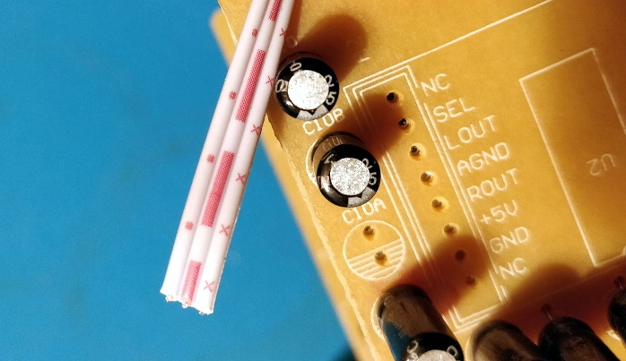
We’ve seen similar code injection tricks used before, and it’s definitely one of those techniques you should file away mentally for future reference. Even though more and more modern devices are embracing WiFi and Bluetooth control, the old school IR remote doesn’t seem like it’s going away anytime soon.

source https://hackaday.com/2020/11/24/digispark-spoofs-ir-to-get-speakers-under-control/

Bet You Didn’t Know Arduinos Are Psychic

Are you running out of ways to entertain yourself and your family? If you’ve read all the books and watched all the movies, it might be time to explore the psychic abilities of silicon. [Hari Wiguna] has just the trick to keep them guessing for a good long time.

This trick doesn’t take much, just a couple of Arduinos, some momentary buttons, a number pad, and a large helping of math. As you can see in the demo after the break, there is nothing connecting the two, not even 802.11(n). On the randomizer Arduino, [Hari] generates random numbers with the push of a button until the audience sees one they like. Then [Hari] locks in the number with the other button.

What happens next is key: the randomizer generates another random number, but uses it as a hint to set a sentinel digit. The randomizer Arduino subtracts the larger of the two digits in the number from nine and stores the result as the flag. When the next number comes up that has the flag digit in the correct place, the number after that will be the random number chosen at the beginning.

The psychic Arduino’s secret is that it knows the first guess it receives is special. It does the same sentinel digit math as the randomizer, so when the guesser enters the guess with the sentinel digit, it knows the next number entered is the winner. Clear as mud? Check out the second video below where [Hari] explains the trick, a new take on a magic classic.

Looking for a more exciting way to generate random numbers? Try using fish tanks, lava lamps, or muons from outer space.

source https://hackaday.com/2020/11/24/bet-you-didnt-know-arduinos-are-psychic/

Trashed Tablet Lives Again Thanks to New Charger IC

Have you ever pulled a piece of electronics from the trash that looked like nothing was wrong with it, only to take it home and find out it really is dead? Since you’re reading Hackaday, we already know the answer. Trash picking is an honored hacker tradition, and we all know it’s a gamble every time you pull something from the curb. But when the Samsung Galaxy Tab S that [Everett] pulled from the e-waste bin wouldn’t take a charge, he decided to crack it open and see if it was really beyond repair.

The first step was using a USB power meter to see if the tablet was actually pulling any current when plugged in. With just 10 mA on the line, [Everett] knew the device wasn’t even attempting to charge itself. So his next step was to pull the battery and charge it from a bench supply. This got the tablet to wake up, and as far as he could tell, everything else worked as expected. It seemed like the only issue was a blown charging circuit.

Where we’re going, we don’t need ribbon cables.

Now at this point, [Everett] could have just gone online and bought a new motherboard for the tablet and called it a day. But where’s the fun in that? Instead, he wired up a simple charging circuit using a TP4056 IC on a scrap of flexible PCB and mounted it to a square of Kapton tape. He then used 34 AWG magnet wire to connect it between the tablet’s USB port and the battery, bypassing the tablet’s electronics entirely.

The fix worked, but there was a slight problem. Since the TP4056 only goes up to 4.2 V and the battery maxes out at 4.35 V, [Everett] says his hacked charger can only bring the tablet up to 92% capacity according to Android. But considering the alternative, we think its more than a worthy trade-off.

It’s easy to dismiss tablets as largely disposable devices, but this isn’t the first time we’ve seen somebody save one with little more than solder and patience. Of course, what you do with that old tablet once you get it fired back up is another story entirely.

source https://hackaday.com/2020/11/24/trashed-tablet-lives-again-thanks-to-new-charger-ic/

Trashed Tablet Lives Again Thanks to New Charger IC

Have you ever pulled a piece of electronics from the trash that looked like nothing was wrong with it, only to take it home and find out it really is dead? Since you’re reading Hackaday, we already know the answer. Trash picking is an honored hacker tradition, and we all know it’s a gamble every time you pull something from the curb. But when the Samsung Galaxy Tab S that [Everett] pulled from the e-waste bin wouldn’t take a charge, he decided to crack it open and see if it was really beyond repair.

The first step was using a USB power meter to see if the tablet was actually pulling any current when plugged in. With just 10 mA on the line, [Everett] knew the device wasn’t even attempting to charge itself. So his next step was to pull the battery and charge it from a bench supply. This got the tablet to wake up, and as far as he could tell, everything else worked as expected. It seemed like the only issue was a blown charging circuit.

Where we’re going, we don’t need ribbon cables.

Now at this point, [Everett] could have just gone online and bought a new motherboard for the tablet and called it a day. But where’s the fun in that? Instead, he wired up a simple charging circuit using a TP4056 IC on a scrap of flexible PCB and mounted it to a square of Kapton tape. He then used 34 AWG magnet wire to connect it between the tablet’s USB port and the battery, bypassing the tablet’s electronics entirely.

The fix worked, but there was a slight problem. Since the TP4056 only goes up to 4.2 V and the battery maxes out at 4.35 V, [Everett] says his hacked charger can only bring the tablet up to 92% capacity according to Android. But considering the alternative, we think its more than a worthy trade-off.

It’s easy to dismiss tablets as largely disposable devices, but this isn’t the first time we’ve seen somebody save one with little more than solder and patience. Of course, what you do with that old tablet once you get it fired back up is another story entirely.

source https://hackaday.com/2020/11/24/trashed-tablet-lives-again-thanks-to-new-charger-ic/