
Youtube
My Balls – (Your Favorite Martian music video) #youtubevids
The TRUTH About Swallowing Gum | Responding To Comments #16 #youtubevids
Al Bundy’s Best Insults Reaction | DREAD DADS PODCAST | Rants, Reviews, Reactions #youtubevids
4 INCREDIBLE project with old CD/DVDrom #youtubevids
r/TalesFromRetail – Lady Сlaiming She Never Signed An Application To Run Her Credit. #youtubevids
Creative Craft DIY That Are At Another Level #youtubevids
Get Out Of My Head House!! | House M.D. #youtubevids
36 CUTE AND FUN RESIN AND CLAY DIYs TO MAKE IN 5 MINUTES #youtubevids
Marvel Studios’ Black Widow – Official Teaser Trailer #youtubevids
House MD – Funny Moments: Season 1 (HD) #youtubevids
My Wife Is My Sister?! | House M.D. #youtubevids
#TheMentalist 5.1 – What’s in your pocket? #youtubevids
#TheMentalist 2.01 – First Episode, First Scene #youtubevids
Modern Corner Shelf with Hidden Drawer and Secret Compartment #youtubevids
Funny Court Moments 1 #youtubevids
Just Another Accurate Diagnosis | House M.D. #youtubevids
[1 HOUR ] Gifs With Sound #5
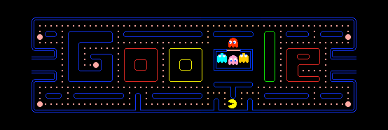
Pacman on Google
Did you know that if you search for “google pacman” you get a playable in-browser pacman game for desktop pc?
Give it a try
- May 21, 2010
- 30th Anniversary of PAC-MAN
- When I was growing up, my dad had the best job I could possibly imagine: he was an arcade game and pinball technician. For me, that meant summer trips through Poland’s coastal cities with their seasonal arcade parlors; peeking inside cabinets to learn programming and engineering secrets; and—of course—free games!
One of my favorites was PAC-MAN, whose popularity transcended the geopolitical barriers of that time. During the heyday of space shooters, Tōru Iwatani’s creation stood out as one of the first video games aimed at a broader audience, with a cute story of pizza-shaped character gobbling dots in a maze, colorful (literally!) characters, friendly design, very little violence and everlasting fun.
Today, on PAC-MAN’s 30th birthday, you can rediscover some of your 8-bit memories—or meet PAC-MAN for the first time—through our first-ever playable Google doodle. To play the game, go to google.com during the next 48 hours (because it’s too cool to keep for just one day) and either press the “Insert Coin” button or just wait for a few seconds.
Google doodler Ryan Germick and I made sure to include PAC-MAN’s original game logic, graphics and sounds, bring back ghosts’ individual personalities, and even recreate original bugs from this 1980’s masterpiece. We also added a little easter egg: if you throw in another coin, Ms. PAC-MAN joins the party and you can play together with someone else (PAC-MAN is controlled with arrow keys or by clicking on the maze, Ms. PAC-MAN using the WASD keys).
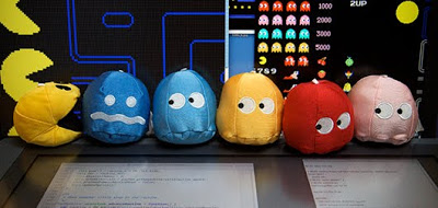
- PAC-MAN™ & ©1980 NAMCO BANDAI Games Inc.
PAC-MAN seems like a natural fit for the Google homepage. They’re both deceptively straightforward, carefully hiding their complexity under the hood. There’s a light-hearted, human touch to both of them. And we can only hope you find using Google at least a quarter as enjoyable as eating dots and chasing ghosts. You know, without actually needing any quarters.
Posted by Marcin Wichary, senior UX designer and developer

Jessica Nigri
BEST CUBE #46 #youtubevids
Tesla Powerwall
Technical Specs

45.3″ / 1150 mm29.6″ / 753 mm5.75″ / 147 mm
- Usable Capacity13.5 kWh
- Depth of Discharge100%
- Efficiency90% round-trip
- Power7kW peak / 5kW continuous
- Supported ApplicationsSolar self-consumptionBack-up powerTime-Based controlOff-grid capabilities
- Warranty10 years
- ScalableUp to 10 Powerwalls
- Operating Temperature-4°F to 122°F / -20°C to 50°C
- DimensionsL x W x D: 45.3″ x 29.6″ x 5.75″(1150 mm x 753 mm x 147 mm)
- Weight251.3 lbs / 114 kg
- InstallationFloor or wall mountedIndoor or outdoor
- CertificationNorth American and InternationalStandardsGrid code compliant

Arduino RGB Color Mixer
A fun, interactive project for makers new to Arduino. Control the brightness of an RGB LED with Potentiometers, with on/off switch built in.
ABOUT THIS PROJECT
Who is this for?: This RGB LED color mixer project is perfect for the beginner Arduino user who is keen to try an build an interactive gadget this is not only fun and easy to make, but could be useful for anyone who uses RBG colors, such as artists, web developers and interactive lighting controllers.
What is does: This simple circuit combines three potentiometers to set the brightness for each of the red, green and blue LED’s inside an RGB LED.
A pushbutton switch is added an an extra feature to turn the circuit on and off.
How do I build it tho? Wire the diagram as shown in the schematics. The RGB Led is wired to PMW pins 9, 10 and 11 on the Arduino. The pushbutton is connected to pin 7 and the 3 potentiometers to A0, A1 and A2. Remember to add a 10K ohm pull up resistor to the ground connection on the pushbutton. For an explanation as to how this works, check out here https://playground.arduino.cc/CommonTopics/PullUpDownResistor
Also make sure to connect 3 220 ohm resistor’s between the LED and the output pins, this will ensure your LED does not burn out.
The value of each Potentiometer is printed to the serial monitor, so if you are fiddling with the LED and find a color you like, you can record the RGB value to use later.
Once you have the circuit wired up and the sketch uploaded, try turning the knobs on the potentiometers. Nothing should happen at first until you hit the button. Now try turning the knobs again. The led should now light up. Time to play with light! Remember RGB light is not like mixing paint. when all the potentiometers are on full, the light should be white. Try leaving one of the potentiometers off or very low, and varying the other two.
An extension to this project would be to hard code some RBG values for particular colours you like, and add some more push buttons which, when pressed, would set the RGB LED to those colours. Feel free to share the code if you try an extension like this!
Enjoy!
int blue = 9; // Define Digital Pins for each colour of the LED
int green = 10;
int red = 11;

int redPot = A0;
int greenPot = A1; //Define Analog Pins for the 3 potentiometers
int bluePot = A2;


int greenVal = 0; //Create a variable to store the state of each Potentiometer
int blueVal = 0;
int redVal = 0;

const int BUTTON = 7; //Define the button Pin
int state = 0;    //Create a variable to store wether button is on or off
int val = 0;      //Create a variable to store the momentary state of the button
int old_val = 0;  //create a variable to store the previous state of the button

void setup() {
  // put your setup code here, to run once:

  pinMode(green, OUTPUT);  //Set LED's as output's, button as input
  pinMode(blue, OUTPUT);
  pinMode(red, OUTPUT);
  pinMode(BUTTON, INPUT);
  Serial.begin(9600);
}

void loop() {
  // put your main code here, to run repeatedly:
  Serial.begin(9600);                       //Open the serial monitor at 9600 baud

  val = digitalRead(BUTTON);                // Check state of button

  if ((val == HIGH) && (old_val == LOW)) {  //Check to see if state of button has changed
    state = 1 - state;                      //Set the button as either on (1) or off (0)
    delay(10);
  }

  old_val = val;                            // Save the previous button reading to compare next time through loop

  greenVal = analogRead(greenPot);          //Read the position of the potentiometers
  blueVal = analogRead(bluePot);
  redVal = analogRead(redPot);

  if (state == 1) {                         //If button is on, set the state of each LED according to position
    analogWrite(green, greenVal / 4);       //of its correspoding potentiometer. Anolog inputs range from 0-1023,
    analogWrite(blue, blueVal / 4);         // while anolog outputs as PMW can be from 0-255. Therefore we must
    analogWrite(red, redVal / 4);           // divide the potentiometer readings by 4 to set the state correctly

    Serial.print("RGB(");
    Serial.print(redVal/4);
    Serial.print(",");
    Serial.print(greenVal/4);
    Serial.print(",");
    Serial.print(blueVal/4);                 //Print the RGB Code, resuable in any RGB application
    Serial.println(")");

    delay(50);
  } else {                                   // If button is off, set all LED's to LOW/off
    analogWrite(green, 0);
    analogWrite(blue, 0);
    analogWrite(red, 0);
    delay(50);
  }
}

Want more? Click here to see the other projects on the Arduino Projects hub