Party Canoe Lights Up The Water

Generally, any activity out on the water is more dangerous when done at night. Hazards are less visible, and it can be easy to get into trouble. [Xyla Foxlin]’s party canoe can’t help with that, but it does look the business after dark.

The canoe is made out of fiberglass, directly formed onto an existing canoe to make getting the shape right easy. It was formed in two halves, with special care taken to make the final result as clear as possible. Obviously, fiberglass is never going to be perfectly transparent, but [Xyla] does a great job of getting a nice translucent frosted look. The final effect means that it’s the perfect canoe to stuff full of addressable LEDs. A string of WS2812Bs, hooked up to an Arduino, make for an appealing lightshow when boating at night.

The diffusive nature of the fiberglass really makes the difference here. We’ve talked about the topic before – it’s the key to making your glowy project really pop. Video after the break.

source https://hackaday.com/2021/01/07/party-canoe-lights-up-the-water/

Companies Have New Take on Old Energy Storage Tech

According to Spectrum, several companies are poised to make a splash storing energy with gravity. That sounds fancy and high tech at first, but is it, really? Sure, we usually think of energy storage as some sort of battery, but there are many energy storage systems that use water falling, for example, which is almost what this new technology is all about. Almost, since instead of water these new systems move around multi-ton blocks.

The idea itself is nothing new. You probably learned in high school that you have kinetic energy when a rock rolls down a hill, but a rock sitting on a mountain immobile has potential energy. These systems use the same idea. Moving the “rock” up stores energy and letting it fall releases the same energy. The big difference between the systems is what “up” means.

For Swiss company Energy Vault, the 35 metric ton bricks rise into the air manipulated by towers that look like alien construction cranes. To store energy, the crane builds a tower of bricks around itself. When the bricks return to the ground, they form a lower ring around the tower.

Another company, Scotland-based Gravitricity, uses weights up to 5,000 metric tons and moves them up and down very deep mine shafts, an approach shared by several other companies in this field. Some of the systems use the mechanical motion of the weight falling while others use the weight as a piston to drive water through a pretty ordinary generator.

Why not use batteries? According to the post, Energy Vault claims that blocks made of dirt, waste, and polymer are environmentally friendly compared to batteries. The blocks don’t wear out much, either, so operating costs are low since there’s not much to replace frequently as is the case of batteries.

The scale of the weights is hard to imagine. Another company, Gravity Power, claims they could deliver 400 megawatts for 16 hours using an 8 million metric ton piston. There’s no word on how long it takes to bring that piston back to the charged position after the 16 hours, though. A Boeing 757-200, for example, weighs about 100 tons when loaded with fuel and passengers. So imagine 80,000 giant airplanes melted down. It makes Energy Vault’s 35-ton weights seem much more reasonable.

Keep in mind, these systems don’t generate electricity. They store it, so there will be some loss. However, the principle of these is straightforward, the only complication is the scale. We wondered if anyone has used some sort of system like this on a small scale on a project that would have normally used rechargeable batteries? Sounds like a weekend project and if you do it, be sure to let us know.

source https://hackaday.com/2021/01/07/companies-have-new-take-on-old-energy-storage-tech/

DIY Laser Tag System Comes With All The Bells And Whistles

While VR is becoming really immersive, it still can’t compete with a game of good old laser tag to get the blood pumping and spending quality time with friends. [Xasin] has been working on a DIY laser tag system for a while now, and it has grown to include an impressive array of features and customizability.

Named LZRTag, the project started back in 2018 with simple ATmega328 based prototypes on breadboards. It has since evolved to a fully-featured system with ESP32s in the 3D printed pistol communicating with a Raspberry Pi/Linux game server over MQTT. Each pistol also features an accelerometer, I2S audio amp and speaker for game sounds, and WS2812 RGP LEDs for light effects. IR Lasers are used as emitters to target wearable IR receivers with more RGB LEDs wired to the pistol.

A Ruby server on a Linux machine takes care of all the communications, game management, shot validation, and scoring. It can handle up to 255 players and is designed to be extremely customizable for game modes, weapons classes, or any other feature you would like to have. [Xasin] has also created IR beacons to add even more possibilities, such as capture the flag, safe zones, and revive zones.

We really like the flexibility of the system, and it would make an awesome group project for a hackerspace. You could also add a shock module to motivate players a bit more to avoid getting shot. If you want more gun, take a look at the laser tag rifle with a HUD we featured earlier in the year

source https://hackaday.com/2021/01/07/diy-laser-tag-system-comes-with-all-the-bells-and-whistles/

A Tubular Fairy Tale You Control with Your Phone

At first glance, this might appear to be a Rube Goldberg machine made of toys. The truth isn’t far off — it’s a remote-control animatronic story machine driven by its spectators and their phones. [Niklas Roy] and a team of volunteers built it in just two weeks for Phaenomenale, a festival centered around art and digital culture that takes place every other year.

A view of the tubes without the toys.

A red ball travels through a network of clear acrylic tubes using 3D printed Venturi air movers, gravity, and toys to help it travel. Spectators can change the ball’s path with their phones via a local website with a big picture of the installation. The ball triggers animations along its path using break beam detection and weaves a different story each time depending on the toys it interacts with.

Here’s how it works: a Raspberry Pi 4 is responsible for releasing the ball at the beginning of the track and for controlling the track switches. The Pi also hosts a server for smartphones and the 25 Arduino Nanos that control the LEDs and servos of the animatronics. As a bonus animatronic, there’s a giant whiteboard that rotates and switches between displaying the kids’ drawings and the team’s plans and schematics. Take a brief but up-close tour after the break.

This awesome art project was a huge collaborative effort that involved the people of Wolfsburg, Germany — families in the community donated their used and abandoned toys, groups of elementary school kids were brought in to create stories for the toys, and several high school kids and other collaborators realized these drawings with animatronics.

Toys can teach valuable lessons, too. Take this body-positive sushi-snarfing Barbie for example, or this dollhouse of horrors designed to burn fire safety into children’s brains.

source https://hackaday.com/2021/01/06/a-tubular-fairy-tale-you-control-with-your-phone/

A Tubular Fairy Tale You Control with Your Phone

At first glance, this might appear to be a Rube Goldberg machine made of toys. The truth isn’t far off — it’s a remote-control animatronic story machine driven by its spectators and their phones. [Niklas Roy] and a team of volunteers built it in just two weeks for Phaenomenale, a festival centered around art and digital culture that takes place every other year.

A view of the tubes without the toys.

A red ball travels through a network of clear acrylic tubes using 3D printed Venturi air movers, gravity, and toys to help it travel. Spectators can change the ball’s path with their phones via a local website with a big picture of the installation. The ball triggers animations along its path using break beam detection and weaves a different story each time depending on the toys it interacts with.

Here’s how it works: a Raspberry Pi 4 is responsible for releasing the ball at the beginning of the track and for controlling the track switches. The Pi also hosts a server for smartphones and the 25 Arduino Nanos that control the LEDs and servos of the animatronics. As a bonus animatronic, there’s a giant whiteboard that rotates and switches between displaying the kids’ drawings and the team’s plans and schematics. Take a brief but up-close tour after the break.

This awesome art project was a huge collaborative effort that involved the people of Wolfsburg, Germany — families in the community donated their used and abandoned toys, groups of elementary school kids were brought in to create stories for the toys, and several high school kids and other collaborators realized these drawings with animatronics.

Toys can teach valuable lessons, too. Take this body-positive sushi-snarfing Barbie for example, or this dollhouse of horrors designed to burn fire safety into children’s brains.

source https://hackaday.com/2021/01/06/a-tubular-fairy-tale-you-control-with-your-phone/

Turning a CMM Into A 3d Printer

There are two paths to owning a 3D printer: purchasing one or crafting your own 3D printer designed to your own exacting specifications. [Roetz 4.0] has decided to go this latter route and converted a 1.3-ton air-bearing Coordinate-measuring machine (CMM) into an FDM 3D printer. A CMM is a tool used to precisely measure the geometry of an object via gently lowering a calibrated probe. We’ve seen scratch build printers before, but this particular build benefits from having the CMM machinery and its 18 air bearings. The CMM head is moved by [Roetz 4.0]’s own custom system, but it takes advantage of the bearings. After some careful CAD planning as well as a fair bit of milling, lathing, and prototyping, he had buttery smooth controlled motion.

With an off the shelf driver board wired together with a large red button, he was ready for a maiden test print. A determination to finish before the year was out pushed things along. There are still a few quirks to fix, like the hole in the air drying system but those can be tackled next year. Ultimately, we think the results are stunning and it was a journey we were glad to go on with [Roetz 4.0]. The final episode of the series is after the break.

Thanks [Jan] for sending this one in!

source https://hackaday.com/2021/01/06/turning-a-cmm-into-a-3d-printer/

Electric Puzzle Board Lets You Assemble Circuits With Ease

Many hackers learned about electronics over the years with home experimenter kits from Radio Shack and its ilk. Eschewing soldering for easier screw or spring based connections, they let the inexperienced build circuits with a minimum of fuss, teaching them the arcane ways of the electron along the way. [victorqedu] has put a modern spin on the form, with his Electric Puzzle Game.

The build consists of a series of 3D printed blocks, each containing a particular electronic component or module. The blocks can be joined together to form circuits, with magnets in the blocks mating with screws in the motherboard to hold everything together and make electrical contact between the parts. It’s a project that requires a significant amount of 3D printing and upfront assembly to build, but it makes assembling circuits a cinch.

The variety of circuits that can be built is impressive. [victorqedu] shows off everything from simple LED and switch arrangements to touch sensors and even a low-powered “Tesla coil”. We imagine playing with the blocks and snapping circuits into place would be great fun. We’ve seen other unconventional approaches before, too – such as building squishy circuits for educational purposes. Video after the break.

source https://hackaday.com/2021/01/06/electric-puzzle-board-lets-you-assemble-circuits-with-ease/

Automating Your Car With a Spare Fob and an ESP8266

Despite the name, home automation doesn’t have to be limited to only the devices within your home. Bringing your car into the mix can open up some very interesting possibilities, such as automatically getting it warmed up in the morning if the outside air temperature drops below a certain point. The only problem is, not everyone is willing to start hacking their ride’s wiring to do it.

Which is exactly why [Matt Frost] went the non-invasive route. By wiring up an ESP8266 to a cheap aftermarket key fob for his Chevrolet Suburban, he’s now able to wirelessly control the door locks and start the engine without having to make any modifications to the vehicle. He was lucky that the Chevy allowed him to program his own fob, but even if you have to spend the money on getting a new remote from the dealer, it’s sure to be cheaper than the repair bill should you cook something under the dash with an errant splice or a misplaced line of code.

The hardware for this project is about as simple as it gets. The fob is powered by the 3.3 V pin on the Wemos D1 Mini, and the traces for the buttons have been hooked up to the GPIO pins. By putting both boards into a custom 3D printed enclosure, [Matt] came up with a tidy little box that he could mount in his garage and run off of a standard USB power supply.

On the software side of things [Matt] has the device emulating a smart light so it can easily be controlled by his Alexa, with a few helpful routines sprinkled in that allow him to avoid the awkward phraseology that would be required otherwise. There’s also a minimal web server running on the microcontroller that lets him trigger various actions just by hitting the appropriate URLs, which made connecting it to Home Assistant a snap. One downside of this approach is that there’s no acknowledgement from the vehicle that the command was actually received, but you can always send a command multiple times to be sure.

This isn’t the first time we’ve seen an ESP8266 used to “push” buttons on a remote. If you’ve got a spare fob for your device, or can get one, it’s an excellent way to automate it on the cheap.

source https://hackaday.com/2021/01/06/automating-your-car-with-a-spare-fob-and-an-esp8266/

Bad Idea for Desoldering Actually Might be Pretty Smart

This video on building a DIY desoldering iron says it all right up front: this is stupid and dangerous, and you shouldn’t do it. But that doesn’t mean it doesn’t work, or that it doesn’t have potential to be turned into something else.

The story begins, as it often does these days, on the pages of Amazon as [AnotherMaker] shopped for a real desoldering setup. Despite a case of sticker shock, he took the plunge on a nice Hakko vacuum desolderer, but as is also often the case, it failed to arrive. Rather than accept defeat, [AnotherMaker] purchased a cheap-o soldering iron and a brass tee fitting for small-bore tubing that would chuck nicely into the spot where the stock tip once lived, giving him a way to both melt solder and move air.

Unfortunately, rather than applying a vacuum, he chose to blast 100 PSI compressed air through the tip, which certainly moves a lot of solder, perhaps at the cost of burns and eye injuries. The potential for accidental short circuits is pretty high too, but c’mon — it’s not like we all haven’t flicked or dropped a board to desolder something. Is this really much different?

As fraught with peril as this method may be, [AnotherMaker] is onto something here. Perhaps adding a 3D-printed venturi generator could turn that blast of air into a vacuum. Or maybe a vacuum pump for a manual pick-and-place would do the trick too.

source https://hackaday.com/2021/01/06/bad-idea-for-desoldering-actually-might-be-pretty-smart/

Heat Turns 3D Printer Filament into Springs

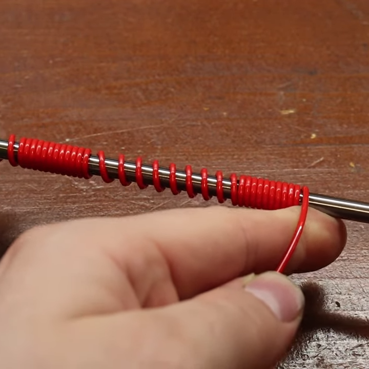
The next time you find yourself in need of some large-ish plastic springs, maybe consider [PattysLab]’s method for making plastic springs out of spare filament. The basic process is simple: tightly wind some 3D printer filament around a steel rod, secure it and wrap it in kapton tape, then heat it up. After cooling, one is left with a reasonably functional spring, apparently with all the advantages of annealed plastic.

The basic process may be simple, but [PattysLab] has a number of tips for getting best results. The first is to use a 3D-printed fixture to help anchor one end of filament to the steel rod, then use the help of an electric drill to wind the filament tightly. After wrapping the plastic with kapton tape (wrap counter to the direction of the spring winding, so that peeling the tape later doesn’t pull the spring apart), he suspends it in a pre-heated oven at 120 C for PLA and 160 C for PETG. How long does it stay in there? [PattysLab] uses the following method: when the spring is wound, he leaves a couple inches of filament sticking out to act as a visual indicator. When this segment of filament sags down, that’s his cue to begin the retrieval process. After cooling, the result is a compression or extension spring, depending on how it was wound before being heated.

[PattysLab] shared a short video on this Reddit post that shows both springs in action, and the process is all covered in the video, embedded below.

This method clearly works for [PattysLab] and doesn’t require any unusual hardware or equipment, but should anyone wish to apply a bit more finesse to the process, this scientific approach to annealing plastics used in 3D printing might come in handy.

source https://hackaday.com/2021/01/06/heat-turns-3d-printer-filament-into-springs/

Custom Controller makes Turbomolecular Pump Suck

[Mark Aren] purchased a pair of Turbomolecular pumps (TMP) sans controllers, and then built an FPGA based BLDC controller for the Turbomolecular pumps. A TMP is similar to a jet turbine, consisting of several stages of alternating moving turbine blades and stationary stator blades, and having turbine rotation speeds ranging from 10,000 rpm to 90,000 rpm. TMP’s cannot exhaust directly to atmosphere, and must be combined with a backing (or roughing) pump to create a lower grade vacuum first. They find use in lots of applications such as electron microscopy, analytical sciences, semiconductors and lamp manufacturing. With the lamp industry rapidly embracing LEDs, many of the traditional lamp making lines are getting decommissioned, and if you are lucky, you can snag a TMP at a low cost – but it still will not be cheap by any means.

The two BOC-Edwards EXT255H Compound Molecular Pumps (PDF), that [Mark] bought did not have their accompanying EXC100E Turbomolecular Pump Controllers (PDF), and given pandemic related restrictions, he decided to build a controller of his own, using components and modules from his parts bin. The pump and controller user manuals offered only sketchy details about the sensored BLDC motor used in the pump. The low phase-to-phase resistance implied low drive voltage, and [Mark] decided to try running it at 24 V to start with. He already had experience using the Mitsubishi PS21245-E IGBT inverter bridge, and even though it was rated for much higher voltages, he knew that it would work just fine at 24 V too.

After figuring out a state machine for motor commutation that utilized PWM based adjustable current control, he implemented it on a 128 element FPGA board. Considering how expensive the TMP was, he wisely decided to first try out his driver on a smaller “expendable” BLDC motor. This whole process was non-trivial, since his available IGBT module was untested and undocumented, and required several tweaks before he could run it at the required 12 kHz PWM signals. His test motor was also undocumented, failing to run correctly when first hooked up. Fixing that issue meant having to disassemble the motor to check its internal wiring. Eventually, his efforts paid off, and he was able to safely run the TMP motor to confirm that his design worked.

With FPGA code, IGBT wiring and power supply issues sorted, the next step was to add a supervisory micro-controller, using an Arduino Nano. Its functions included interfacing with a touch screen LCD as a user interface, communicating with the FPGA module, and controlling several relays to switch power to the motor power supply, the roughing pump, TMP cooling fan, and a solenoid for the vacuum vent. Spindle current is calculated by measuring voltage drop across shunt resistors on the low side of the IGBT. Motor speed is measured using one of the motor hall sensors, and a thermistor provides motor temperature sensing. [Mark]’s PCB fabrication technique seems a bit different too. Using an Excellon drill file, he drills holes in a piece of plastic using a laser cutter to create a bare board, and then solders copper tracks by hand.

His initial tests at atmospheric pressure (although not recommended unless you monitor pump temperature), resulted in 7300 rpm while consuming about 7 Amps before he had to shut it down. In further tests, after adding a roughing pump to the test setup, he was able to spin the TMP to 20,000 rpm while it consumed 0.6 A. Obviously, the pump is rated to operate at a higher voltage, possibly 48 V based on the values mentioned in the TMP controller manual. The project is still “work in progress” as [Mark] hopes to eventually drive the pump up to its specified 60,000 rpm operating speed. What is not clear is what he eventually intends to do with this piece of exotic machinery. All he mentions is that “he has recently taken an interest in high-vacuum systems and is interested in exploring the high-vacuum world of electron guns.”

Maybe [Mark] can compare notes with the Open Source Turbomolecular Pump Controller that we featured some time back. And if you’d like to be a little bit more adventurous and build you own TMP, we got you covered with this DIY Everyman’s Turbomolecular Pump.

source https://hackaday.com/2021/01/06/custom-controller-makes-turbomolecular-pump-suck/

Xbox Controller Mod Gets Serious About Stick Drift

Many a gamer has found that after a few years of racing around the track or sending demons back from whence they came, the analog sticks on their trusty controller can start to drift around. Many times it’s a fairly minor problem, something you might only notice if you were really keeping an eye out for it, but it can definitely be annoying. Those handy with a soldering iron might just swap out the sticks for replacements once it gets to that point, but [Taylor Burley] wondered how difficult it would be to recalibrate the ailing sticks instead.

To be clear, [Taylor] acknowledges this approach is overkill. It would be cheaper and easier to just replace the drifting stick with a new one. Even if you take into account that new sticks might not be as high quality as the originals and could give up the ghost faster, this probably isn’t worth the effort. But that doesn’t mean it’s not an interesting hack.

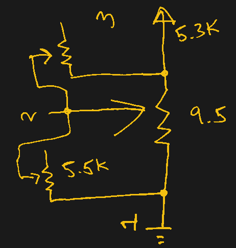
In the video after the break, [Taylor] starts by explaining how stick drift occurs in the first place. Each axis of the stick is physically connected to the wiper of a potentiometer, so for 10K pots, the stick’s center point should correspond to a resistance of 5K. He then goes on to measure the resistance in a bad joystick, and sure enough, the center resistance is off by several hundred Ohms.

To fix this, he comes up with a simple circuit that places additional potentiometers between the wipers. With two joysticks and two adjustment pots per axis, that makes eight little adjustment wheels that need to be fiddled with to get the center points calibrated properly. In this case [Taylor] uses a controller diagnostic tool for the Xbox to quantify the impact his adjustments are making so he can dial it in perfectly, but the idea is the same no matter who’s logo is on the box.

We’d say this is the most overkill attempt at addressing the issue of stick drift on gaming controllers we’ve ever seen, but that title has to go to [Matteo Pisani], who replaced the analog stick on his Switch Joy-Con with a custom circular touchpad.

source https://hackaday.com/2021/01/05/xbox-controller-mod-gets-serious-about-stick-drift/

Xbox Controller Mod Gets Serious About Stick Drift

Many a gamer has found that after a few years of racing around the track or sending demons back from whence they came, the analog sticks on their trusty controller can start to drift around. Many times it’s a fairly minor problem, something you might only notice if you were really keeping an eye out for it, but it can definitely be annoying. Those handy with a soldering iron might just swap out the sticks for replacements once it gets to that point, but [Taylor Burley] wondered how difficult it would be to recalibrate the ailing sticks instead.

To be clear, [Taylor] acknowledges this approach is overkill. It would be cheaper and easier to just replace the drifting stick with a new one. Even if you take into account that new sticks might not be as high quality as the originals and could give up the ghost faster, this probably isn’t worth the effort. But that doesn’t mean it’s not an interesting hack.

In the video after the break, [Taylor] starts by explaining how stick drift occurs in the first place. Each axis of the stick is physically connected to the wiper of a potentiometer, so for 10K pots, the stick’s center point should correspond to a resistance of 5K. He then goes on to measure the resistance in a bad joystick, and sure enough, the center resistance is off by several hundred Ohms.

To fix this, he comes up with a simple circuit that places additional potentiometers between the wipers. With two joysticks and two adjustment pots per axis, that makes eight little adjustment wheels that need to be fiddled with to get the center points calibrated properly. In this case [Taylor] uses a controller diagnostic tool for the Xbox to quantify the impact his adjustments are making so he can dial it in perfectly, but the idea is the same no matter who’s logo is on the box.

We’d say this is the most overkill attempt at addressing the issue of stick drift on gaming controllers we’ve ever seen, but that title has to go to [Matteo Pisani], who replaced the analog stick on his Switch Joy-Con with a custom circular touchpad.

source https://hackaday.com/2021/01/05/xbox-controller-mod-gets-serious-about-stick-drift/

Xbox Controller Mod Gets Serious About Stick Drift

Many a gamer has found that after a few years of racing around the track or sending demons back from whence they came, the analog sticks on their trusty controller can start to drift around. Many times it’s a fairly minor problem, something you might only notice if you were really keeping an eye out for it, but it can definitely be annoying. Those handy with a soldering iron might just swap out the sticks for replacements once it gets to that point, but [Taylor Burley] wondered how difficult it would be to recalibrate the ailing sticks instead.

To be clear, [Taylor] acknowledges this approach is overkill. It would be cheaper and easier to just replace the drifting stick with a new one. Even if you take into account that new sticks might not be as high quality as the originals and could give up the ghost faster, this probably isn’t worth the effort. But that doesn’t mean it’s not an interesting hack.

In the video after the break, [Taylor] starts by explaining how stick drift occurs in the first place. Each axis of the stick is physically connected to the wiper of a potentiometer, so for 10K pots, the stick’s center point should correspond to a resistance of 5K. He then goes on to measure the resistance in a bad joystick, and sure enough, the center resistance is off by several hundred Ohms.

To fix this, he comes up with a simple circuit that places additional potentiometers between the wipers. With two joysticks and two adjustment pots per axis, that makes eight little adjustment wheels that need to be fiddled with to get the center points calibrated properly. In this case [Taylor] uses a controller diagnostic tool for the Xbox to quantify the impact his adjustments are making so he can dial it in perfectly, but the idea is the same no matter who’s logo is on the box.

We’d say this is the most overkill attempt at addressing the issue of stick drift on gaming controllers we’ve ever seen, but that title has to go to [Matteo Pisani], who replaced the analog stick on his Switch Joy-Con with a custom circular touchpad.

source https://hackaday.com/2021/01/05/xbox-controller-mod-gets-serious-about-stick-drift/

AI on the Highway

A couple of announcements caught our attention last week regarding AI-controlled cars. South Korea’s Kakao Mobility and local startup Autonomous A2G launched a limited self-driving taxi service in Sejong City this month, made possible by enabling legislation passed in May. For now, the service is restricted to government employees, and the AI driver will be backed-up by an engineer who is there to monitor the systems and take over in an emergency. The companies plan to expand the fleet and service areas this year, although no details are given.

Another announcement comes from the Ministry of Land, Infrastructure and Transport about the on-going successes of the semi-autonomous truck platooning program. This is a collaboration between the Korean Expressway Corporation, Kookmin University in Seoul, and Hyundai Motors. Previously restricted to a designated test road called the Yeoju Smart Highway, the program is now being tested on public roads at speeds up to 70 kph. This year the program will expand to platoons of 4 trucks running at 90 kph. We’ve always thought that long-haul trucking and freight industries would be an early adaptor AI technologies, and one which AI could offer significant benefits.

source https://hackaday.com/2021/01/05/ai-on-the-highway/

Burned out SKR E3 Mini Gets New Stepper Driver

It didn’t take long to figure out that a dead X axis and an message saying “TMC CONNECTION ERROR” meant that one of the stepper drivers on the SKR E3 Mini 3D printer control board had released the magic smoke. Manufacturer BigTreeTech replaced the board under warranty, and the printer was back up and running in short order. But instead of tossing it in the trash, [Simon] wondered how hard it would be to repair the dead board.

Removing the original stepper driver IC.

The short answer is, not very hard. There was no question as to which of the four TMC2209 drivers was shot, since the X motor was the only one experiencing a problem. The drivers unfortunately aren’t socketed on this board, but after a little kiss with the hot air, the old chip was off.

[Simon] didn’t have any spare TMC2209 chips, but the TMC2208 has the same pinout and is a drop-in replacement. The TMC2208 is rated for a bit less current, but it shouldn’t be a problem under normal circumstances.

Other than the stepper connector getting a little toasty during the installation, the swap went off without a hitch and the board was up and running again. [Simon] ended up putting the now repaired SKR E3 Mini in his Ender 3; a nice 32-bit upgrade compared to the ATmega1284 that was originally running the show. Though in the past, he’s managed to squeeze a bit more performance out of the older 8-bit board as well.

source https://hackaday.com/2021/01/05/burned-out-skr-e3-mini-gets-new-stepper-driver/

Burned out SKR E3 Mini Gets New Stepper Driver

It didn’t take long to figure out that a dead X axis and an message saying “TMC CONNECTION ERROR” meant that one of the stepper drivers on the SKR E3 Mini 3D printer control board had released the magic smoke. Manufacturer BigTreeTech replaced the board under warranty, and the printer was back up and running in short order. But instead of tossing it in the trash, [Simon] wondered how hard it would be to repair the dead board.

Removing the original stepper driver IC.

The short answer is, not very hard. There was no question as to which of the four TMC2209 drivers was shot, since the X motor was the only one experiencing a problem. The drivers unfortunately aren’t socketed on this board, but after a little kiss with the hot air, the old chip was off.

[Simon] didn’t have any spare TMC2209 chips, but the TMC2208 has the same pinout and is a drop-in replacement. The TMC2208 is rated for a bit less current, but it shouldn’t be a problem under normal circumstances.

Other than the stepper connector getting a little toasty during the installation, the swap went off without a hitch and the board was up and running again. [Simon] ended up putting the now repaired SKR E3 Mini in his Ender 3; a nice 32-bit upgrade compared to the ATmega1284 that was originally running the show. Though in the past, he’s managed to squeeze a bit more performance out of the older 8-bit board as well.

source https://hackaday.com/2021/01/05/burned-out-skr-e3-mini-gets-new-stepper-driver/

Burned out SKR E3 Mini Gets New Stepper Driver

It didn’t take long to figure out that a dead X axis and an message saying “TMC CONNECTION ERROR” meant that one of the stepper drivers on the SKR E3 Mini 3D printer control board had released the magic smoke. Manufacturer BigTreeTech replaced the board under warranty, and the printer was back up and running in short order. But instead of tossing it in the trash, [Simon] wondered how hard it would be to repair the dead board.

Removing the original stepper driver IC.

The short answer is, not very hard. There was no question as to which of the four TMC2209 drivers was shot, since the X motor was the only one experiencing a problem. The drivers unfortunately aren’t socketed on this board, but after a little kiss with the hot air, the old chip was off.

[Simon] didn’t have any spare TMC2209 chips, but the TMC2208 has the same pinout and is a drop-in replacement. The TMC2208 is rated for a bit less current, but it shouldn’t be a problem under normal circumstances.

Other than the stepper connector getting a little toasty during the installation, the swap went off without a hitch and the board was up and running again. [Simon] ended up putting the now repaired SKR E3 Mini in his Ender 3; a nice 32-bit upgrade compared to the ATmega1284 that was originally running the show. Though in the past, he’s managed to squeeze a bit more performance out of the older 8-bit board as well.

source https://hackaday.com/2021/01/05/burned-out-skr-e3-mini-gets-new-stepper-driver/

The Last Component Storage System You’d Ever Need

Think you’ve seen the best component storage system? This system could only be better if you could walk up and talk to it. [APTechnologies] was tired of using a hodgepodge of drawers and boxen for storing their components. What they needed was an all-purpose solution for storing all kinds of small-to-medium-sized goodies, be they through hole or SMT.

This one happens to have a software interface as well that is searchable with short, crisp expressions that find parts by ID or with parameters. It’s a Python 3 script running on a Raspberry Pi 4B that’s hiding behind the HDMI display. [APTechnologies] printed a special arm for that, and you can find all the files on GitHub. Not only does the LED above the corresponding drawer light up, it lights up in a color that represents the inventory levels. We assume green/yellow/red, but [APTechnologies] doesn’t specify.

Don’t know what to do with some of your components? If they’re really old, they may be no good anymore. It just depends.

source https://hackaday.com/2021/01/05/the-last-component-storage-system-youd-ever-need/

Remoticon Video: Meta_Processing Is a Mashup of Text and Block Programming

Very few people want to invent the universe before they blink their first LED. Sure, with enough interest a lot of folks will drill-down to the atomic level of technology and build their way back up. But there’s something magical about that first time you got your blinky to blink, and knowing how to write makefiles plays no part in that experienc). Now apply that to projects using smartphone as wireless interfaces… how simple can we make it for people?

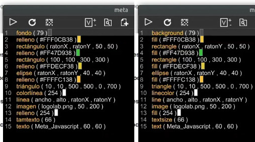
Meta_Processing can translate the instructions into any of 14 languages

Jose David Cuartas is working to answer that very question and gives us a guided tour of his progress in this Meta_Processing workshop held during the Hackaday Remoticon. Meta-Processing is an IDE based on — as you’ve probably guessed — Processing, the programming language that unlocked higher-level functionality to anyone who wanted to perform visually-interesting things without becoming software zen masters. The “Meta_” part here is that it can now be done with very limited typing and interchangeably between different spoken languages.

The approach is to take the best of text programming and block programming languages and mash them together. In that way, you don’t type new lines, you add them with a click of the mouse and select the instruction you want to use on that line from a list. It means you don’t need to have the instructions memorized, and avoids typos in your code. The docs for that instruction will be shown on the bottom bar of the IDE to help you with parameters. And the kicker is that since you’re selecting the instructions, choosing any of the IDE’s 14 available spoken languages will update your “code” with translations into the new language.

In the workshop, video of which is included below, Jose demonstrates a number if interesting examples including audio, video, and user input, using a surprisingly small amount of code. The IDE even spawns a server on the network so that the apps you’ve written can be loaded by a smartphone. It has support for communicating with Arduino-compatible devices with digital read/write, analog read, and servo control. There’s even a fork of the project called Meta_Javascript that rolls in the ability to work with REST-like APIs.

People learn in many different ways. Having options like this to help people get to blinky very quickly is a great way to break down barriers to understanding and using computers.

source https://hackaday.com/2021/01/05/remoticon-video-meta_processing-is-a-mashup-of-text-and-block-programming/

Inputs of Interest: DecaTxt Ultra-Portable Chording Keyboard

Now here’s a stocking stuffer of a keyboard. The DecaTxt is the size of a deck of cards, and at first glance it looks like some kind of pocket Keno machine or other gambling or gaming apparatus. But that’s just because it’s so colorful. When you only have ten keys emulating a full keyboard, there’s bound to be some serious labeling going on, as there should be.

DecaTxt demonstration from IN10DID

The DecaTxt is a Bluetooth 4.0 chording keyboard that’s meant to be used with your phone or whatever you want to pair it with. It was originally called the In10did, which stands for Input Nomenclature Ten Digit Interface Device. Catchy, no? At some point in the last ten years, this little guy went wireless and got a cooler name — the DecaTxt.

By itself, a chording keyboard isn’t that special, but this one is fairly interesting in its design. You can operate it with either one hand or two, but you’re supposed to want to use two — it was after all the In10did, not the In5did. All the chords are a maximum of three keys, so it’s not as though you need to use both hands. Some letters are accessed with a single key press, namely A through J. The rest of the alphabet uses one of the two thumb keys at the top in conjunction with the eight keys on the front. Everything else is a color-coded pair or trio of key presses away.

The idea behind this keyboard is to use your ten digits to maximum advantage, planting your thumbs on top and curling your fingers around the thing in a two-fisted, white-knuckle death grip that seems anything but ergonomic and more appropriate for, say, cracking open a coconut or separating a block of ramen into two servings. Actual users report a much better experience using it one-handed while bracing it against themselves as demonstrated in the video below. That definitely looks like the more comfortable way to go.

Ergonomic issues aside, once you learn the layout, the DecaTxt could theoretically be put into any housing and it wouldn’t matter. That is, in fact, sort of the company’s ultimate goal — to supplant QWERTY with the DecaTxt system and get it built into everything under the Sun — gloves, steering wheels, ATMs, you name it.

I think the basic idea of this keyboard is sound, and the layout could definitely be reworked into a more ergonomic housing (and probably for a lot cheaper than the $125 Bezos Barn price tag). According to the inventor, the price is so high because every DecaTxt is hand-assembled in the United States. As far as I can tell it only comes in one size, which is a bummer for people with particularly large or small hands.

I recently looked at another chording keyboard — the Infogrip BAT, which is a full keyboard with only seven keys. Both are chording keebs that do single glyphs instead of entire words, like stenography machines. The BAT is is designed for desktop use and roughly four times the size of the DecaTxt, so it’s not quite as portable, but its size and shape goes a long way toward ergonomic comfort. The DecaTxt is definitely more mobile friendly — easy to pop in a backpack — but the tradeoff is the loss of that ergonomic design.

Have you tried a chording keyboard like this one? Would you be willing to try one? How would you make it better? Here’s one you can build yourself.

source https://hackaday.com/2021/01/05/inputs-of-interest-decatxt-ultra-portable-chording-keyboard/

Raspberry Pi 4 Brings Cloud Gaming to Nintendo Switch

Companies like Google and Microsoft have been investing heavily in the concept of cloud gaming, where a player uses their computer or a mobile device to stream the video feed of a game that’s running on powerful machine tucked away in a data center somewhere. With this technology you can play the latest and greatest titles, even if the device you’re using doesn’t have the processing power to run it locally.

Considering the Switch is already a portable system, it’s not too surprising Nintendo doesn’t seem interested in the technology. But that didn’t stop [Stan Dmitriev] from doing a bit of experimentation on his own. With little more than a Raspberry Pi 4 and Trinket M0, he’s demonstrated that users can remotely interact with the Switch well enough to play games in real time.

The setup is fairly straightforward. A cheap HDMI capture device is used to grab the video from the Nintendo Switch dock, which is then streamed out to web with the help of the Pi’s hardware video encoder. Input from the user is sent over the Pi’s UART to the Trinket, which itself is running a firmware specifically developed for mimicking Nintendo Switch controllers. With so many elements involved, naturally some latency comes into play. The roughly 100 millisecond delay [Stan] is reporting isn’t exactly ideal for fast-paced gaming, but is certainly adequate for more relaxed titles.

On the software side of things, the project is using a SDK developed by [Stan]’s employer SurrogateTV. Right now you need to apply if you want to get your game or other interactive gadget up on the service, though he says it will be opened up to the public next year. But even without all the details, we’ve got a clear idea of how both the video capture and user input sides of the equation are being handled. For personal use, all you’d really need to do is put together a simple web interface to tie it all together.

This isn’t the first time we’ve seen a microcontroller used to interface with the Switch. Other consoles are a bit more selective about what kind of hardware they will talk to, but the Microsoft Adaptive Controller could potentially allow you to do something similar on the Xbox.

source https://hackaday.com/2021/01/05/raspberry-pi-4-brings-cloud-gaming-to-nintendo-switch/

[Ben Eater]’s Breadboarding Tips

A solderless breadboard is a place where ideas go to become real for the first time. Usually, this is a somewhat messy affair, with random jumpers flying all about the place, connecting components that can be quickly swapped to zero in on the right values, or to quickly change the circuit topology. Breadboards aren’t the place to make circuit artwork.

That is, however, not always the case, and we’ve seen more than a few examples from [Ben Eater] on breadboarding that approaches the circuit sculpture level of craftsmanship. And like any good craftsman, [Ben] has shared some of his breadboarding tips and tricks in a new video. Starting with a simple 555 blinkenlight project that’s wired up in the traditional anything-goes fashion, [Ben] walks us through his process for making a more presentation-worthy version.

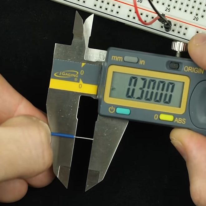
His tools are high-quality but simple, with the wire strippers being the most crucial to good results. Surprisingly, [Ben] relies most heavily on the simple “scissors-style” strippers for their versatility, rather than the complicated semi-automatic tools. We found that to be the biggest take-home from the video, as well as the results of practice. [Ben] has done tons of this type of breadboarding before, which means when he “eyeballs” stripping 0.3 inches of insulation, he can do it down to a ten-thousandth precision.

Granted, there’s not much new here, but watching this video is a little like watching [Bob Ross] paint — relaxing and strangely compelling at the same time. You can get more of the same with pretty much any of his videos that we’ve covered, like this 6502 breadboard computer build. We’ve also seen [Eater]-inspired builds that are pretty impressive, like this full-8-bit breadboard computer.

source https://hackaday.com/2021/01/05/ben-eaters-breadboarding-tips/

[Ben Eater]’s Breadboarding Tips

A solderless breadboard is a place where ideas go to become real for the first time. Usually, this is a somewhat messy affair, with random jumpers flying all about the place, connecting components that can be quickly swapped to zero in on the right values, or to quickly change the circuit topology. Breadboards aren’t the place to make circuit artwork.

That is, however, not always the case, and we’ve seen more than a few examples from [Ben Eater] on breadboarding that approaches the circuit sculpture level of craftsmanship. And like any good craftsman, [Ben] has shared some of his breadboarding tips and tricks in a new video. Starting with a simple 555 blinkenlight project that’s wired up in the traditional anything-goes fashion, [Ben] walks us through his process for making a more presentation-worthy version.

His tools are high-quality but simple, with the wire strippers being the most crucial to good results. Surprisingly, [Ben] relies most heavily on the simple “scissors-style” strippers for their versatility, rather than the complicated semi-automatic tools. We found that to be the biggest take-home from the video, as well as the results of practice. [Ben] has done tons of this type of breadboarding before, which means when he “eyeballs” stripping 0.3 inches of insulation, he can do it down to a ten-thousandth precision.

Granted, there’s not much new here, but watching this video is a little like watching [Bob Ross] paint — relaxing and strangely compelling at the same time. You can get more of the same with pretty much any of his videos that we’ve covered, like this 6502 breadboard computer build. We’ve also seen [Eater]-inspired builds that are pretty impressive, like this full-8-bit breadboard computer.

source https://hackaday.com/2021/01/05/ben-eaters-breadboarding-tips/

[Ben Eater]’s Breadboarding Tips

A solderless breadboard is a place where ideas go to become real for the first time. Usually, this is a somewhat messy affair, with random jumpers flying all about the place, connecting components that can be quickly swapped to zero in on the right values, or to quickly change the circuit topology. Breadboards aren’t the place to make circuit artwork.

That is, however, not always the case, and we’ve seen more than a few examples from [Ben Eater] on breadboarding that approaches the circuit sculpture level of craftsmanship. And like any good craftsman, [Ben] has shared some of his breadboarding tips and tricks in a new video. Starting with a simple 555 blinkenlight project that’s wired up in the traditional anything-goes fashion, [Ben] walks us through his process for making a more presentation-worthy version.

His tools are high-quality but simple, with the wire strippers being the most crucial to good results. Surprisingly, [Ben] relies most heavily on the simple “scissors-style” strippers for their versatility, rather than the complicated semi-automatic tools. We found that to be the biggest take-home from the video, as well as the results of practice. [Ben] has done tons of this type of breadboarding before, which means when he “eyeballs” stripping 0.3 inches of insulation, he can do it down to a ten-thousandth precision.

Granted, there’s not much new here, but watching this video is a little like watching [Bob Ross] paint — relaxing and strangely compelling at the same time. You can get more of the same with pretty much any of his videos that we’ve covered, like this 6502 breadboard computer build. We’ve also seen [Eater]-inspired builds that are pretty impressive, like this full-8-bit breadboard computer.

source https://hackaday.com/2021/01/05/ben-eaters-breadboarding-tips/