Have you dipped your toe into the SDR ocean? While hacker software-defined radio has been a hot topic for years now, it can be a little daunting to try it out for the first time. Here’s your change to get your legs under you with the SDR overview workshop presented by Josh Conway during the 2020 Hackaday Remoticon.
Josh’s presentation starts with a straightforward definition of SDR before moving to an overview of the hardware and software that’s out there. Hardware designs for radios can be quite simple to build, but they’ll be limited to a single protocol — for instance, an FM radio can’t listen in on 433 Mhz wireless doorbell. SDR breaks out of that by moving to a piece of radio hardware that can be reconfigured to work with protocols merely by making changes to the software that controls it. This makes the radio hardware more expensive, but also means you can listen (and sometimes transmit) to a wide range of devices like that wireless doorbell or automotive tire pressure sensors, but also radio-based infrastructure like airplane transponders and weather satellites.
This is the quickstart you want since it explains a lot of topis at just the right depth. The hardware overview covers RTL-SDR, ADALM-PLUTO, HackRF, KerberosSDR, and BladeRF (which we just featured over the weekend used on the WiFi procotol). For software, Josh recaps GQRX, SDR#, SDRAngel, ShinySDR, Universal Radio Hacker, Inspectrum, SigDigger, RPITX, GnuRadio Companion, and REDHAWK. He also takes us through a wide swath of the antenna types that are out there before turning to questions from the workshop attendees.
If SDR is still absent in your toolbox, now’s a great time to give it another look. Once you’ve made it through the ‘hello world’ stage, there’s plenty to explore like those awesome RF Emissions testing tricks we as in another Remoticon talk.
When the Space Shuttle Atlantis rolled to a stop on its final mission in 2011, it was truly the end of an era. Few could deny that the program had become too complex and expensive to keep running, but even still, humanity’s ability to do useful work in low Earth orbit took a serious hit with the retirement of the Shuttle fleet. Worse, there was no indication of when or if another spacecraft would be developed that could truly rival the capabilities of the winged orbiters first conceived in the late 1960s.
While its primary function was to carry large payloads such as satellites into orbit, the Shuttle’s ability to retrieve objects from space and bring them back was arguably just as important. Throughout its storied career, sensitive experiments conducted at the International Space Station or aboard the Orbiter itself were returned gently to Earth thanks to the craft’s unique design. Unlike traditional spacecraft that ended their flight with a rough splashdown in the open ocean, the Shuttle eased itself down to the tarmac like an airplane. Once landed, experiments could be quickly unloaded and transferred to the nearby Space Station Processing Facility where science teams would be waiting to perform further processing or analysis.
Atlantis is towed from the runway for payload processing.
For 30 years, the Space Shuttle and its assorted facilities at Kennedy Space Center provided a reliable way to deliver fragile or time-sensitive scientific experiments into the hands of researchers just a few hours after leaving orbit. It was a valuable service that simply didn’t exist before the Shuttle, and one that scientists have been deprived of ever since its retirement.
Until now. With the successful splashdown of the first Cargo Dragon 2 off the coast of Florida, NASA is one step closer to regaining a critical capability it hasn’t had for a decade. While it’s still not quite as convenient as simply rolling the Shuttle into the Orbiter Processing Facility after a mission, the fact that SpaceX can guide their capsule down into the waters near the Space Coast greatly reduces the time required to return experiments to the researchers who designed them.
On Dragon’s Wings
While it took nearly ten years to resume crewed launches from American soil after the retirement of the Space Shuttle, there wasn’t nearly as much of a downtime for cargo flights. SpaceX put their first Dragon capsule into orbit in 2010, and just over a year after the final flight of Atlantis, they were ready to begin regular resupply missions to the International Space Station. Not only could the privately developed craft carry a combined 6,000 kilograms (13,000 pounds) of pressurized and unpressurized cargo to the orbiting outpost, it could also bring approximately 3,000 kg (6,600 lbs) back down to Earth.
By 2012, SpaceX had already sent a Dragon to the ISS.
In comparison, the Shuttle could safely land with around 14,400 kg (31,700 lbs) packed in its cavernous cargo bay. But realistically, that capacity was intended for hauling satellites and was completely overkill for simply returning racks of scientific experiments. Price was also a consideration: a Dragon mission cost NASA just a fraction of what a Shuttle flight did. Combined with the much higher launch cadence of the Dragon, it’s clear which vehicle was better suited to performing regular “milk runs” up to the ISS and back.
But there was a downside. Despite SpaceX’s stated intention to one day perform pin-point propulsive landings with the Dragon, the small spacecraft ended up splashing down in the ocean under parachutes just like the Apollo and Gemini capsules before it. This meant returning to Earth on a Dragon was a much rougher ride than what the Shuttle offered. While not a problem for many payloads, it could be a ruinous experience for sensitive experiments such as those designed to study crystal growth in microgravity.
Further complicating matters was the fact that the capsule came down in the Pacific Ocean, several hundred kilometers off the coast. This made recovery operations easier for the California-based SpaceX, but as NASA lacked suitable payload processing facilities on the West Coast, returning cargo would need to be transported to Johnson Space Center in Houston or all the way back to Kennedy Space Center. The prospect of experiments potentially having to endure a cross-country flight before they could be released to scientists made certain research difficult or impossible to accomplish.
The Human Element
While hardly ideal, landing cargo and experiments on the West Coast and flying them back to Florida was still better than having to transport them back from Kazakhstan if they flew on a Soyuz. But it wouldn’t quite do when it came time for SpaceX to start carrying astronauts as part of the Commercial Crew Program. NASA wanted the primary splashdown point for the new Crew Dragon to be as close to Kennedy Space Center as possible to leverage the existing Shuttle era resources and facilities, with a splashdown in the Gulf of Mexico reserved for contingencies.
GO Navigator with Crew Dragon onboard.
This required a considerable expansion of SpaceX’s recovery capabilities. Two ships, GO Searcher and GO Navigator, were procured by the company and outfitted with medical facilities, a helipad, and a lifting apparatus on the stern for hoisting the floating Crew Dragon capsule onto the deck. For redundancy the two craft are virtually identical and can be deployed simultaneously.
With the operational assets and trained personnel moved to East Coast for Crew Dragon, recovering the cargo variant of the spacecraft in California no longer made fiscal sense. Besides, given how similar the two vehicles are, experience gained while pulling the Cargo Dragon from the ocean would serve to improve crewed recovery operations. As NASA’s requirements state that astronauts must egress the capsule within 60 minutes of splashdown, the teams need all the practice they can get.
Beyond the faster delivery time, Cargo Dragon has a number of other advantages over its predecessor. The upgraded capsule has increased payload capacity, twice the number of climate controlled lockers for storing sensitive materials, and a fully autonomous docking system that reduces the workload for astronauts aboard the orbiting outpost. It can also be more easily refurbished for reuse, which not only lowers costs but allows for a higher launch cadence than would be possible otherwise.
Chasing the Dream
With a helicopter waiting to take time-sensitive payloads from the recovery ship to the Space Station Processing Facility, SpaceX can now deliver experiments to scientists between four and nine hours after splashdown. This is a vast improvement over what was possible previously, and arguably the best that can be realistically expected for an off-shore operation. But it’s still not a fast as the Space Shuttle.
Ultimately, having to pull the spacecraft from the ocean and transporting the human crew members or scientific payloads back to land via helicopter will always take longer than simply landing the vehicle at a designated facility. Since SpaceX is no longer pursuing targeted propulsive landings with their Dragon spacecraft, that means another company will have to step up to meet the challenge of truly rapid payload return.
Dream Chaser prototype during testing.
As it so happens, that’s precisely what the Sierra Nevada Corporation hopes to do with their Dream Chaser spaceplane. Currently slated to fly in 2022 as part of NASA’s Commercial Resupply Services-2 program, the vehicle can return as much as 1,750 kg (3,860 lbs) of cargo to a gentle horizontal landing. Being a quarter the size of the Space Shuttle Orbiter, the Dream Chaser has the advantage of being able to use any runway long enough to accommodate a large passenger plane.
This ability to land essentially anywhere on the planet has clear benefits for international scientific collaboration. But more importantly, when the company completes work on their human-rated variant of the spacecraft, it could be a potentially life-saving capability in the event that a medical emergency necessitates a crew member be transported back to Earth as quickly as possible.
Space Force Leads the Way
The fact that multiple commercially operated spacecraft are now in competition to bring cargo and crew members to the International Space Station and beyond is an incredible achievement. It’s something that many people in the industry believed would never happen, and things are just getting started. The next decade will see several more vehicles and boosters come online, all fighting to be the fastest, most reliable, and of course, cheapest. The democratization of space has officially begun.
The X-37B on the Shuttle runway at Kennedy Space Center.
But as has often been the case historically, it seems that the military is considerably ahead of the curve. The Boeing X-37B spaceplane, now being operated by the newly formed Space Force, is an ideal platform for orbital research and development that in many ways exceeds the capabilities of its commercial peers.
Naturally there’s still a lot we don’t know about the secretive craft, but its ability to conduct free-flying experiments and return scientific payloads from space to a soft runway landing has been publicly demonstrated several times. Being fully autonomous, the X-37B is also able to remain in orbit for far longer than any crewed vehicle. This provides a unique opportunity to conduct long-duration experiments in complete isolation; something that simply isn’t possible on the bustling International Space Station.
As you might expect for a shadowy military operation, most of the research being conducted aboard the X-37B is classified. Some believe the vehicle is designed to evaluate new reconnaissance equipment and techniques, while others think its a test platform for anti-satellite weaponry. But there are signs that the Space Force is willing to share its miniature spaceplane with non-military researchers, with the last launch in May carrying a record number of NASA experiments.
In the end, none of these vehicles can carry more scientific payload than the Space Shuttle, and to date, only the government-operated craft is able to approach the sort of rapid turnaround necessary for the truly time-sensitive experiments. But for the first time in history there’s an array of competitive choices available to researchers who want to get their payload into space and back down in one piece; and that’s definitely a step in the right direction.
So far in the $50 Ham series, I’ve concentrated mainly on the VHF and UHF bands. The reason for this has to do mainly with FCC rules, which largely restrict Technician-level licensees to those bands. But there’s a financial component to it, too; high-frequency (HF) band privileges come both at the price of learning enough about radio to pass the General license test, as well as the need for gear that can be orders of magnitude more expensive than a $30 handy-talkie radio.
But while HF gear can be expensive, not everything needed to get on the air has to be so. And since it’s often the antenna that makes or breaks an amateur radio operator’s ability to make contacts, we’ll look at a simple but versatile antenna design that can be adapted to support everything from a big, powerful base station to portable QRP (low-power) activations in the field: the end-fed half-wave antenna.
Making a Match
There are plenty of hams out there for whom antenna building is the be-all and end-all of the hobby. I get that; there’s a non-zero amount of wizardry that goes into designing an antenna that will do what you want it to do electrically, and plenty of engineering involved in making sure it stands up to the elements. I think the latter aspect of antenna building is more attractive to me personally. Getting an antenna to survive wind, snow, sun, and rain is an interesting challenge, so I tend to spend more time thinking about the mechanical aspects of design that someone has already worked the RF bugs out of.
So I set out looking for an antenna that would work for my situation. Perhaps the easiest antenna to build is the classic half-wave dipole. These have two elements, each one-quarter of the design wavelength, radiating out from a central feed point, which is where the coaxial cable feedline attaches. There are elaborations and complications, of course, but the basic issue for me is the central feed point. My shack is located at the very back corner of my property, so it’s difficult to rig an antenna like that without a long feedline, which can introduce unacceptable signal losses. Plus, a dipole for the 80-meter band would be 40 meters end-to-end, and that would be hard to fit across my long, narrow suburban lot.
For my purposes, the end-fed half-wave (EFHW) antenna is a good choice. It’s exactly what it sounds like: a chunk of wire one-half of a wavelength long (in my case, 40 meters long so I can work the 80 meter band) that is fed from its end. But it’s not as simple as cutting a 40 meter long piece of wire and sticking it on your radio. The problem is that the impedance of an antenna varies as the feedpoint moves away from the center. The impedance increases all the way up to about 2,500 ohms when the feedpoint reaches the end of the wire, which would be a very bad match indeed for a transceiver expecting a 50 ohm load.
To fix this, EFHW antennas need a transformer to match impedances. When used to match impedance between a balanced antenna, like a dipole, and an unbalanced feedline, like coaxial cable, these are referred to as “baluns”. In this case, though, both the antenna and the coax feedline are unbalanced, so the transformer I built is technically an “unun”. Whatever you call it, it’s a pretty easy build.
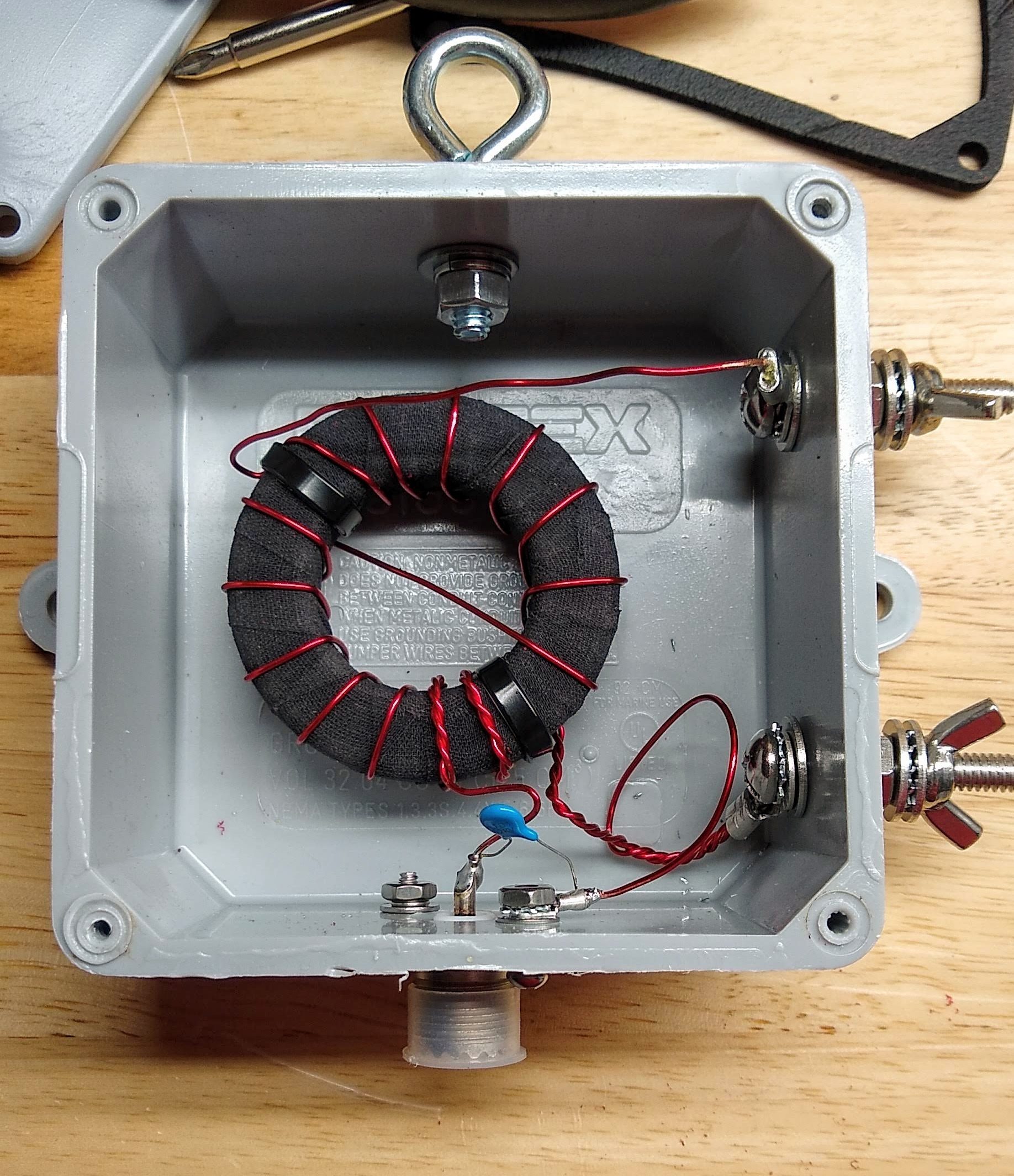
My 49:1 matching transformer, mounted and ready to go outside. I considered potting the hole thing in epoxy, but decided against it.
I followed the excellent instructions provided by Steve Nichols (G0KYA) to wind my 49:1 autotransformer. It’s basically just big ferrite toroid core — I got mine from eBay, but there are plenty of options on Amazon — with a few windings of magnet wire. My core is an FT-240-61, which means its outside diameter is 2.4 inches and it’s made of type 61 material. I used 18 AWG magnet wire for the windings. While I was winding it, I noticed that the lacquer coating on the magnet wire was getting nicked by the edges of the ferrite core. I rewound it after covering the toroid with cloth friction tape to cushion the edges a bit — shorts would be no bueno in something designed to handle 100 Watts of transmitter output.
Like I said, a lot of the fussing I did with this transformer had to do with making it work mechanically. I mounted it into a sturdy plastic electrical enclosure and provided stainless steel fittings for connecting the antenna wire and the ground connection. I also installed an eye bolt to tether the antenna wire. A good-quality SO-239 socket for the feedline connection and a 100 pF high-voltage capacitor for better matching on the higher frequency bands completed the transformer. With luck, this antenna should cover 80 m to 10 m bands.
Pushing Rope
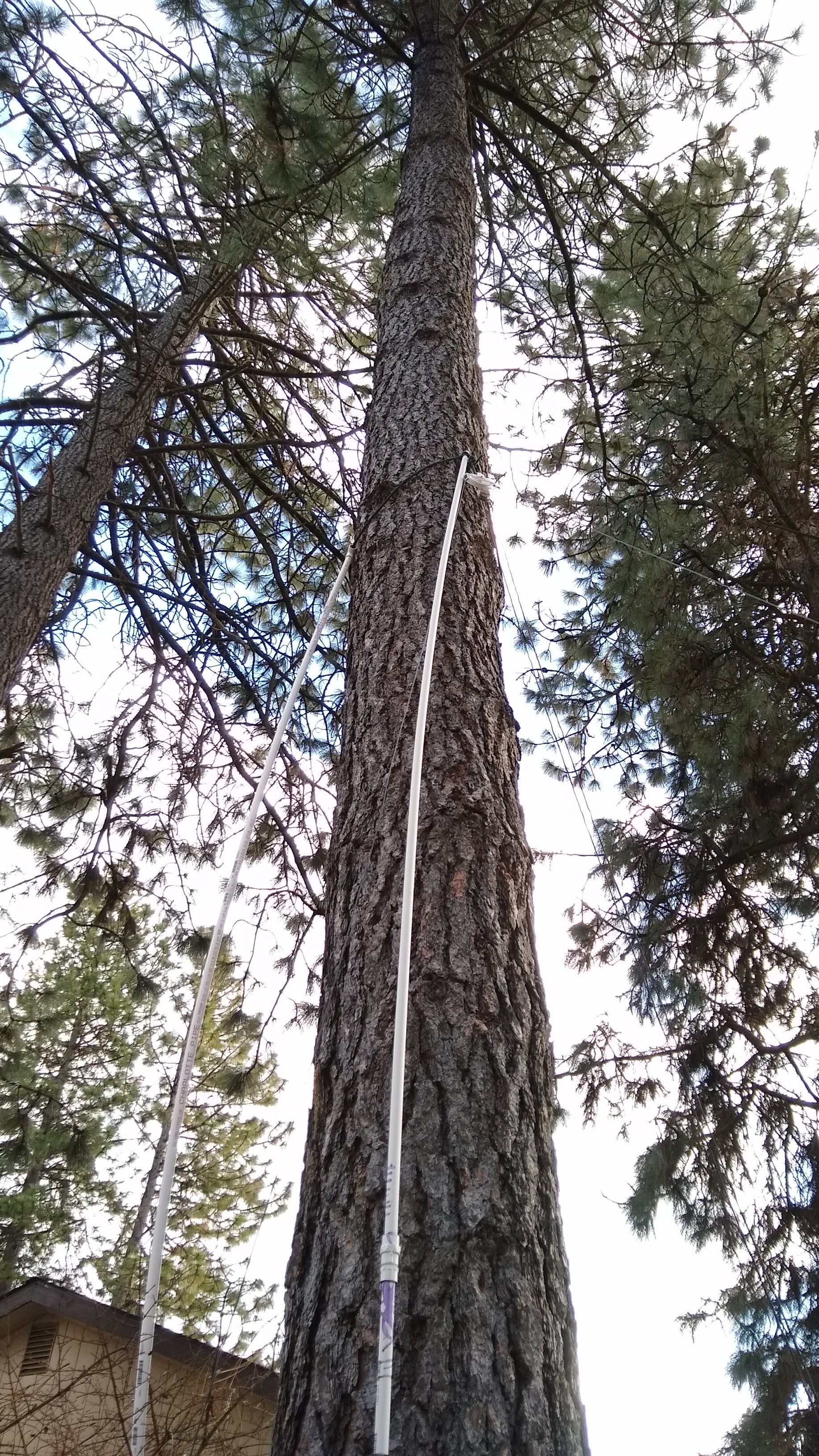
My method for placing a pulley up a tree from the ground. It would have work better on a tree with smoother bark.
As luck would have it, my lot is just about 150 feet deep, and I’m both blessed and cursed by a lot of very tall, very sturdy Ponderosa pines. The length of my lot and the location of the trees allows for a full 40-meter wire in a sort of “inverted-L” configuration. My plan was to slope the wire from the transformer up as far as possible in the first tree, then run it horizontally to an anchor point in a second tree.
This sounds far, far easier than it actually is. While many hams have had good luck suspending antennas from lines lofted over branches, my pine trees have all been pruned of their lower branches, with the first living branches more than 40′ (12 meters) above the ground. I opted for a “work smarter” approach and came up with an idea to basically push a loop of rope up the tree using PVC pipe as a push stick. Although the roughness of the Ponderosa bark constantly snagged the nylon rope and the PVC pipe flopped around as I added sections , it actually worked well enough to get the anchor point about 25′ (7.5 m) above the ground — not much higher than I could have gotten with my 24′ ladder, but with a whole lot less risk of falling to my death.
The anchor point was set in the other tree using a similar method, which drew a lot of attention from the neighbors. One should always seize such opportunities to do a little “ham goodwill” outreach, and I assured the neighbors that I wouldn’t be sterilizing their kids or interfering with their TV reception. In an example of karma, though, the tree I was working in decided to shed a dead branch the next day, which came down and damaged my neighbor’s Durango. It clearly came from much higher in the tree than I was working, but it still caused a little bit of the old stink eye.
Sway relief on the anchor end. Note the safety line that runs through the bore of the spring, just in case it breaks.
One of the most important parts of using trees as anchors for long-wire antennas is dealing with sway. Trees move around quite a bit, and if you anchor a wire tightly between two trees without allowing for them to move with the wind, sadness will ensue. And yet, you want your wire to stay more or less taut, since its shape affects its performance. There are a couple of ways to deal with this, and I chose to use clothesline pulleys at both my anchor points. At the midpoint, the wire runs through the pulley; at the end anchor, the wire is tied off to a length of strong nylon cord through a dogbone insulator. That cord runs through the pulley and down the trunk of the tree to an anchor point through a strong spring. When the trees sway, the antenna can extend or retract by several inches without sagging or snapping.
On the Air at Last
I have to admit that this installation isn’t actually complete yet. Antennas really should be properly grounded, and I’m keen to pound a ground rod in near the transformer. However, both the mains feeder for my house and the primary feeder for the entire neighborhood are buried directly under our back fence, making this a high-risk endeavor. As good as underground location services are, I’m not keen to test their precision with my precious self. So I’m going to wait for a decent ground.
Still, I couldn’t help but want to try this antenna out, so to keep RF out of the shack, I would a 10-turn air-core choke on the feedline and hooked it up. I haven’t made any QSOs yet, but using WSPR, the Weak Signal Propagation Reporter system, I was able to reach four continents over a 24-hour period on the 80-, 40-, 30-, and 20-meter bands.
The world on one antenna: 24 hours of WSPR reports on 80, 40, 30, and 20 meters.
And speaking of WSPR, that and other digital modes are what we’ll be talking about in the next installment of the $50 Ham. Spoiler alert: despite my previous gripes, I think I’m falling in love with ham radio again.
So far in the $50 Ham series, I’ve concentrated mainly on the VHF and UHF bands. The reason for this has to do mainly with FCC rules, which largely restrict Technician-level licensees to those bands. But there’s a financial component to it, too; high-frequency (HF) band privileges come both at the price of learning enough about radio to pass the General license test, as well as the need for gear that can be orders of magnitude more expensive than a $30 handy-talkie radio.
But while HF gear can be expensive, not everything needed to get on the air has to be so. And since it’s often the antenna that makes or breaks an amateur radio operator’s ability to make contacts, we’ll look at a simple but versatile antenna design that can be adapted to support everything from a big, powerful base station to portable QRP (low-power) activations in the field: the end-fed half-wave antenna.
Making a Match
There are plenty of hams out there for whom antenna building is the be-all and end-all of the hobby. I get that; there’s a non-zero amount of wizardry that goes into designing an antenna that will do what you want it to do electrically, and plenty of engineering involved in making sure it stands up to the elements. I think the latter aspect of antenna building is more attractive to me personally. Getting an antenna to survive wind, snow, sun, and rain is an interesting challenge, so I tend to spend more time thinking about the mechanical aspects of design that someone has already worked the RF bugs out of.
So I set out looking for an antenna that would work for my situation. Perhaps the easiest antenna to build is the classic half-wave dipole. These have two elements, each one-quarter of the design wavelength, radiating out from a central feed point, which is where the coaxial cable feedline attaches. There are elaborations and complications, of course, but the basic issue for me is the central feed point. My shack is located at the very back corner of my property, so it’s difficult to rig an antenna like that without a long feedline, which can introduce unacceptable signal losses. Plus, a dipole for the 80-meter band would be 40 meters end-to-end, and that would be hard to fit across my long, narrow suburban lot.
For my purposes, the end-fed half-wave (EFHW) antenna is a good choice. It’s exactly what it sounds like: a chunk of wire one-half of a wavelength long (in my case, 40 meters long so I can work the 80 meter band) that is fed from its end. But it’s not as simple as cutting a 40 meter long piece of wire and sticking it on your radio. The problem is that the impedance of an antenna varies as the feedpoint moves away from the center. The impedance increases all the way up to about 2,500 ohms when the feedpoint reaches the end of the wire, which would be a very bad match indeed for a transceiver expecting a 50 ohm load.
To fix this, EFHW antennas need a transformer to match impedances. When used to match impedance between a balanced antenna, like a dipole, and an unbalanced feedline, like coaxial cable, these are referred to as “baluns”. In this case, though, both the antenna and the coax feedline are unbalanced, so the transformer I built is technically an “unun”. Whatever you call it, it’s a pretty easy build.
My 49:1 matching transformer, mounted and ready to go outside. I considered potting the hole thing in epoxy, but decided against it.
I followed the excellent instructions provided by Steve Nichols (G0KYA) to wind my 49:1 autotransformer. It’s basically just big ferrite toroid core — I got mine from eBay, but there are plenty of options on Amazon — with a few windings of magnet wire. My core is an FT-240-61, which means its outside diameter is 2.4 inches and it’s made of type 61 material. I used 18 AWG magnet wire for the windings. While I was winding it, I noticed that the lacquer coating on the magnet wire was getting nicked by the edges of the ferrite core. I rewound it after covering the toroid with cloth friction tape to cushion the edges a bit — shorts would be no bueno in something designed to handle 100 Watts of transmitter output.
Like I said, a lot of the fussing I did with this transformer had to do with making it work mechanically. I mounted it into a sturdy plastic electrical enclosure and provided stainless steel fittings for connecting the antenna wire and the ground connection. I also installed an eye bolt to tether the antenna wire. A good-quality SO-239 socket for the feedline connection and a 100 pF high-voltage capacitor for better matching on the higher frequency bands completed the transformer. With luck, this antenna should cover 80 m to 10 m bands.
Pushing Rope
My method for placing a pulley up a tree from the ground. It would have work better on a tree with smoother bark.
As luck would have it, my lot is just about 150 feet deep, and I’m both blessed and cursed by a lot of very tall, very sturdy Ponderosa pines. The length of my lot and the location of the trees allows for a full 40-meter wire in a sort of “inverted-L” configuration. My plan was to slope the wire from the transformer up as far as possible in the first tree, then run it horizontally to an anchor point in a second tree.
This sounds far, far easier than it actually is. While many hams have had good luck suspending antennas from lines lofted over branches, my pine trees have all been pruned of their lower branches, with the first living branches more than 40′ (12 meters) above the ground. I opted for a “work smarter” approach and came up with an idea to basically push a loop of rope up the tree using PVC pipe as a push stick. Although the roughness of the Ponderosa bark constantly snagged the nylon rope and the PVC pipe flopped around as I added sections , it actually worked well enough to get the anchor point about 25′ (7.5 m) above the ground — not much higher than I could have gotten with my 24′ ladder, but with a whole lot less risk of falling to my death.
The anchor point was set in the other tree using a similar method, which drew a lot of attention from the neighbors. One should always seize such opportunities to do a little “ham goodwill” outreach, and I assured the neighbors that I wouldn’t be sterilizing their kids or interfering with their TV reception. In an example of karma, though, the tree I was working in decided to shed a dead branch the next day, which came down and damaged my neighbor’s Durango. It clearly came from much higher in the tree than I was working, but it still caused a little bit of the old stink eye.
Sway relief on the anchor end. Note the safety line that runs through the bore of the spring, just in case it breaks.
One of the most important parts of using trees as anchors for long-wire antennas is dealing with sway. Trees move around quite a bit, and if you anchor a wire tightly between two trees without allowing for them to move with the wind, sadness will ensue. And yet, you want your wire to stay more or less taut, since its shape affects its performance. There are a couple of ways to deal with this, and I chose to use clothesline pulleys at both my anchor points. At the midpoint, the wire runs through the pulley; at the end anchor, the wire is tied off to a length of strong nylon cord through a dogbone insulator. That cord runs through the pulley and down the trunk of the tree to an anchor point through a strong spring. When the trees sway, the antenna can extend or retract by several inches without sagging or snapping.
On the Air at Last
I have to admit that this installation isn’t actually complete yet. Antennas really should be properly grounded, and I’m keen to pound a ground rod in near the transformer. However, both the mains feeder for my house and the primary feeder for the entire neighborhood are buried directly under our back fence, making this a high-risk endeavor. As good as underground location services are, I’m not keen to test their precision with my precious self. So I’m going to wait for a decent ground.
Still, I couldn’t help but want to try this antenna out, so to keep RF out of the shack, I would a 10-turn air-core choke on the feedline and hooked it up. I haven’t made any QSOs yet, but using WSPR, the Weak Signal Propagation Reporter system, I was able to reach four continents over a 24-hour period on the 80-, 40-, 30-, and 20-meter bands.
The world on one antenna: 24 hours of WSPR reports on 80, 40, 30, and 20 meters.
And speaking of WSPR, that and other digital modes are what we’ll be talking about in the next installment of the $50 Ham. Spoiler alert: despite my previous gripes, I think I’m falling in love with ham radio again.
So far in the $50 Ham series, I’ve concentrated mainly on the VHF and UHF bands. The reason for this has to do mainly with FCC rules, which largely restrict Technician-level licensees to those bands. But there’s a financial component to it, too; high-frequency (HF) band privileges come both at the price of learning enough about radio to pass the General license test, as well as the need for gear that can be orders of magnitude more expensive than a $30 handy-talkie radio.
But while HF gear can be expensive, not everything needed to get on the air has to be so. And since it’s often the antenna that makes or breaks an amateur radio operator’s ability to make contacts, we’ll look at a simple but versatile antenna design that can be adapted to support everything from a big, powerful base station to portable QRP (low-power) activations in the field: the end-fed half-wave antenna.
Making a Match
There are plenty of hams out there for whom antenna building is the be-all and end-all of the hobby. I get that; there’s a non-zero amount of wizardry that goes into designing an antenna that will do what you want it to do electrically, and plenty of engineering involved in making sure it stands up to the elements. I think the latter aspect of antenna building is more attractive to me personally. Getting an antenna to survive wind, snow, sun, and rain is an interesting challenge, so I tend to spend more time thinking about the mechanical aspects of design that someone has already worked the RF bugs out of.
So I set out looking for an antenna that would work for my situation. Perhaps the easiest antenna to build is the classic half-wave dipole. These have two elements, each one-quarter of the design wavelength, radiating out from a central feed point, which is where the coaxial cable feedline attaches. There are elaborations and complications, of course, but the basic issue for me is the central feed point. My shack is located at the very back corner of my property, so it’s difficult to rig an antenna like that without a long feedline, which can introduce unacceptable signal losses. Plus, a dipole for the 80-meter band would be 40 meters end-to-end, and that would be hard to fit across my long, narrow suburban lot.
For my purposes, the end-fed half-wave (EFHW) antenna is a good choice. It’s exactly what it sounds like: a chunk of wire one-half of a wavelength long (in my case, 40 meters long so I can work the 80 meter band) that is fed from its end. But it’s not as simple as cutting a 40 meter long piece of wire and sticking it on your radio. The problem is that the impedance of an antenna varies as the feedpoint moves away from the center. The impedance increases all the way up to about 2,500 ohms when the feedpoint reaches the end of the wire, which would be a very bad match indeed for a transceiver expecting a 50 ohm load.
To fix this, EFHW antennas need a transformer to match impedances. When used to match impedance between a balanced antenna, like a dipole, and an unbalanced feedline, like coaxial cable, these are referred to as “baluns”. In this case, though, both the antenna and the coax feedline are unbalanced, so the transformer I built is technically an “unun”. Whatever you call it, it’s a pretty easy build.
My 49:1 matching transformer, mounted and ready to go outside. I considered potting the hole thing in epoxy, but decided against it.
I followed the excellent instructions provided by Steve Nichols (G0KYA) to wind my 49:1 autotransformer. It’s basically just big ferrite toroid core — I got mine from eBay, but there are plenty of options on Amazon — with a few windings of magnet wire. My core is an FT-240-61, which means its outside diameter is 2.4 inches and it’s made of type 61 material. I used 18 AWG magnet wire for the windings. While I was winding it, I noticed that the lacquer coating on the magnet wire was getting nicked by the edges of the ferrite core. I rewound it after covering the toroid with cloth friction tape to cushion the edges a bit — shorts would be no bueno in something designed to handle 100 Watts of transmitter output.
Like I said, a lot of the fussing I did with this transformer had to do with making it work mechanically. I mounted it into a sturdy plastic electrical enclosure and provided stainless steel fittings for connecting the antenna wire and the ground connection. I also installed an eye bolt to tether the antenna wire. A good-quality SO-239 socket for the feedline connection and a 100 pF high-voltage capacitor for better matching on the higher frequency bands completed the transformer. With luck, this antenna should cover 80 m to 10 m bands.
Pushing Rope
My method for placing a pulley up a tree from the ground. It would have work better on a tree with smoother bark.
As luck would have it, my lot is just about 150 feet deep, and I’m both blessed and cursed by a lot of very tall, very sturdy Ponderosa pines. The length of my lot and the location of the trees allows for a full 40-meter wire in a sort of “inverted-L” configuration. My plan was to slope the wire from the transformer up as far as possible in the first tree, then run it horizontally to an anchor point in a second tree.
This sounds far, far easier than it actually is. While many hams have had good luck suspending antennas from lines lofted over branches, my pine trees have all been pruned of their lower branches, with the first living branches more than 40′ (12 meters) above the ground. I opted for a “work smarter” approach and came up with an idea to basically push a loop of rope up the tree using PVC pipe as a push stick. Although the roughness of the Ponderosa bark constantly snagged the nylon rope and the PVC pipe flopped around as I added sections , it actually worked well enough to get the anchor point about 25′ (7.5 m) above the ground — not much higher than I could have gotten with my 24′ ladder, but with a whole lot less risk of falling to my death.
The anchor point was set in the other tree using a similar method, which drew a lot of attention from the neighbors. One should always seize such opportunities to do a little “ham goodwill” outreach, and I assured the neighbors that I wouldn’t be sterilizing their kids or interfering with their TV reception. In an example of karma, though, the tree I was working in decided to shed a dead branch the next day, which came down and damaged my neighbor’s Durango. It clearly came from much higher in the tree than I was working, but it still caused a little bit of the old stink eye.
Sway relief on the anchor end. Note the safety line that runs through the bore of the spring, just in case it breaks.
One of the most important parts of using trees as anchors for long-wire antennas is dealing with sway. Trees move around quite a bit, and if you anchor a wire tightly between two trees without allowing for them to move with the wind, sadness will ensue. And yet, you want your wire to stay more or less taut, since its shape affects its performance. There are a couple of ways to deal with this, and I chose to use clothesline pulleys at both my anchor points. At the midpoint, the wire runs through the pulley; at the end anchor, the wire is tied off to a length of strong nylon cord through a dogbone insulator. That cord runs through the pulley and down the trunk of the tree to an anchor point through a strong spring. When the trees sway, the antenna can extend or retract by several inches without sagging or snapping.
On the Air at Last
I have to admit that this installation isn’t actually complete yet. Antennas really should be properly grounded, and I’m keen to pound a ground rod in near the transformer. However, both the mains feeder for my house and the primary feeder for the entire neighborhood are buried directly under our back fence, making this a high-risk endeavor. As good as underground location services are, I’m not keen to test their precision with my precious self. So I’m going to wait for a decent ground.
Still, I couldn’t help but want to try this antenna out, so to keep RF out of the shack, I would a 10-turn air-core choke on the feedline and hooked it up. I haven’t made any QSOs yet, but using WSPR, the Weak Signal Propagation Reporter system, I was able to reach four continents over a 24-hour period on the 80-, 40-, 30-, and 20-meter bands.
The world on one antenna: 24 hours of WSPR reports on 80, 40, 30, and 20 meters.
And speaking of WSPR, that and other digital modes are what we’ll be talking about in the next installment of the $50 Ham. Spoiler alert: despite my previous gripes, I think I’m falling in love with ham radio again.
Boston Dynamics loves showing off their robots with dance videos. Every time they put one out, it ignites a discussion among robot enthusiasts debating what’s real versus merely implied by the exhibition. We really want to see tooling behind the scenes and fortunately we get a peek with a Spot dance choreography session posted by [Adam Savage]’s Tested team. (YouTube video, also embedded below.)
For about a year, the Tested team has been among those exploring a Spot’s potential. Most of what we’ve seen has been controlled from a custom tablet that looked like a handheld video game console. In contrast, this video shows a computer application for sequencing Spot actions on a music-focused timeline. The timer period is specified in beats per minute, grouped up eight to a bar. The high level task is no different from choreographing human dancers: design something that can be performed to music, delights your audience, all while staying within the boundaries of what your dancers can physically do with their bodies. Then, trust your dancers to perform!
That computer application is Boston Dynamics Choreographer, part of the Spot Choreography SDK. A reference available to anyone who is willing to Read The Fine Manual even if we don’t have a Spot of our own. As of this writing, Choreography SDK covers everything we saw Spot do in an earlier UpTown Funk dance video, but looks like it has yet to receive some of the more advanced Spot dances in the recent Do You Love me? video. There is a reference chart of moves illustrated with animated GIF, documented with customizable parameters along with other important notes.
We’ve seen a lot of hackers take on the challenge of building their own quadruped robots on these pages. Each full of clever mechanical design solutions that can match Spot’s kinematics. And while not all of them can match Spot’s control systems, we’re sure it’s only a matter of time before counterparts to Choreographer application show up on GitHub. (If they already exist, please link in comments.) Will we love robots once they can all dance? The jury is still out.
Boston Dynamics loves showing off their robots with dance videos. Every time they put one out, it ignites a discussion among robot enthusiasts debating what’s real versus merely implied by the exhibition. We really want to see tooling behind the scenes and fortunately we get a peek with a Spot dance choreography session posted by [Adam Savage]’s Tested team. (YouTube video, also embedded below.)
For about a year, the Tested team has been among those exploring a Spot’s potential. Most of what we’ve seen has been controlled from a custom tablet that looked like a handheld video game console. In contrast, this video shows a computer application for sequencing Spot actions on a music-focused timeline. The timer period is specified in beats per minute, grouped up eight to a bar. The high level task is no different from choreographing human dancers: design something that can be performed to music, delights your audience, all while staying within the boundaries of what your dancers can physically do with their bodies. Then, trust your dancers to perform!
That computer application is Boston Dynamics Choreographer, part of the Spot Choreography SDK. A reference available to anyone who is willing to Read The Fine Manual even if we don’t have a Spot of our own. As of this writing, Choreography SDK covers everything we saw Spot do in an earlier UpTown Funk dance video, but looks like it has yet to receive some of the more advanced Spot dances in the recent Do You Love me? video. There is a reference chart of moves illustrated with animated GIF, documented with customizable parameters along with other important notes.
We’ve seen a lot of hackers take on the challenge of building their own quadruped robots on these pages. Each full of clever mechanical design solutions that can match Spot’s kinematics. And while not all of them can match Spot’s control systems, we’re sure it’s only a matter of time before counterparts to Choreographer application show up on GitHub. (If they already exist, please link in comments.) Will we love robots once they can all dance? The jury is still out.
Boston Dynamics loves showing off their robots with dance videos. Every time they put one out, it ignites a discussion among robot enthusiasts debating what’s real versus merely implied by the exhibition. We really want to see tooling behind the scenes and fortunately we get a peek with a Spot dance choreography session posted by [Adam Savage]’s Tested team. (YouTube video, also embedded below.)
For about a year, the Tested team has been among those exploring a Spot’s potential. Most of what we’ve seen has been controlled from a custom tablet that looked like a handheld video game console. In contrast, this video shows a computer application for sequencing Spot actions on a music-focused timeline. The timer period is specified in beats per minute, grouped up eight to a bar. The high level task is no different from choreographing human dancers: design something that can be performed to music, delights your audience, all while staying within the boundaries of what your dancers can physically do with their bodies. Then, trust your dancers to perform!
That computer application is Boston Dynamics Choreographer, part of the Spot Choreography SDK. A reference available to anyone who is willing to Read The Fine Manual even if we don’t have a Spot of our own. As of this writing, Choreography SDK covers everything we saw Spot do in an earlier UpTown Funk dance video, but looks like it has yet to receive some of the more advanced Spot dances in the recent Do You Love me? video. There is a reference chart of moves illustrated with animated GIF, documented with customizable parameters along with other important notes.
We’ve seen a lot of hackers take on the challenge of building their own quadruped robots on these pages. Each full of clever mechanical design solutions that can match Spot’s kinematics. And while not all of them can match Spot’s control systems, we’re sure it’s only a matter of time before counterparts to Choreographer application show up on GitHub. (If they already exist, please link in comments.) Will we love robots once they can all dance? The jury is still out.
Apparently, in the drone scene, sticker wraps are popular for a custom aesthetic. [Useless Mod] wanted to go a little further, however, and decided to build a full crystal enclosure for his Mavic Mini, facing some hurdles along the way. (Video, embedded below.)
The first stage of the build was disassembly, with the compact 249 gram drone requiring a deft touch to avoid damaging the delicate ribbon cables and mechanisms inside. With the drone stripped down to its bare components, a silicone mould was made of each individual piece of the case, with new parts being cast in clear epoxy. It’s not a job for the faint of heart, with many undercuts and complex features to contend with. However, [Useless Mod] managed to produce the parts and get it all back together.
An initial test flight ended poorly, when the drone entered an uncontrollable wobble due to the case not being fully assembled. However, with fresh internals and with everything properly put together, everything worked! It’s not a build we’d suggest for the inexperienced, as the moulds required are complex and the electronics quite fragile. The final result is a good one though, and it even weighs 10 grams less than the original casing!
These days, we’re alerted to the rise of Bitcoin and the fall of nations via little buzzes from the smartphones in our pocket. Go back fifty years or so and it was all a bit more romantic, with noisy teletype machines delivering hot tips straight to the newsroom for broadcast to the wider public. [Joshua Coleman] wanted a bit of that old fashioned charm, so set up a news printer at home with his old Apple II.
The Apple II in this case isn’t directly connected to the Internet. Instead, it talks to a modern Macintosh, acting as a serial terminal. The Macintosh then connects to a modern BBS that delivers news headlines over Telnet. The Apple II then routes the headlines as they come in to a beautiful Epson LQ-500 dot matrix printer, replete with vintage tractor feed paper. [Joshua] takes the time to highlight just what hardware is required, as well as how to set up the Apple II to redirect the serial output to the printer so the news automatically prints as it comes in.
It’s a fun and noisy way to stay up to date, and you can be sure that if you hear the printer really start going for it, you might want to switch on the TV for more information on just what’s going wrong at the present minute. Old computers may not have the grunt to really hang with the modern net, but they can make a charming interface for it; this SE/30 does a great job with Spotify, as an example. Video after the break.
If you are below a certain age, you’ve probably never heard of a Q multiplier. This is a device that increases the “Q” of a radio receiver’s intermediate frequency and, thus, provide a higher selectivity. If you enjoy nostalgia, you can see inside a 1960s-era Heathkit QF-1 Q multiplier in [Jeff’s] informative video, below.
The Q multiplier was a regenerative amplifier that operated at just below the oscillation point. This provided very high amplification for the frequency of interest and less amplification for other frequencies. Some radios had a stage like this built-in, but the QF-1 was made to add into an external radio. For some Heathkit receivers, there was a direct plug to tap into the IF stage for this purpose. Othe radios would require some hacking to get it to work.
The QF-1 had several modes of operation where it could act as bandpass filter or a notch filter. You could also tune the frequency using the main knob. The circuit when revealed isn’t overly complex and there is no printed circuit board. The active device was a dual triode.
If you want a deeper discussion of the circuit, the Orange County Amateur Radio Club newletter a few years back had a great article on this device by [AF6C]. It explains how each mode works. It also mentions a few of the device’s offspring such as the HD-11 and GD-125, which was sold until 1971.
If you have plans of building a circuit like this, keep in mind that the intermediate frequency for most radios in those days was 455 kHz, which is what the QF-1 expects. Most communication receivers today use significantly higher IF for a variety of reasons (10.7 MHz, for example, is common).
We always enjoy [Jeff’s] videos of old receivers and gear. Not that he’s the only one doing things like that.
This bag was designed to show off the capabilities of Loomia, a line of prototyping parts made with e-textiles and other flexible applications in mind. It can be sewn, fused, or adhered to various substrates including fabric and wood. [AmpedAtelier] is using a Beetle microcontroller to control RGB LED strips using an illuminated Loomia soft switch on the strap. The switch is wired to the microcontroller through Loomia busses running through the strap.
[David] bought the iPod with a dead battery, so when he opened the iPod to get the old battery out, he noticed there was enough space to fit a USB-C connector. The original Apple 30 pin connector runs USB 2.0 through four of the pins, so [David] used the original USB cable and identified the appropriate pins and traces with a continuity tester. The connector was destructively removed with side cutters, ripping off all but one of the pads in the process. A hot air station might have made things easier, but we assume he did not have one on hand. The USB-C connector was scavenged from a cheap USC-C to USB Micro adaptor and mounted by soldering the housing directly to the PCB’s ground plane. The three remaining terminals were soldered to the traces with enamel wire.
With the new battery installed, [David] confirmed that both charging and data transfer worked. The IC that handles the button and scroll pad interfered slightly with the new connector, so he filed away some of the IC’s excess. Any open pads close to the new connector was covered with Kapton tape to avoid shorts. The large hole in the enclosure for the 30 pin connection was partly filled in with five-minute epoxy. The final assembled product looks almost factory produced and works as it’s supposed to, so we call this a win.
Retrofitting USB-C connectors in various electronic devices has become a popular hack over the past two years. We’ve seen it done on everything from Thinkpads to soldering irons.
The United Kingdom is somewhat unique in the world for requiring those households which view broadcast television to purchase a licence for the privilege. Initially coming into being with the Wireless Telegraphy Act in 1923, the licence was required for anyone receiving broadcast radio, before being expanded to cover television in 1946. The funds generated from this endeavour are used as the primary funding for the British Broadcasting Corporation.
Of course, it’s all well and good to require a licence, but without some manner of enforcement, the measure doesn’t have any teeth. Among other measures, the BBC have gone as far as employing special vans to hunt down illegally operating televisions and protect its precious income.
The Van Is Coming For You
To ensure a regular income, the BBC runs enforcement operations under the TV Licencing trade name, the entity which is responsible for administering the system. Records are kept of licences and their expiry dates, and investigations are made into households suspected of owning a television who have not paid the requisite fees. To encourage compliance, TV Licencing regularly sends sternly worded letters to those who have let their licence lapse or have not purchased one. In the event this fails, they may arrange a visit from enforcement officers. These officers aren’t empowered to forcibly enter homes, so in the event a homeowner declines to cooperate with an investigation, TV Licencing will apply for a search warrant. This may be on the basis of evidence such as a satellite dish or antenna spotted on the roof of a dwelling, or a remote spied on a couch cushion through a window.
Alternatively, a search warrant may be granted on the basis of evidence gleaned from a TV detector van. Outfitted with equipment to detect a TV set in use, the vans roam the streets of the United Kingdom, often dispatched to addresses with lapsed or absent TV licences. If the van detects that a set may be operating and receiving broadcast signals, TV Licencing can apply to the court for the requisite warrant to take the investigation further. The vans are almost solely used to support warrant applications; the detection van evidence is rarely if ever used in court to prosecute a licence evader. With a warrant in hand, officers will use direct evidence such as a television found plugged into an aerial to bring an evader to justice through the courts.
Detecting Television Usage
An example of the original detector van design, as deployed in 1952. Note the three loop antennas – one front, two rear.
The vans were first deployed in 1952, with equipment designed to pick up the magnetic field from the horizontal deflection scanning of the picture tube, at 10.125 KHz. Loop antennas were used to detect the second harmonic of this signal at 20.25 KHz, which was mixed with a local beat frequency oscillator at 19.25 KHz to create a 1 KHz tone to indicate to the operator when a signal was picked up. Three antennas were used, one on the front of the van and two on the rear on the left and right sides. When the van was next to an operating television in a house, the signal between the front and side antenna would be roughly the same. Signal from the right and left antennas could then be compared to determine which side of the street the television was on.
The VHF era brought with it a new detector van design, this time built on a car such as to avoid clearance issues with the tall antenna.
Once ITV started broadcasting in 1963, this method of detection became impractical. The two television stations did not synchronise their line-scan signals, so neighbouring houses watching different channels would create confusing interference for the detector. To get around this, the vans switched to detecting the local oscillator of the TV set’s superheterodyne VHF receiver instead. With stations broadcasting on bands spanning 47 to 240 MHz, it was impractical at the time to build a tuner and antenna to cover this entire range. Instead, the equipment was designed to work from 110-250MHz tuning in the fundamental frequencies of the higher bands, or the harmonics of the lower frequency oscillators. A highly directional antenna was used to hone in on a set, and a periscope was installed to allow the operator to view the house the antenna was pointing at. If operating in the dark, the periscope could instead be used to shine a small dot of light in the direction of the antenna’s facing, to identify the relevant target. Results were cross-referenced with a list of houses with lapsed or absent licences to help hunt down evaders.
A pair of antennas was used to search for televisions in the UHF era, with the twin setup helping to improve directionality.
The introduction of UHF transmissions led to further redesigns. Engineers again leaned on harmonics to allow a single system to cover the full range from low VHF to higher UHF frequencies. A pair of 6′ long log-periodic spiral antennas were used, mounted on top of the van, which could be varied in spacing to effectively tune different frequencies. In practice, the antennas would be pointed towards a row of houses, while the van was slowly driven along the street. The beam pattern of the antenna pair would show seven distinct lobes on a CRT inside the van when a TV was detected. An operator would press a button to mark house boundaries on the CRT as the van moved, and when the lobe pattern centered on a particular house, the TVs location was clear. The hardware was further refined over the years, with various antenna rigs and detection equipment used as technology marched on.
Seeking Television in Modern Times
In the UHF era, pinning down a detected television set took some finesse, with the operator having to interpret signals received on a CRT display.
Modern efforts to detect licence evasion are shrouded in mystery. Modern flatscreen displays receiving digital television signals do not emit as much radio frequency interference as older designs, and any such signals detected are less easily correlated with broadcast television. An LCD television in the home can just as easily be displaying output from a video game console or an online streaming service, with both being usage cases that do not require the owner to pay a licence fee. Based on an alleged BBC submission for a search warrant in recent years, there may be optical methods used in which reflected light from a television in a viewer’s home is compared to a live broadcast signal. The BBC declined to answer the Freedom of Information request with any details of their methods, other than to say they have employed vehicles and handheld devices in enforcement efforts. However, given the multitude of broadcast, cable and satellite channels now available, the comparison effort would necessarily be much harder, leading some to suspect the days of the detector van are largely over.
While the TV licence may have its days numbered with the increased dominance of streaming content, it remains a quirky piece of legislation that spawned the development of a technical curiosity. If you fancy yourself a television sleuth, sound off in the comments with your chosen approach to hunting for televisions watching broadcast content illegally in this modern era. And be sure to look over your shoulder – you never know when TV Licencing might be knocking on your door!
The United Kingdom is somewhat unique in the world for requiring those households which view broadcast television to purchase a licence for the privilege. Initially coming into being with the Wireless Telegraphy Act in 1923, the licence was required for anyone receiving broadcast radio, before being expanded to cover television in 1946. The funds generated from this endeavour are used as the primary funding for the British Broadcasting Corporation.
Of course, it’s all well and good to require a licence, but without some manner of enforcement, the measure doesn’t have any teeth. Among other measures, the BBC have gone as far as employing special vans to hunt down illegally operating televisions and protect its precious income.
The Van Is Coming For You
To ensure a regular income, the BBC runs enforcement operations under the TV Licencing trade name, the entity which is responsible for administering the system. Records are kept of licences and their expiry dates, and investigations are made into households suspected of owning a television who have not paid the requisite fees. To encourage compliance, TV Licencing regularly sends sternly worded letters to those who have let their licence lapse or have not purchased one. In the event this fails, they may arrange a visit from enforcement officers. These officers aren’t empowered to forcibly enter homes, so in the event a homeowner declines to cooperate with an investigation, TV Licencing will apply for a search warrant. This may be on the basis of evidence such as a satellite dish or antenna spotted on the roof of a dwelling, or a remote spied on a couch cushion through a window.
Alternatively, a search warrant may be granted on the basis of evidence gleaned from a TV detector van. Outfitted with equipment to detect a TV set in use, the vans roam the streets of the United Kingdom, often dispatched to addresses with lapsed or absent TV licences. If the van detects that a set may be operating and receiving broadcast signals, TV Licencing can apply to the court for the requisite warrant to take the investigation further. The vans are almost solely used to support warrant applications; the detection van evidence is rarely if ever used in court to prosecute a licence evader. With a warrant in hand, officers will use direct evidence such as a television found plugged into an aerial to bring an evader to justice through the courts.
Detecting Television Usage
An example of the original detector van design, as deployed in 1952. Note the three loop antennas – one front, two rear.
The vans were first deployed in 1952, with equipment designed to pick up the magnetic field from the horizontal deflection scanning of the picture tube, at 10.125 KHz. Loop antennas were used to detect the second harmonic of this signal at 20.25 KHz, which was mixed with a local beat frequency oscillator at 19.25 KHz to create a 1 KHz tone to indicate to the operator when a signal was picked up. Three antennas were used, one on the front of the van and two on the rear on the left and right sides. When the van was next to an operating television in a house, the signal between the front and side antenna would be roughly the same. Signal from the right and left antennas could then be compared to determine which side of the street the television was on.
The VHF era brought with it a new detector van design, this time built on a car such as to avoid clearance issues with the tall antenna.
Once ITV started broadcasting in 1963, this method of detection became impractical. The two television stations did not synchronise their line-scan signals, so neighbouring houses watching different channels would create confusing interference for the detector. To get around this, the vans switched to detecting the local oscillator of the TV set’s superheterodyne VHF receiver instead. With stations broadcasting on bands spanning 47 to 240 MHz, it was impractical at the time to build a tuner and antenna to cover this entire range. Instead, the equipment was designed to work from 110-250MHz tuning in the fundamental frequencies of the higher bands, or the harmonics of the lower frequency oscillators. A highly directional antenna was used to hone in on a set, and a periscope was installed to allow the operator to view the house the antenna was pointing at. If operating in the dark, the periscope could instead be used to shine a small dot of light in the direction of the antenna’s facing, to identify the relevant target. Results were cross-referenced with a list of houses with lapsed or absent licences to help hunt down evaders.
A pair of antennas was used to search for televisions in the UHF era, with the twin setup helping to improve directionality.
The introduction of UHF transmissions led to further redesigns. Engineers again leaned on harmonics to allow a single system to cover the full range from low VHF to higher UHF frequencies. A pair of 6′ long log-periodic spiral antennas were used, mounted on top of the van, which could be varied in spacing to effectively tune different frequencies. In practice, the antennas would be pointed towards a row of houses, while the van was slowly driven along the street. The beam pattern of the antenna pair would show seven distinct lobes on a CRT inside the van when a TV was detected. An operator would press a button to mark house boundaries on the CRT as the van moved, and when the lobe pattern centered on a particular house, the TVs location was clear. The hardware was further refined over the years, with various antenna rigs and detection equipment used as technology marched on.
Seeking Television in Modern Times
In the UHF era, pinning down a detected television set took some finesse, with the operator having to interpret signals received on a CRT display.
Modern efforts to detect licence evasion are shrouded in mystery. Modern flatscreen displays receiving digital television signals do not emit as much radio frequency interference as older designs, and any such signals detected are less easily correlated with broadcast television. An LCD television in the home can just as easily be displaying output from a video game console or an online streaming service, with both being usage cases that do not require the owner to pay a licence fee. Based on an alleged BBC submission for a search warrant in recent years, there may be optical methods used in which reflected light from a television in a viewer’s home is compared to a live broadcast signal. The BBC declined to answer the Freedom of Information request with any details of their methods, other than to say they have employed vehicles and handheld devices in enforcement efforts. However, given the multitude of broadcast, cable and satellite channels now available, the comparison effort would necessarily be much harder, leading some to suspect the days of the detector van are largely over.
While the TV licence may have its days numbered with the increased dominance of streaming content, it remains a quirky piece of legislation that spawned the development of a technical curiosity. If you fancy yourself a television sleuth, sound off in the comments with your chosen approach to hunting for televisions watching broadcast content illegally in this modern era. And be sure to look over your shoulder – you never know when TV Licencing might be knocking on your door!
We spend a lot of time looking at retrocomputing in the form of gaming and home computers, but it’s true to say that minicomputers are less common than hardware projects. Perhaps it’s the size, cost, or even relative rarity of the original machines, but DEC minicomputers are a bit unusual around here. [Sprite_TM] hasn’t bought us a PDP11 or a VT102 terminal, but he’s done the next best thing in the form of a miniature working VT102 that also conceals a PDE11 emulator. It runs Tetris, which was originally developed on a Russian clone of the PDP11 architecture, and the 2.1BSD operating system.
Powering it all is an ESP32 module, and the PDP11 emulator is the well-known SIMH software. Porting this to the slightly limited environment of the microcontroller required a few compromises, namely the network stack and the configuration interface. In a particularly clever move [Sprite_TM] enabled BSD networking by writing an ESP32 layer that takes network packets via SIMD directly from BSD. It includes its own DHCP client and wireless network configuration tool, allowing an ancient UNIX-derived operating system from the 1970s to connect to the 21st century Internet through an emulator with its network code stripped out.
The case is a masterwork in OpenSCAD, a complete VT102 unit in miniature with a tiny LCD screen that when printed on a resin printer is a remarkable facsimile of the real thing. It doesn’t have a keyboard counterpart, but even with a miniature Bluetooth ‘board it still looks pretty impressive. In the video below the break he boots it into 2.1BSD, and importantly since it is a server operating system, logs into it from his laptop and plays a game of Zork.
Like many of us, [Michael] needed a way to let the family know whether pants are required to enter the room — in other words, whenever a videoconference is in progress. Sure he could hang a do not disturb sign, but those are easy to forget. There’s no need to worry about forgetting to change status because this beautiful wall-mounted sign can be controlled with Alexa.
Inside the gorgeous box made from walnut, curly maple, and oak is an ESP32, some RGB LEDs, and three MOSFETs. [Michael] is using the fauxmoESP library to interface the ESP32 with Alexa, which emulates a Phillips Hue bulb for the sake of using a protocol she already knows. [Michael] can change the color and brightness percentage with voice commands.
The sign is set up as four different devices — one default, and one for each color. Since talking to Alexa isn’t always appropriate, [Michael] can also change the color of the LEDs using sliders on a website that’s served up by the ESP. Check out the full build video after the break.
[Clive] had an interesting video about LED lights from Philips. You can’t buy them unless you live in Dubai. Apparently inspired by the ruler of Dubai, Sheikh Mohammad Bin Rashid Al Maktoum, who wanted more efficient and longer-lasting bulbs. The secret? A normal LED bulb uses an LED “filament” at 1 watt each. The Dubai bulbs run at about a fourth of that which means they need more LEDs to get the same amount of light, but they should last longer and operate more efficiently.
After exploring the brightness and color of different lamps, [Clive] tears one up and finds some surprises inside. The LEDs get over 200V each and the driver circuit has a lot of pairs of components, possibly to keep the size small for the high voltages involved, although it could be to improve reliability, [Clive] wasn’t sure.
By reducing the power, [Clive] was able to count that each LED strip contains 21 LEDs. He also notes some of the oddities in construction that appear to be for reliability and ease of manufacturing. We aren’t sure how that compares to the construction of conventional bulbs. The circuit includes a bridge rectifier and a linear current regulator using a MOSFET.
The bulbs cost a bit more, but if you factor in the probable long life, their total cost over time should be reasonable. Overall, it is interesting that a nice design came from what amounts to government regulation. Of course, there is a price: in exchange for the development of the bulbs, Philips has the exclusive right to make and sell the bulbs for the next several years. They expect to sell 10 million lamps by the end of 2021, although they are only available, currently, in Dubai.
The donor keyboard is a nondescript late-80s AT compatible PC. Before readers imagine that a sought-after mechanical ‘board is being defiled, these were manufactured in their millions back then with exactly the same lackluster actions as modern cheap input devices. This one had plenty of space inside for an Arduino Nano that emulates an AT keyboard host and plays WAV file samples from an SD card to one of its PWM outputs. An op-amp low pass filter cleans up the noise from this rudimentary DAC, and feeds a little speaker through an audio amplifier. The keyboard supports both male and female voices, as well as a piano.
Hours of juvenile fun will no doubt result, but we can’t help wondering whether this could become the bane of a parent’s life in the manner of so many other noise-producing toys. Meanwhile, [Peter]’s work has graced these pages in the past, most recently with an automatic cooker hood.
Sad news from Mars, where the InSight lander’s “mole” was officially declared dead. The self-drilling probe, the centerpiece of the Heat Flow and Physical Properties Package (HP3) experiment, was designed to ram itself 5 meters into the Martian regolith while deploying a sensor-laden tail. The mole would then explore heat flow from within the planet. But the unexpected properties of the soil beneath the lander, including lower-than-expected friction on the hull of the mole and a cement-like “duricrust” layer, confounded the probe’s downward progress for the last two years. We covered the design of the mole, which is similar to an impact drill, as well as the valiant efforts to save the mission, but after one last try on January 9 where the mole gave 500 more whacks without any progress, controllers threw in the towel. It just goes to show that space travel and exploration are anything but routine, and that there’s far, far more we don’t know about even our nearest solar neighbor than what we do know.
Sad news, too, from closer to home, this time — Ohio, to be exact: the 2021 Hamvention has been canceled. It’s not exactly a surprise given the ongoing COVID-19 pandemic, but it’s still a blow to have ham radio’s biggest party canceled for two years running. We expect a lot of cons and meetings will suffer a similar fate in 2021. We’ll be sure to bring you any announcements we hear about.
One event that hasn’t been canceled is iQuHACK, a quantum hackathon hosted by MIT. We don’t pretend to fully understand quantum computing, or even to have scratched the surface of the subject in any meaningful way. Following up on what comes out of iQuHACK after it runs next weekend might be interesting for the quantum-curious, though. But really, just the fact that we’re in an age where quantum hackathons are a thing is pretty cool.
Back on the COVID-19 theme, managing editor Elliot Williams gave us the heads up on a story about gorillas at the San Diego Zoo Safari Park testing positive for the virus. It’s not exactly surprising that some of our evolutionarily closest relatives would be susceptible to the disease, and it’s not exactly a funny story, but the conversation in the morning meeting at the zoo must have been priceless:
“Hey, that gorilla looks sick. We’d better test him for COVID.”
“Yeah, probably. Here’s the brain-tickling swab, you go stick it up his nose.”
“Nu-uh, you stick it up his nose!”
“Nope. Hey, where’s the intern?”
And speaking of dangerous work environments, behold yet another classic of corporate safety propaganda: The Color of Danger. Like Shake Hands with Danger, this film was produced by heavy equipment manufacturer Caterpillar. But this time, instead of concentrating on the various opportunities maintaining heavy equipment presents for traumatic amputations, the subject matter is forklift safety. We’ve spent a fair number of hours in the driver’s seat of a lift truck, so we know full well how quickly things can go wrong, and this film does a great job of showing a lot of them. But what you’ve got to admire is the trick driving and stunt work that went into these vignettes; not too many people can pull off forklift drifting safely (12:30), and putting the truck in the drink without drowning was a neat trick (13:00). And of course, with any film on forklift safety, we’d be remiss not to tip our hardhat to Staplefahrer Klaus and his oft-bloodied co-workers.
To say the TRS-80 Model 100 was ahead of its time would be something of an understatement. It had a high-quality mechanical keyboard, phenomenal battery life, plenty of I/O and expansion capabilities, and was actually small and light enough to easily carry around. While its layout might seem to be a bit dated to modern eyes, there’s little debate that it was one of the most successful and influential computers in history.
So it’s little surprise that [belsamber] thought the Model 100 might make an ideal platform for his mobile command line work. With a few modifications, naturally. While technically the nearly 40 year old portable could connect to a Linux computer as a simple serial terminal, its outdated and non-backlit LCD leaves a bit to be desired in 2021. But there’s little sense in upgrading the display if he’d still be saddled with the anemic Intel 80C85 motherboard, so he decided to clean house and replace everything.
Once stripped of the original hardware, the Model 100’s enclosure offered up plenty of room for a Pine A64 LTS single-board computer, four 18650 cells, and a 1920×480 ultra-wide LCD. While not a perfect match for the dimensions of the original panel, the new screen is an exceptionally close fit. The keyboard has been left intact, but rather than adding a QMK-compatible microcontroller to the mix, [belsamber] wired the matrix directly into the GPIO of the A64.
While we know some retro aficionados might shed a tear to see an iconic computer get gutted, [belsamber] mentions that nothing will go to waste; the parts he pulled from this machine will serve as spares for a second Model 100 he has in his collection. Besides, given the immense popularity of these machines, they aren’t exactly rare to begin with.
To say the TRS-80 Model 100 was ahead of its time would be something of an understatement. It had a high-quality mechanical keyboard, phenomenal battery life, plenty of I/O and expansion capabilities, and was actually small and light enough to easily carry around. While its layout might seem to be a bit dated to modern eyes, there’s little debate that it was one of the most successful and influential computers in history.
So it’s little surprise that [belsamber] thought the Model 100 might make an ideal platform for his mobile command line work. With a few modifications, naturally. While technically the nearly 40 year old portable could connect to a Linux computer as a simple serial terminal, its outdated and non-backlit LCD leaves a bit to be desired in 2021. But there’s little sense in upgrading the display if he’d still be saddled with the anemic Intel 80C85 motherboard, so he decided to clean house and replace everything.
Once stripped of the original hardware, the Model 100’s enclosure offered up plenty of room for a Pine A64 LTS single-board computer, four 18650 cells, and a 1920×480 ultra-wide LCD. While not a perfect match for the dimensions of the original panel, the new screen is an exceptionally close fit. The keyboard has been left intact, but rather than adding a QMK-compatible microcontroller to the mix, [belsamber] wired the matrix directly into the GPIO of the A64.
While we know some retro aficionados might shed a tear to see an iconic computer get gutted, [belsamber] mentions that nothing will go to waste; the parts he pulled from this machine will serve as spares for a second Model 100 he has in his collection. Besides, given the immense popularity of these machines, they aren’t exactly rare to begin with.
After early experiments with supervised learning, [Yosh] decided to implement a genetic algorithm to produce an AI to drive in the game. The AI takes distance from the track walls as an input, and has steering and accelerator values as an output. Starting with 100 AIs in generation 1, [Yosh] iterated by choosing the AIs that covered the longest distance in 13 seconds. Once the AIs started to get the hang of the first few corners, he changed the training to instead prioritize the lowest time taken to traverse each of the checkpoints along the track.
Terry Pratchett once wrote, “In ancient times cats were worshipped as gods; they have not forgotten this”. [Jonathan]’s cat has clearly not forgotten, and makes it loudly known whenever her favorite chair needs to be moved to stay in the spot of sunlight. He was looking for a fun hack anyway, so he decided to give in to her majesty’s demands, and automated the task.
[Jonathan] first considered adding motorizing the chair itself, but decided to keep it simple and just drag the chair across the room with a spool attached to a motor. The rope spool was attached to a small geared DC motor, mounted on a salad bowl base, and connected to an ESP8266 via a motor driver. The ‘8266 is running NodeMCU with a web server that accepts simple motor commands through a RESTful API. This setup can’t reset the chair to it’s starting position at the end of the day, but this is a small price to pay for simplicity. The motor was a bit underpowered, but it only needed to move the chair in small distances at a time, so [Jonathan] removed the chair’s back to reduce the weight, and upped the motor voltage.
Determining when and how far to move the chair is the second part of the challenge. [Jonathan] considered a simple lookup table for the time of day, but the motor’s movement wasn’t consistent enough. The final solution was a set of three BH1750 digital ambient light sensors to give feedback. A pair of sensors on the chair determines its position relative to the sunny spot, by comparing light levels to a reference sensor mounted in the window. These light sensors are also attached to NodeMCUs, and send movement commands to the winding unit as necessary.
Unfortunately, it appears the hack was in vain, due to the end-user being frightened off by the motor noise. However, it still helped [Jonathan] to scratch his hacking itch, and fortunately for us, he documented the adventure and shared all the code.
This is the first cat chair we covered, but we have seen a few hacks to feed them or keep them away.
It’s a little known secret that when the Hackaday writers gather in their secret underground bunker to work on our plans for world domination, we often take breaks to play our version of the corporate “Buzzword Bingo”, where paradigms are leveraged and meetings circle back to loop in offline stakeholders, or something like that. Our version, however, is “Comment Line Bingo”, and right in the middle of the card is the seemingly most common comment of all: “You should have used a 555,” or variations thereof.
So it was with vicious glee that we came across the Trollduino V1.0 by the deliciously named [Mild Lee Interested]. It’s the hardware answer to the common complaint, which we’ll grant is often justified. The beautiful part of this is that Trollduino occupies the same footprint as an Arduino Uno and is even pin-compatible with the microcontroller board, or at least sort of. The familiar line of components and connectors sprout from the left edge of the board, and headers for shields line the top and bottom edges too. “Sketches” are implemented in hardware, with jumpers and resistors and capacitors of various values plugged in to achieve all the marvelous configurations the indispensable timer chip can be used for. And extra points for the deliberately provocative use of Comic Sans in the silkscreen.