Nintendo’s Game Boy is legendary for being the meat in the handheld gaming revolution, as well as being nigh-on indestructible whether in the custody of children or soldiers in the Gulf War. However, [Jiri] decided to see if he could whip up a tribute of his own, in brass instead of plastic.
The hardware is based on the Odroid GO emulator firmware for the ESP32, running on a 2.2″ color TFT screen. It’s a great base for a custom build, which avoids gutting any precious classic hardware. It’s then assembled behind front plate milled out of brass, with delicate point-to-point brass wires giving it an artistic circuit sculpture look. The brass did prove difficult to work with at times, acting as a heat sink which prevented easy soldering of the standoffs in place. To get around this, [Jiri] used a hotplate to heat the plate from below, keeping it warm enough so that a hand iron could do the job.
The final result is a fun Game Boy emulator in a stylish case – though one you shouldn’t throw in a back pack lest it short out the exposed conductors. It would make a great gift for any lifelong Nintendo fan. [Jiri] is no strange to circuit sculpture, as we well know – we’ve featured his tools and methods before. Video after the break.
One key piece of technology from Star Trek is the replicator, a machine that 3D prints up almost anything using some hazily-defined high technology. You have to wonder though, how did the patterns for Earl Grey tea or a spare part for a shuttlecraft intercooler come to exist in the first place. Maybe someone designed them, or perhaps they scanned the real articles. The US Air Force is betting on the latter, and they’ve asked for white papers and proposals for innovative methods to scan objects for 3D printing.
It isn’t surprising military planners would like to have effective 3D printing. After all, you can’t carry every spare part you might need into a theater of operation. Not to mention spares for your friends in joint operations or for enemy gear you might happen to capture. Having a truck that could turn out whatever your troops need is an attractive proposition.
We’re curious though, a printer you are likely to haul out to a forward operating base will probably print using filament, and while that is great, we all know there are limitations to parts you create with these machines.
Still, maybe they envision giant industrial metal or ceramic printers that would airdrop parts anywhere in the world in a day or two. The objectives are ambitious:
Demonstrate a cutting edge automated 3-D scanning system capable of quickly and accurately scanning complex Additive Manufacturing candidate parts to produce 3-D models. The solution should address any anticipated hardware and software tools necessary to scan parts with complex geometry, various surface color and reflectivity, and provide a means to address part geometry that cannot typically be scanned; e.g. blind holes and internal/hidden geometry.
The innovative solution sought will be able to process scan data quickly and efficiently and require minimal human interaction during the scanning, modeling and data processing. The proposed solution should address its ability to fully operate and be able to be updated while not connected to an internet source. Additionally, it should be sized to accept, manipulate and process parts of at least 500mm in diameter, height of 1000mm
and weight of at least 50 kilograms
So automated, high-resolution scanning for very large and heavy parts. You can deduce a little about the printer they imagine, after all, 50 kilos of PLA is probably bigger than the specified build volume.
If you want to get in on the action, you had better hurry. White papers are due soon. We don’t see much 3D printing for jet fighters, but we do see a lot for RC aircraft. Some of them are quite advanced.
[WJCarpenter]’s gas water heater uses a small pilot light that needs to stay burning permanently to ignite the main burners as required. Four or five times a year, the pilot light goes out and needs to be manually lit. This involves an expedition from the upstairs bathroom to the basement, always in the early morning, after having spent a few fruitless minutes waiting for hot water. Having grown tired of this exercise, [WJCarpenter] built Water Watcher, a pilot light monitoring system with some ESPs and a light sensor.
Water Watcher consists of an ESP8266 connected to a light sensor taped to the inspection window of the water heater. It reports the status of the pilot light over MQTT to an ESP32-based M5 Atom Matrix in the main bedroom, which displays it using a 5×5 RGB matrix, as demonstrated after the break. Both ESPs run ESPHome, so programming is as easy as giving it a YAML config file. [WJCarpenter] tested a few different light sensors, until he found the TSL2591, which is sensitive to the right wavelengths and has enough dynamic range for watching a pilot light.
This might not be a complicated hack, but we do not doubt that it reduces frustration a bit on those fateful mornings. Be sure to check out the Water Watcher project page, it’s an entertaining read!
The overarching process is simple, but followed properly, it produces great results. [Eric] starts by building a mold box out of wood, coated in shellac to ensure it doesn’t stick to the silicone. The master part is then stuck to the base, surrounded by a lasercut cardboard strip which acts as a seal and key. Once properly degassed silicone is poured in and cured, the second half can be made. The mold is flipped in the mold box, the seal key removed, and release agent applied to the silicone surfaces. With another pour and cure, the mold is ready for casting new parts.
While simple, if the correct equipment isn’t used or steps skipped, you’ll end up with a useless mold full of air bubbles or surface irregularities. It’s useful to see just what it takes to get a mold of such scale (13″ x 19″!) completed without flaws. We’ve featured [Eric]’s work before, such as his fine detail improvements on the Apple Pencil. Video after the break.
Hackaday has among its staff a significant number of writers who also hold amateur radio licenses. We’re hardware folks at heart, so we like our radios homebrew, and we’re never happier than when we’re working at high frequencies.
Amateur radio is a multi-faceted hobby, there’s just so much that’s incredibly interesting about it. It’s a shame then that as a community we sometimes get bogged down with negativity when debating the minutia. So today let’s talk about a few of my favourite things about the hobby of amateur radio. I hope that you’ll find them interesting and entertaining, and in turn share your own favorite things in the comments below.
Homebrew Radios Of The Minimal Kind
This book was where it all started for me.
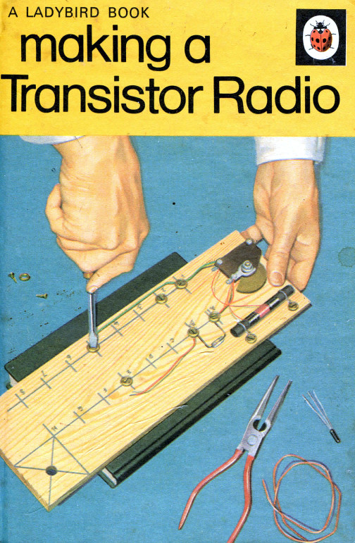
Contesting and disaster preparedness may leave me cold, but there’s magic in the minimal when it comes to radio. My introduction to electronics sometime in the 1970s came in the form of the simplest of radios, when my dad bought me a copy of George Dobbs’ Making A Transistor Radio, and showed me how to build a crystal set. That so few parts could form a working radio that pulled a signal from the air and into my headphones without the need for batteries was enough magic to get a 9-year-old me hooked.
Upgrading it to a germanium transistor regenerative receiver set me on the path that led me through university to an electronic engineering degree, and ultimately to writing here at Hackaday. There is in a very literal sense a whole world out there to be unlocked using radios made with relatively small bills-of-material, and though I’ve at times fumed about the tendency for such designs to be a little stuck-in-the-mud there is no reason why minimalist radios can not move with the times. That a quadrature front end for a sound-card SDR can be made from little more than a pile of 74-series chips is a particularly appealing example.
Scrap Televisions As The Gateway To RF Design
A UHF construction kit in every dumpster
I got my amateur radio licence back in the mists of time, when the UK’s Department of Trade and Industry only handed out two types of document. There was the class A licence or the Class B, with the difference being that for the former you had to pass a Morse test but got access to the HF bands while for the latter you had no Morse but were restricted to 144MHz and above. Thus the old men could talk in peace about The War on 80 metres, and the 2 metre band was a lively place.
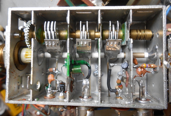
I had zero interest in Morse so I had a Class B licence, and since radio construction was my passion then as now I set about building for the VHF and UHF bands. I didn’t have a grown-up’s budget so my component supply was limited to what I could pull from scrap consumer electronics, which meant abundant 1970s PAL TV sets and the occasional earlier-model video recorder. There were plentiful VHF-capable inductors and transistors, and every TV tuner and VCR modulator had a set of UHF-capable transistors, so both the 2 metre and 70 cm bands were within my grasp.
There’s a sensible point among all this reminiscing, and it came in a thorough grounding in RF design techniques. RF is seen as a Dark Art by many engineers, and while there are certainly elements of design at these frequencies that edge into the complex it remains true that once you have a feel for the basics it’s something that’s easily possible to master. When you learn about stripline circuits by assembling them from copper wire and tinplate you learn a lot about shielding, impedances, routing, and interactions between neighbouring circuitry. Sure, it’s easy to make mistakes, but in that medium with a soldering iron it’s equally easy to try alternative designs until performance improves. So much UHF and higher RF circuitry is now packed into the silicon that the type of transistor circuits I was messing about with has become rather obsolete and your UHF work is much more likely to be on a PCB than a piece of tinplate, but the same principles apply. I miss those BF180 RF amplifier transistors from scrap 1970s TV sets.
The SDR As A Digital Playground
The age of the homebrew RF tinkerer may be at a close, at least in the manner in which I started it. Nobody at the cutting edge of radio is likely to be messing around with discrete transistor circuits in the 2020s, unless perhaps they are working with extremely exotic devices up in the millimetre wavelengths.It’s all software-defined radios, opaque black plastic boxes that deliver a useful radio experience on a computer but that’s it. No more homebrew, no more tinkering.
This would have taken a long time to build and get right as physical components.
You might well agree with the previous paragraph, but SDRs provide me with another of my favourite things about radio, namely that using GNU Radio I now have a general purpose digital signal processing playground. Coupled with a dirt-cheap RTL-SDR stick it gives me the ability to play with all the same building blocks I used to with my soldering iron and many more, at lightning speed in my computer. I can make a radio in no time, and change its parameters at will! The best part is though that it’s not simply restricted to radio. GNU radio works at whatever frequency can be digitised by its input device, and if that happens to be an audio card then it can work with audio too. Most readers last April Fools’ day probably spotted my fake gold USB cable a mile away, but perhaps fewer understood that the simple audio analyser in GNU Radio was completely real. It was inspired by a Supercon talk from Mike Ossmann and Kate Temkin, and if you didn’t see that talk I suggest you give it a watch.
So yes, there’s plenty in amateur radio that interests other radio amateurs but has never interested me, and there are still some aspects of the hobby that can be justifiably criticised. But amateur radio is a very broad church indeed, and above you’ve seen some of the things that keep me interested in it. Now it’s your turn, tell us in the comments: what radios do it for you?
Hackaday has among its staff a significant number of writers who also hold amateur radio licenses. We’re hardware folks at heart, so we like our radios homebrew, and we’re never happier than when we’re working at high frequencies.
Amateur radio is a multi-faceted hobby, there’s just so much that’s incredibly interesting about it. It’s a shame then that as a community we sometimes get bogged down with negativity when debating the minutia. So today let’s talk about a few of my favourite things about the hobby of amateur radio. I hope that you’ll find them interesting and entertaining, and in turn share your own favorite things in the comments below.
Homebrew Radios Of The Minimal Kind
This book was where it all started for me.
Contesting and disaster preparedness may leave me cold, but there’s magic in the minimal when it comes to radio. My introduction to electronics sometime in the 1970s came in the form of the simplest of radios, when my dad bought me a copy of George Dobbs’ Making A Transistor Radio, and showed me how to build a crystal set. That so few parts could form a working radio that pulled a signal from the air and into my headphones without the need for batteries was enough magic to get a 9-year-old me hooked.
Upgrading it to a germanium transistor regenerative receiver set me on the path that led me through university to an electronic engineering degree, and ultimately to writing here at Hackaday. There is in a very literal sense a whole world out there to be unlocked using radios made with relatively small bills-of-material, and though I’ve at times fumed about the tendency for such designs to be a little stuck-in-the-mud there is no reason why minimalist radios can not move with the times. That a quadrature front end for a sound-card SDR can be made from little more than a pile of 74-series chips is a particularly appealing example.
Scrap Televisions As The Gateway To RF Design
A UHF construction kit in every dumpster
I got my amateur radio licence back in the mists of time, when the UK’s Department of Trade and Industry only handed out two types of document. There was the class A licence or the Class B, with the difference being that for the former you had to pass a Morse test but got access to the HF bands while for the latter you had no Morse but were restricted to 144MHz and above. Thus the old men could talk in peace about The War on 80 metres, and the 2 metre band was a lively place.
I had zero interest in Morse so I had a Class B licence, and since radio construction was my passion then as now I set about building for the VHF and UHF bands. I didn’t have a grown-up’s budget so my component supply was limited to what I could pull from scrap consumer electronics, which meant abundant 1970s PAL TV sets and the occasional earlier-model video recorder. There were plentiful VHF-capable inductors and transistors, and every TV tuner and VCR modulator had a set of UHF-capable transistors, so both the 2 metre and 70 cm bands were within my grasp.
There’s a sensible point among all this reminiscing, and it came in a thorough grounding in RF design techniques. RF is seen as a Dark Art by many engineers, and while there are certainly elements of design at these frequencies that edge into the complex it remains true that once you have a feel for the basics it’s something that’s easily possible to master. When you learn about stripline circuits by assembling them from copper wire and tinplate you learn a lot about shielding, impedances, routing, and interactions between neighbouring circuitry. Sure, it’s easy to make mistakes, but in that medium with a soldering iron it’s equally easy to try alternative designs until performance improves. So much UHF and higher RF circuitry is now packed into the silicon that the type of transistor circuits I was messing about with has become rather obsolete and your UHF work is much more likely to be on a PCB than a piece of tinplate, but the same principles apply. I miss those BF180 RF amplifier transistors from scrap 1970s TV sets.
The SDR As A Digital Playground
The age of the homebrew RF tinkerer may be at a close, at least in the manner in which I started it. Nobody at the cutting edge of radio is likely to be messing around with discrete transistor circuits in the 2020s, unless perhaps they are working with extremely exotic devices up in the millimetre wavelengths.It’s all software-defined radios, opaque black plastic boxes that deliver a useful radio experience on a computer but that’s it. No more homebrew, no more tinkering.
This would have taken a long time to build and get right as physical components.
You might well agree with the previous paragraph, but SDRs provide me with another of my favourite things about radio, namely that using GNU Radio I now have a general purpose digital signal processing playground. Coupled with a dirt-cheap RTL-SDR stick it gives me the ability to play with all the same building blocks I used to with my soldering iron and many more, at lightning speed in my computer. I can make a radio in no time, and change its parameters at will! The best part is though that it’s not simply restricted to radio. GNU radio works at whatever frequency can be digitised by its input device, and if that happens to be an audio card then it can work with audio too. Most readers last April Fools’ day probably spotted my fake gold USB cable a mile away, but perhaps fewer understood that the simple audio analyser in GNU Radio was completely real. It was inspired by a Supercon talk from Mike Ossmann and Kate Temkin, and if you didn’t see that talk I suggest you give it a watch.
So yes, there’s plenty in amateur radio that interests other radio amateurs but has never interested me, and there are still some aspects of the hobby that can be justifiably criticised. But amateur radio is a very broad church indeed, and above you’ve seen some of the things that keep me interested in it. Now it’s your turn, tell us in the comments: what radios do it for you?
Hackaday has among its staff a significant number of writers who also hold amateur radio licenses. We’re hardware folks at heart, so we like our radios homebrew, and we’re never happier than when we’re working at high frequencies.
Amateur radio is a multi-faceted hobby, there’s just so much that’s incredibly interesting about it. It’s a shame then that as a community we sometimes get bogged down with negativity when debating the minutia. So today let’s talk about a few of my favourite things about the hobby of amateur radio. I hope that you’ll find them interesting and entertaining, and in turn share your own favorite things in the comments below.
Homebrew Radios Of The Minimal Kind
This book was where it all started for me.
Contesting and disaster preparedness may leave me cold, but there’s magic in the minimal when it comes to radio. My introduction to electronics sometime in the 1970s came in the form of the simplest of radios, when my dad bought me a copy of George Dobbs’ Making A Transistor Radio, and showed me how to build a crystal set. That so few parts could form a working radio that pulled a signal from the air and into my headphones without the need for batteries was enough magic to get a 9-year-old me hooked.
Upgrading it to a germanium transistor regenerative receiver set me on the path that led me through university to an electronic engineering degree, and ultimately to writing here at Hackaday. There is in a very literal sense a whole world out there to be unlocked using radios made with relatively small bills-of-material, and though I’ve at times fumed about the tendency for such designs to be a little stuck-in-the-mud there is no reason why minimalist radios can not move with the times. That a quadrature front end for a sound-card SDR can be made from little more than a pile of 74-series chips is a particularly appealing example.
Scrap Televisions As The Gateway To RF Design
A UHF construction kit in every dumpster
I got my amateur radio licence back in the mists of time, when the UK’s Department of Trade and Industry only handed out two types of document. There was the class A licence or the Class B, with the difference being that for the former you had to pass a Morse test but got access to the HF bands while for the latter you had no Morse but were restricted to 144MHz and above. Thus the old men could talk in peace about The War on 80 metres, and the 2 metre band was a lively place.
I had zero interest in Morse so I had a Class B licence, and since radio construction was my passion then as now I set about building for the VHF and UHF bands. I didn’t have a grown-up’s budget so my component supply was limited to what I could pull from scrap consumer electronics, which meant abundant 1970s PAL TV sets and the occasional earlier-model video recorder. There were plentiful VHF-capable inductors and transistors, and every TV tuner and VCR modulator had a set of UHF-capable transistors, so both the 2 metre and 70 cm bands were within my grasp.
There’s a sensible point among all this reminiscing, and it came in a thorough grounding in RF design techniques. RF is seen as a Dark Art by many engineers, and while there are certainly elements of design at these frequencies that edge into the complex it remains true that once you have a feel for the basics it’s something that’s easily possible to master. When you learn about stripline circuits by assembling them from copper wire and tinplate you learn a lot about shielding, impedances, routing, and interactions between neighbouring circuitry. Sure, it’s easy to make mistakes, but in that medium with a soldering iron it’s equally easy to try alternative designs until performance improves. So much UHF and higher RF circuitry is now packed into the silicon that the type of transistor circuits I was messing about with has become rather obsolete and your UHF work is much more likely to be on a PCB than a piece of tinplate, but the same principles apply. I miss those BF180 RF amplifier transistors from scrap 1970s TV sets.
The SDR As A Digital Playground
The age of the homebrew RF tinkerer may be at a close, at least in the manner in which I started it. Nobody at the cutting edge of radio is likely to be messing around with discrete transistor circuits in the 2020s, unless perhaps they are working with extremely exotic devices up in the millimetre wavelengths.It’s all software-defined radios, opaque black plastic boxes that deliver a useful radio experience on a computer but that’s it. No more homebrew, no more tinkering.
This would have taken a long time to build and get right as physical components.
You might well agree with the previous paragraph, but SDRs provide me with another of my favourite things about radio, namely that using GNU Radio I now have a general purpose digital signal processing playground. Coupled with a dirt-cheap RTL-SDR stick it gives me the ability to play with all the same building blocks I used to with my soldering iron and many more, at lightning speed in my computer. I can make a radio in no time, and change its parameters at will! The best part is though that it’s not simply restricted to radio. GNU radio works at whatever frequency can be digitised by its input device, and if that happens to be an audio card then it can work with audio too. Most readers last April Fools’ day probably spotted my fake gold USB cable a mile away, but perhaps fewer understood that the simple audio analyser in GNU Radio was completely real. It was inspired by a Supercon talk from Mike Ossmann and Kate Temkin, and if you didn’t see that talk I suggest you give it a watch.
So yes, there’s plenty in amateur radio that interests other radio amateurs but has never interested me, and there are still some aspects of the hobby that can be justifiably criticised. But amateur radio is a very broad church indeed, and above you’ve seen some of the things that keep me interested in it. Now it’s your turn, tell us in the comments: what radios do it for you?
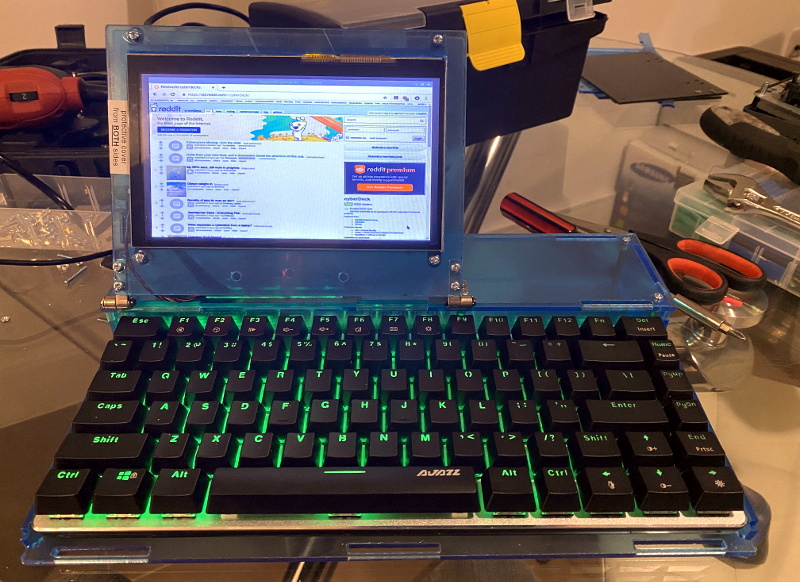
For those who decide to build their own personal cyberdeck, it’s often as much about the journey as it is the final product. The recent write-up that [mickwheelz] put together about the process that lead him to build his own bespoke mobile computer is a perfect example. He went through three distinct design phases to create something that had what he describes as a “retro-futuristic, hand-built, utilitarian aesthetic”, and we think you’ll agree the final product is right on target.
At Hackaday we’re strong believers that you can learn just as much from a failed attempt as you will from a rousing success, which is why we especially appreciate the way [mickwheelz] has documented this project. The basic layout and general bill of materials for his hypothetical cyberdeck had been sorted out in his head for about a year, but it took a few attempts until everything came together in a way he was happy with. Rather than pretend those early missteps never happened, he’s decided to present each one and explain why it didn’t quite work out.
This laser-cut acrylic design was difficult to assemble.
Frankly both of his earlier attempts look pretty slick to us, but of course the only person who’s opinion really counts when it comes to a good cyberdeck is the one who’s building it. The original acrylic design was a bit too fiddly, and while his first attempt at 3D printing the computer’s frame and enclosure went much better, it still left something to be desired.
The final result is a clean and straightforward design that has plenty of room inside for a Raspberry Pi 4, UPSPack V3 power management board, 10,000 mAh battery, internal USB hub, and a AK33 mechanical keyboard. Topside there’s a 7” 1024×600 IPS LCD with touch overlay that’s naturally been offset in the traditional cyberdeck style, and on the right side of the enclosure there’s a bay that holds a KKMoon RTL-SDR. Though that could certainly be swapped out for something else should you decide to print out your own version of this Creative Commons licensed design.
Most of our 3D printers lay down molten plastic or use photosensitive resin. But professional printers often use metal powder, laying out a pattern and then sintering it with a laser. [Metal Matters] is trying to homebrew a similar system (video, embedded below). And while not entirely successful, the handful of detailed progress videos are interesting to watch. We particularly enjoyed the latest installment (the second video, below) which showed solutions to some of the problems.
Because of the complexity of the system, there are small tidbits of interest even if you don’t want to build a metal printer. For example, in the most recent video, a CCD camera gives up its sensor to detect the laser’s focus.
Before you get the idea to try this with your cheap Chinese laser cutter, you should know that you’re going to have to splash out for some more lasers — the NUBM31 laser array from a laser projector has 20 diodes, each producing about 4.75 watts output.
Not that we haven’t seen laser cutters used as 3D printers, though. We hear a 5 W laser is good enough to work with nylon. We realize [Metal Matters] has some work left to do, but we have a feeling it is going to work out in the end and we can’t wait to see the success video.
Raspberry Pi was synonymous with single-board Linux computers. No longer. The $4 Raspberry Pi Pico board is their attempt to break into the crowded microcontroller module market.
The microcontroller in question, the RP2040, is also Raspberry Pi’s first foray into custom silicon, and it’s got a dual-core Cortex M0+ with luxurious amounts of SRAM and some very interesting custom I/O peripheral hardware that will likely mean that you never have to bit-bang again. But a bare microcontroller is no fun without a dev board, and the Raspberry Pi Pico adds 2 MB of flash, USB connectivity, and nice power management.
As with the Raspberry Pi Linux machines, the emphasis is on getting you up and running quickly, and there is copious documentation: from “Getting Started” type guides for both the C/C++ and MicroPython SDKs with code examples, to serious datasheets for the Pico and the RP2040 itself, to hardware design notes and KiCAD breakout boards, and even the contents of the on-board Boot ROM. The Pico seems designed to make a friendly introduction to microcontrollers using MicroPython, but there’s enough guidance available for you to go as deep down the rabbit hole as you’d like.
Our quick take: the RP2040 is a very well thought-out microcontroller, with myriad nice design touches throughout, enough power to get most jobs done, and an innovative and very hacker-friendly software-defined hardware I/O peripheral. It’s backed by good documentation and many working examples, and at the end of the day it runs a pair of familiar ARM MO+ CPU cores. If this hits the shelves at the proposed $4 price, we can see it becoming the go-to board for many projects that don’t require wireless connectivity.
But you want more detail, right? Read on.
The Specs and the Luxuries
In many ways, the Pico is a well-appointed “normal” microcontroller board. It has 26 3.3 V GPIOs, a standard ARM Serial Wire Debug (SWD) port, USB host or device capabilities, two UARTs, two I2Cs, two SPIs, and 16 PWM channels in eight groups. (The PWM unit can also measure incoming PWM signals, both their frequency and duty cycle.) The Pico has a 12-bit ADC, although it’s connected to only four pins, so you’ve got to be a little careful there.
The twin ARM M0+ cores run off of PLLs, and are specced up to 133 MHz, which is pretty fast. There are separate clock dividers for nearly every peripheral, and they can be turned on and off individually for power savings, as with most other ARM microcontrollers. It runs full-out at around 100 mA @ 5 V, and has full-memory-retention sleep modes under 1 mA.
As the ESP8266 and ESP32 modules do, it uses external flash ROM to store programs, and can run code directly from the flash as if it were internal memory. The Pico board comes with a decent 2 MB QSPI flash chip, but if you’re handy with a soldering iron, you can fit up to 16 MB. It has 264 kB of SRAM, which is certainly comfy. The RAM is divided up internally into four striped 64 kB banks for fast parallel access, but they’re also accessible singly if you’d like. Two additional 4 kB banks are non-striped and suggest using themselves as per-core stack memory, but nothing forces you to use them that way either.
There are numerous minor hardware-level conveniences. All of the configuration registers are 32 bits wide, and so you might not want to have to specify all of them, or maybe you want to avoid the read-modify-write dance. Like many of the STM32 chips, there is a special memory map that lets you set, clear, or XOR any bit in any of the config registers in a single atomic command. There are also 30 GPIOs, so they all fit inside a single 32-bit register — none of this Port B, Pin 7 stuff. This also means that you can read or write them all at once, while setting individual pins is easy through the above atomic access.
An internal mask ROM contains the UF2 bootloader, which means that you can always get the chip back under control. When you plug the Pico in holding down the BOOTSEL button, it shows up as a USB mass storage device, and you can just copy your code across, with no programmer, and Raspberry even provides an all-zeros file that you can copy across to completely clean-slate the machine. If you copy the Pico’s MicroPython binary across, however, you’ll never need the bootloader again. The mask ROM also contains some fast routines that support integer and floating point math, and all of the contents are open source as mentioned above.
The power regulation onboard is a boost-buck configuration that takes an input from 1.8 V to 5 V. This is a good range for lithium batteries, for instance, which can be a hassle because they run both above and below the IC’s 3.3 V, so it’s nice to have a boost-buck regulator to squeeze out the last few milliamp-hours. Or you could run your project on two AAs. That’s nice.
So the Pico/RP2040 is a competent modern dev board with some thoughtful touches. But it gets better.
The PIO: Never Bitbang Again
The real standout peripheral on the RP2040 and the Pico is the Programmable I/O (PIO) hardware, which allows you to define your own digital communication peripheral. There are two of these PIO units, and each one has four programmable state machines that run sequential programs written in a special PIO assembly language. Each of the state machines has its own clock divider, register memory, IRQ flags, DMA interface, and GPIO mapping. These allow essentially arbitrary cycle-accurate I/O, doing the heavy lifting so that the CPU doesn’t have to.
If you want to program another UART, for instance, it’s trivial. But so is Manchester-encoded UART, or a grey code encoder/decoder, or even fancier tricks. One of the example applications is a DPI video example, with one state machine handling the scanline timing and pixel clock, while another pushes out the pixel data and run-length encodes it. These are the sort of simple-but-fast duties that can bog down a CPU, leading to timing glitches, so dedicated hardware is the right solution.
The PIOs are meant to have a lot of the flexibility of a CPLD or FPGA, but be easier to program. Each state machine can only take a “program” that is 32 instructions long, but the “pioasm” language is very dense. For instance, the command to set pin states also has an argument that says how long to wait after the pins are set, and additional “side-set” pins can be twiddled in the same instruction. So with one instruction you can raise a clock line, set up your data, and hold this state for a defined time. A basic SPI master TX implementation is two lines.
Or take the example of the WS2812 LED protocol. To send a logical 1, you hold the self-clocked data line high for a long period and low for a short period. To send a logical 0, the data line is held high for a short period and low for a long one. Creating the routines to do this with reasonable speed in the CPU, without glitches, required a non-trivial shedding of hacker tears. With the PIO peripheral, writing a routine to shift out these bits with absolute cycle accuracy is simple, and once that’s done your code can simply write RGB values to the PIO and the rest is taken care of.
To run PIO code from C, the assembler is called at compile time, the program is turned into machine language and stored as a matrix in a header file, and then this can be written to the PIO device from within main() to initialize it. In Python, it’s even easier — the @asm_pio decorator turns a function into PIO code. You just have to write the “Python” function using the nine PIO assembly instructions and then hook it up to GPIO pins. After that, you can call it from your code as if it were a normal peripheral.
Having played around with it only a little bit, the PIO is the coolest feature of the Pico/RP2040. It’s just a little bit of cycle-correct programmable logic, but most of the time, that’s all you need. And if you don’t feel like learning a new assembly language — although it’s only nine instructions — there are a heaping handful of examples already, and surely folks will develop more once the boards hit the streets.
IDEs and SDKs: C and MicroPython
The Raspberry Pi single-board computers (SBCs), when combined with their documentation and examples, usually manage a nice blend of being simple enough for the newbie while at the same time not hiding too much. The result is that, rather than having the underlying system’s Linuxiness abstracted away, you get introduced to it in a friendly way. That seems to be what the Raspberries are aiming at with the Pico — an introduction to microcontrollers that’s made friendly through documentation and MicroPython’s ease of use, but that’s also not pulling any punches when you turn to look at the C/C++ code.
USB for power, UART for communication, and SWD for programming and debugging.
And having a Raspberry Pi SBC on hand makes a lot of the most hardcore microcontrollering simpler. For instance, if you want to do debugging on-chip, you’ll need to connect over the SWD interface, and for that you usually need a programmer. But of course, you can also bit-bang a SWD controller with the GPIOs of a Raspberry Pi SBC, but you’ll have to configure OpenOCD just right to do so.
If that all sounded like gibberish, don’t worry — all of this is taken care of by a simple pico_setup.sh script. It not only installs all of the compilation and debugging environment, it also (optionally) pulls down VScode for you. Nice.
And you will want to program it over the SWD eventually. The cycle of unplugging USB, holding down a button, and re-plugging USB gets old real fast.
If you’re a command-line junkie, the C SDK’s build system is based on CMake and runs just fine from the command line if you’ve already got the ARM toolchain installed. And as with all SDKs, there’s a certain amount of boilerplate necessary to start up a new coding session. This is taken care of by the pico project generator, so you don’t have to.
In the “Getting started” guides, you’ll find instructions for setting up your environment on a Raspberry Pi SBC, Windows, Mac, or desktop Linux machine. If you prefer Eclipse as an IDE, there are integration instructions as well.
Two Cores: Here be Dragons
If there’s one area that strikes me as not yet fully developed, it’s the dual-core aspect of the system. Right now, if you write either C or Python code, it’s running on Core 0, while Core 1 is simply sitting idle. Both the C and Python SDK documentation tell you how to start up a thread on the other core, and there’s example code available as well, but the instructions are sparse. In C, there’s a pico/multicore.h and even mutex, semaphore, and queue libs for you to include, but the documentation warns that most of the stdlib functions aren’t thread-safe. In Python you import _thread and call the start_new_thread() method, but I don’t know how much fine-grained control you have.
If all of the above sounds scary, well, it is a little. The truth about coding for multiprocessor systems is that it opens up new ways for things to go wrong, as one CPU changes values out from under the other, or they both try to write out to the UART at the same time. We wrote the Raspberries and asked if they were planning to port over an RTOS, which provides a little more structure to the problem, and they replied that that was actually first on their plate after they get through the release. So unless you know what you’re doing, you might not get the full benefit of the dual-core chip just yet. But we’re honestly looking forward to an RTOS getting the Raspberry Pi documentation-and-tutorial treatment when it happens.
Deep Thoughts
It’s not every day that you see a new player enter the microcontroller market, let alone one with the hacker-friendly qualifications of Raspberry Pi. For that alone, this board is notable. But the feature set is also solid, there are many creature comforts in both the silicon and the support, and it brings one truly new capability to the table in the form of the PIO units. Add to all this a price tag of $4, and you can imagine it becoming folks’ go-to board — for those times when you don’t need wireless connectivity.
Indeed, the only real competitor for this board in terms of price/performance ratio are the various ESP32 boards. But they’re also very different animals — one offers fewer GPIOs but has extensive wireless features, and the other has more (and more flexible) GPIO, device and host USB, but no radio. Power consumption while running full-out, with wireless turned off, is a slight advantage for the ESP32, but the sleep modes of the Pico are slightly thriftier. Both SDKs get the job done in C, and both run MicroPython. ESP32’s dual cores run FreeRTOS, but we imagine it won’t be very long before that playing field is levelled. So basically it’s down to WiFi vs USB.
Of course, for slightly less money, one can pick up one of the STM32-based “Black Pill” boards, with yet another set of pros and cons. Choices, choices!
With the Pico, Raspberry Pi is entering a crowded field. They’ve got the name recognition, a cool hardware trick, a great value proposition, and a track record of solid documentation. If I were coding up a GPIO-heavy application without the need for wireless, the Pico would be a solid choice, especially if I could make use of the extra core.
I’ll leave you with a teaser: On page 9 of the RP2040 datasheet, they lay out what “2040” stands for: two cores, type M0+, more than 256 kB RAM, and zero kB flash. Does that mean we’ll eventually see models with more RAM, onboard flash, or different ARM cores? RP2050? RP2048? Speculate wildly in the comments.
Let’s be honest, building a home arcade cabinet isn’t exactly the challenge it once was. There’s plenty of kits out there that do all the hard work for you, and they even sell some pretty passable turn-key units at Walmart now. If you want to put a traditional arcade cabinet in your home, it’s not hard to get one.
Which is why this wild build by [Rafael Rubio] is so interesting. The entirely 3D printed enclosure looks like some kind of art piece from the 1970s, and is a perfect example of the kind of unconventional designs made possible by low-cost additive manufacturing. Building something like this out of wood or metal would be nightmare, especially for the novice; but with even a relatively meager desktop 3D printer you’re only a few clicks away from running off your own copy.
Removable side panels allow access to the electronics.
Inside the nautilus-like enclosure is a Raspberry Pi running Retropie, a 10″ LCD panel from Pimoroni, and a GeeekPi interface board that connects up to the 8-way joystick and arcade buttons. [Rafael] has included a Bill of Materials and an assembly overview that you can follow along with, though the cavernous internal dimensions of the enclosure certainly give you ample of room for improvisation if you’d rather blaze your own path.
Like the retro-futuristic computer terminals created by [Oriol Ferrer Mesià], this arcade machine completely reinvents a traditional design that most people take for granted. Is this layout actually better than the standard arcade cabinet? It’s not really our place to say. But it’s certainly a new and unconventional approach to “solved” problem, and that’s what we’re all about.
What attracts a lot of people to amateur radio is that it gives you the ability to make your own gear. Scratch-building hams usually start by making their own antennas, but eventually, the itch to build one’s own radio must be scratched. And building this one-transistor transmitter is just about the simplest way to dive into the world of DIY radio.
Of course, limiting yourself to eight components in total entails making some sacrifices, and [Kostas (SV3ORA)]’s transmitter is clearly a study in compromise. For starters, it’s only a transmitter, so you’ll need to make other arrangements to have a meaningful conversation. You’ll also have to learn Morse code because the minimalist build only supports continuous-wave (CW) mode, although it can be modified for amplitude modulation (AM) voice work.
The circuit is flexible enough that almost any part can be substituted and the transmitter will still work. Most of the parts are junk-bin items, although the main transformer is something you’ll have to wind by hand. As described, the transformer not only provides feedback to the transistor oscillator, but also has a winding that powers an incandescent pilot lamp, and provides taps for attaching antennas of different impedances — no external tuner needed. [SV3ORA] provides detailed transformer-winding instructions and shows the final build, which looks very professional and tidy. The video below shows the rig in action with a separate receiver providing sidetone; there’s also the option of using one of the WebSDR receivers sprinkled around the globe to verify you’re getting out.
This little transmitter looks like a ton of fun to build, and we may just try it for our $50 Ham series if we can find all the parts. Honestly, the hardest to come by might be the variable capacitor, but there are ways around that too.
Nostalgia aside, there are a few things an analog scope can still do better than a digital, with oscilloscope art being a prime example. The blue-green glow of phosphors in a real CRT just add something special to such builds, and as a practitioner of this craft, [Aaron Stokes], aka [Oscilloboy], decided to paint a New Year’s affirmation on his oscilloscope screen, in Japanese calligraphy of all things.
When used in X-Y mode, analog oscilloscopes lend themselves nicely to vector-based graphics, which is the approach [Aaron] has taken with previous “Oscilloclock” builds, like the Metropolis Clock. The current work, however, doesn’t use vector graphics, opting instead to turn the scope into the business end of a VGA display. He had previously developed the hardware needed to convert a VGA signal into X- and Y-axis analog outputs, so the bulk of the work was rendering the calligraphy, first in ink and then scanning and processing the results into a file. In keeping with the Japanese theme, [Aaron] chose a rare scope from Nihon Tsushinki Co., Ltd., from 1963. It’s a beautiful piece of equipment and obviously lovingly restored, and with the VGA adapter temporarily connected, the four Japanese characters scroll gracefully up the screen, delivering the uplifting message: “Steady progress, day by day.”
I’m always fascinated that someone designed just about everything you use, no matter how trivial it is. The keyboard you type on, the light switch you turn on, even the faucet handle. They don’t just spontaneously grow on trees, so some human being had to build it and probably had at least a hazy design in mind when they started it.
Some things are so ubiquitous that it is hard to remember that someone had to dream them up to begin with. A friend of mine asked me the other day why we use Control+X and Control+V to manipulate the clipboard almost universally. Control+C for copy makes sense, of course, but it is still odd that it is virtually universal in an industry where everyone likes to reinvent the wheel. I wasn’t sure of the answer but figured it had to do with some of the user interface standards from IBM or Sun. Turns out, it is much older than that.
Back When CTRL-C Only Meant Break
If you recall, though, Control+C hasn’t always been synonymous with copy. Control+C was well known as a break command in TOPS-10, CP/M, MSDOS, and several other systems. This might have been because C was for “cancel” or it could be because the ASCII for “end text” is Control+C. So I knew there was some point in relatively recent history where the control keys took over the world.
Then again, the clipboard itself isn’t that old and it also needed inventing. Pentti Kanerva, from Stanford, was using delete buffers to hold text for later, a technique that caught the attention of Larry Tesler. Larry worked for Xerox PARC — the people who more or less invented the graphical user interface. In the book, Designing Interactions by Bill Moggridge, there is mention that the team was already working on cut and paste of elements as part of a desktop publishing application for Ginn and Company, and they knew of Kanerva’s work. It was a natural idea to extend the cut and paste concept to text.
Early PARC
The only problem with the original system was the wording of “delete” sounded too permanent. Early PARC software sent deleted things to a trashcan and set cut things to a wastebin. Talk about confusing. The new cut and paste metaphor also used fewer keys than Kanerva’s system.
It may seem obvious now, but the right way to move text around was highly debatable back then. While some designers favored the cut/copy/paste method we have now, others wanted a move/copy/delete/transpose. This is more akin to how some older systems like WordStar did things. The commands operated on a block of text on the screen with no intermediate step. Even the ideas of putting the cursor between letters, the shape of the cursor was not obvious at the time.
The Xerox Alto was ahead of its time and it offered a graphical text editor, Gypsy. This 1975 word processor did allow cut and paste as we know it. However, the commands used the Escape key. As far as I can tell, the actual control commands we think of today originated with the Apple Human Interface Standard.
The Apple Standard
Bruce Tognazzini, otherwise known as Tog, was an early and influential Apple employee and wrote much of the original standard for the 1984 Macintosh. However, there were many people involved and you can catch a video of Larry Tesler and others discussing the early history of Apple GUI and the PARC influence on it, below.
According to the video, the team knew that people would use cut, paste, copy, and undo quite a bit and they wanted a standard way to do that across applications. The official story is that C was for copy, X looks like a crossout or a pair of scissors, and V looks like an insertion mark. The Z just happens to be the next character in that cluster–we might well have had Control+B as undo.
It is hard to remember, but Apple didn’t always set market direction. IBM’s Common User Access (CUA) standard came out in 1987 and — not wanting to conflict with Control+C as a break character — defined different characters for cut, copy, and paste. This was three years after the Apple document and early versions of Windows used these keys. However, the Control+C,V,X trinity was so prevalent, that Windows eventually allowed both sets of characters. Today, programs like emacs support CUA mode which allows for Control+C,V,X even though those weren’t in the original CUA standard.
Unix would see a similar effort to standardize on the Common Desktop Environment as part of the Common Open Software Environment in 1993, nine years after the Apple document. By that time, most programs had already adopted what we think of as normal keystrokes.
Our Designs
Today it seems only natural how the clipboard works and the keystrokes you use. Programs that buck this trend — I’m looking at Eagle — take a lot of flack for making you pick a command like copy and then making a selection.
Still, I’m struck by how many times a casual decision winds up becoming a big thing. Which way do electrons flow? How many buttons should a mouse have? To their credit, the Apple team seemed to understand that even tiny decisions could become a big deal and they put a lot of thought into things.
What causal decision will you make this week that will have a far-reaching impact? Most of us won’t get a chance to set the keystrokes used by everyone on the planet. But how many times have you written a quick shell script that turns into something used for years, or made up a quick cable that becomes a permanent part of a lab setup? Something to think about before your next causal hack.
I’m always fascinated that someone designed just about everything you use, no matter how trivial it is. The keyboard you type on, the light switch you turn on, even the faucet handle. They don’t just spontaneously grow on trees, so some human being had to build it and probably had at least a hazy design in mind when they started it.
Some things are so ubiquitous that it is hard to remember that someone had to dream them up to begin with. A friend of mine asked me the other day why we use Control+X and Control+V to manipulate the clipboard almost universally. Control+C for copy makes sense, of course, but it is still odd that it is virtually universal in an industry where everyone likes to reinvent the wheel. I wasn’t sure of the answer but figured it had to do with some of the user interface standards from IBM or Sun. Turns out, it is much older than that.
Back When CTRL-C Only Meant Break
If you recall, though, Control+C hasn’t always been synonymous with copy. Control+C was well known as a break command in TOPS-10, CP/M, MSDOS, and several other systems. This might have been because C was for “cancel” or it could be because the ASCII for “end text” is Control+C. So I knew there was some point in relatively recent history where the control keys took over the world.
Then again, the clipboard itself isn’t that old and it also needed inventing. Pentti Kanerva, from Stanford, was using delete buffers to hold text for later, a technique that caught the attention of Larry Tesler. Larry worked for Xerox PARC — the people who more or less invented the graphical user interface. In the book, Designing Interactions by Bill Moggridge, there is mention that the team was already working on cut and paste of elements as part of a desktop publishing application for Ginn and Company, and they knew of Kanerva’s work. It was a natural idea to extend the cut and paste concept to text.
Early PARC
The only problem with the original system was the wording of “delete” sounded too permanent. Early PARC software sent deleted things to a trashcan and set cut things to a wastebin. Talk about confusing. The new cut and paste metaphor also used fewer keys than Kanerva’s system.
It may seem obvious now, but the right way to move text around was highly debatable back then. While some designers favored the cut/copy/paste method we have now, others wanted a move/copy/delete/transpose. This is more akin to how some older systems like WordStar did things. The commands operated on a block of text on the screen with no intermediate step. Even the ideas of putting the cursor between letters, the shape of the cursor was not obvious at the time.
The Xerox Alto was ahead of its time and it offered a graphical text editor, Gypsy. This 1975 word processor did allow cut and paste as we know it. However, the commands used the Escape key. As far as I can tell, the actual control commands we think of today originated with the Apple Human Interface Standard.
The Apple Standard
Bruce Tognazzini, otherwise known as Tog, was an early and influential Apple employee and wrote much of the original standard for the 1984 Macintosh. However, there were many people involved and you can catch a video of Larry Tesler and others discussing the early history of Apple GUI and the PARC influence on it, below.
According to the video, the team knew that people would use cut, paste, copy, and undo quite a bit and they wanted a standard way to do that across applications. The official story is that C was for copy, X looks like a crossout or a pair of scissors, and V looks like an insertion mark. The Z just happens to be the next character in that cluster–we might well have had Control+B as undo.
It is hard to remember, but Apple didn’t always set market direction. IBM’s Common User Access (CUA) standard came out in 1987 and — not wanting to conflict with Control+C as a break character — defined different characters for cut, copy, and paste. This was three years after the Apple document and early versions of Windows used these keys. However, the Control+C,V,X trinity was so prevalent, that Windows eventually allowed both sets of characters. Today, programs like emacs support CUA mode which allows for Control+C,V,X even though those weren’t in the original CUA standard.
Unix would see a similar effort to standardize on the Common Desktop Environment as part of the Common Open Software Environment in 1993, nine years after the Apple document. By that time, most programs had already adopted what we think of as normal keystrokes.
Our Designs
Today it seems only natural how the clipboard works and the keystrokes you use. Programs that buck this trend — I’m looking at Eagle — take a lot of flack for making you pick a command like copy and then making a selection.
Still, I’m struck by how many times a casual decision winds up becoming a big thing. Which way do electrons flow? How many buttons should a mouse have? To their credit, the Apple team seemed to understand that even tiny decisions could become a big deal and they put a lot of thought into things.
What causal decision will you make this week that will have a far-reaching impact? Most of us won’t get a chance to set the keystrokes used by everyone on the planet. But how many times have you written a quick shell script that turns into something used for years, or made up a quick cable that becomes a permanent part of a lab setup? Something to think about before your next causal hack.
Although it would be nice, we can’t all work from home. If you have to spend the day in close quarters with other people, you might want more protection than just a mask and sanitizer. Check out [jshanna]’s DIY HEPA filtering fan — it looks like a breeze to build and uses commonly-available parts plus a few 3D-printed pieces to put it all together.
The basis of this attractive and useful office must-have is a muffin fan from Amazon that has an optional variable speed controller. A long threaded rod runs up the center of the HEPA filter, so it attaches kind of like a lampshade. The fan draws up air from underneath and blows it upward through the filter and out into the room. Whenever the HEPA filter gets dirty, just take it out and wash it.
For many years now, the so-called ‘Blue Pill’ STM32 MCU development board has been a staple in the hobbyist community. Finding its origins as an apparent Maple Mini clone, the diminutive board is easily to use in breadboard projects thanks to its dual rows of 0.1″ pin sockets. Best of all, it only costs a few bucks, even if you can only really buy it via sellers on AliExpress and EBay.
Starting last year, boards with a black soldermask and an STM32F4 Access (entry-level) series MCUs including the F401 and F411 began to appear. These boards with the nickname ‘Black Pill’ or ‘Black Pill 2’. F103 boards also existed with black soldermask for a while, so it’s confusing. The F4xx Black Pills are available via the same sources as the F103-based Blue Pill ones, for a similar price, but feature an MCU that’s considerably newer and more powerful. This raises the question of whether it makes sense at this point to switch to these new boards.
Our answer is yes, but it’s not entirely clearcut. The newer hardware is better for most purposes, really lacking only the F103’s dual ADCs. But hardware isn’t the only consideration; depending on one’s preferred framework, support may be lacking or incomplete. So let’s take a look at what it takes to switch.
The Hardware
The F4 MCUs have significantly better specs than the F103, with a higher clockspeed, more flash storage and more SRAM. In total we have three MCUs to compare on the old and new boards:
The Cortex-M core in the F103 is the M3, whereas the F4xx has an M4 core. For the CPU side of the MCU this effectively means that in addition to higher clockspeeds we also get the ARMv7E-M ISA, instead of the ARMv7-M of the M3. This adds full saturation arithmetic instructions, DSP instructions and optional single-precision floating point instructions. Both the F401 and F411 have a single-point FP unit, and are thus much more suited for floating point arithmetic than the F103.
More detailed differences can be found when we look at Application Note 4904 (AN4904) from ST: Migration of microcontroller applications from STM32F1 Series to STM32F4 Access lines. This document summarizes all of the differences between the two MCU families worthy of note when migrating from one to the other, whether for the physical pin layout, peripherals or the bootloader.
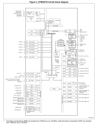
Here the biggest changes are probably in the memory layout, along with the number of certain types of peripherals. Feel free to compare along with us in the block diagrams.
A significant change between F103 and F4xx is that the GPIO peripherals were moved off the Advanced Peripheral Bus (APB) onto the AHB. AHB is the high-performance bus, for high bandwidth, low-latency operations. It is connected directly to the Cortex-M core via the AHB bus matrix. The APB on the other hand is a simpler bus, with no burst operations. Accessing peripherals on the APB from the Cortex-M core requires that the instructions pass over the AHB-to-APB bridge to the APB.
This should mean that GPIO operations are faster on the F4xx MCUs, especially with high-frequency operations. In addition, the I/O pin multiplexing on the F4xx MCUs changed to only allow one alternate function (AF) to be defined for a single GPIO pin. This corresponds to the integration of AF registers in the GPIO peripheral.
A big change is also seen in the RTC peripheral, which on the STM32F1 family is a simple 32-bit counter with programmable prescaler and an alarm register. On the STM32F4xx the RTC peripheral implements a full calendar, with sub-seconds, seconds, minutes, hours, days, months and years. It also has an alarm which can be triggered by any of these calendar fields, as well as an event time-stamp feature and a digital calibration circuit.
While DMA, the FLASH interface and Interrupts also see some changes, these are fairly minor and only of relevance when doing bare-metal programming. The one real gotcha with the F4xx chips is that in place of two 12-bit ADCs with 16 shared channels, the F401 and F411 have a single 12-bit ADC. For the trade, the ADC is marginally faster on the F4xx (2.4 Msps versus 2 Msps on the F103) and has a lower minimum voltage supply requirement of 1.7 V -1.8 V.
The Pills
Comparison of Blue and Black pill boards. Clone STM32F103 at top and STM32F411 on the bottom.
The differences between the two boards are quite stark, even beyond the soldermask color. The board which I am comparing with here is the STM32F411 version, which incidentally seems to be the most popular version when I searched for these boards on the German Amazon website.
The USB connector changed from micro USB-B to USB-C, the MCU package is a 48-pin UFQFPN instead of a 48-pin LQFP, we get an extra user button, and the HSE and LSE oscillators are much smaller. The boot mode pins are gone, but we get a boot mode button instead. We keep the same user-controlled LED on PC13, but the pin-out on the sides of the boards are not 100% compatible. Finally, one ‘Ground’ pin has been replaced with a 5 V pin. (!)
Flipping the boards over, the F103 board features a heap of passives and one IC, while the F411 board is clean except for a footpring for an SPI ROM footprint that fits an W25Q32JVSSIQ 32 Mbit SPI Flash ROM, for instance. This could be used to add a configuration ROM or similar.
Underside of the F103 Blue Pill and F411 Black Pill boards.
Beyond these differences, programming and debugging the board stays the same. One can use serial programming, with genuine STM32 MCUs, Single Wire Debug (SWD) via the four-pin break-out header, or the USB port if a suitable bootloader is installed. The schematic for the board is also available, which refers to the board as the ‘MiniF4’. This schematic also reveals without having to pull out the DMM that the user button is connected to PA0 without pull-up or pull-down resistor.
The Software
The STM32F4 family of MCUs is fully supported by ST’s CMSIS F4 device files, as well as its hardware abstraction layer (HAL) framework. Some may prefer to use ST’s STM32CubeMX software to auto-generate the hardware configuration and setup code.
STM32Duino also shows both the F401 and F411 boards to be supported. Those who are more inclined to meddle with tiny non-venomous snakes should be relieved to know that there are multiple MicroPython definitions for the boards, for the F401 and F411, as well this MicroPython board definition for the F411 version of the board. This means that at least as far as Arduino and MicroPython goes, existing code for F103 boards should run with minimal changes on F401 and F411 boards, keeping in mind potential changes to GPIO and AF pins.
In my own Nodate STM32 project I have added a board definition for the F411 board version as well. The fact of the matter is that these ‘Pill’ boards are such basic break-out boards for STM32 MCUs that very little support is needed. Besides the MCU on the board there’s just the LED on PC13 and a switch on PA0 if one’s framework is the type that abstracts such details away.
Conclusion
There comes a time when one has to move on. Considering that the STM32F103 is part of ST’s first-ever generation of Arm Cortex-M-based MCUs should already hint at that the time may have come for the Cortex-M3. As I noted in my recent article on STM32F103 clone chips, the supply of F103 ‘Blue Pill’ boards has recently become flooded with fakes, clones and brazen imitations of the genuine STM32F103. This makes it hard to even get such a board. Unless one is ready to validate and accept certain of these (admittedly quite good) F103 clone MCUs.
Meanwhile these F401/F411-based ‘Black Pill’ boards do not seem to have any issues with clones or fakes so far, cost roughly the same per unit as the older F103 ‘Blue Pill’, and unless you absolutely need the second ADC unit, are a better deal all-around. Software support should pose no obstacles either, with even details like the user LED using the exact same pin.
Just make sure that that you keep the slightly different pin-out of the F4xx boards in mind (i.e. the new 5 V pin), and double-check against the F401 or F411 reference manual to ensure that the peripherals one uses in a project are still on the same pins after recompiling for the new board. For new projects, using these new boards seems like a no-brainer, which is why I’m pretty sure that I’ll be stocking up on them.
What will your stockpile of cheap STM32 development boards look like the coming years? Will you be switching to F4 MCUs, or sticking with those F103 boards, if only because you bought 75 of them in an auction once and still haven’t used them up? Do you have any special use cases that make the F103 more suitable for your projects? Please let us know in the comments.
Ever wanted your own gesture-controlled robot arm? [EbenKouao]’s DIY Arduino Robot Arm project covers all the bases involved, but even if a robot arm isn’t your jam, his project has plenty to learn from. Every part is carefully explained, complete with source code and a list of required hardware. This approach to documenting a project is great because it not only makes it easy to replicate the results, but it makes it simple to remix, modify, and reuse separate pieces as a reference for other work.
[EbenKouao] uses a 3D-printable robotic gripper, base, and arm design as the foundation of his build. Hobby servos and a single NEMA 17 stepper take care of the moving, and the wiring and motor driving is all carefully explained. Gesture control is done by wearing an articulated glove upon which is mounted flex sensors and MPU6050 accelerometers. These sensors detect the wearer’s movements and turn them into motion commands, which in turn get sent wirelessly from the glove to the robotic arm with HC-05 Bluetooth modules. We really dig [EbenKouao]’s idea of mounting the glove sensors to this slick 3D-printed articulated gauntlet frame, but using a regular glove would work, too. The latest version of the Arduino code can be found on the project’s GitHub repository.
Most of the parts can be 3D printed, how every part works together is carefully explained, and all of the hardware is easily sourced online, making this a very accessible project. Check out the full tutorial video and demonstration, embedded below.
Ever wanted your own gesture-controlled robot arm? [EbenKouao]’s DIY Arduino Robot Arm project covers all the bases involved, but even if a robot arm isn’t your jam, his project has plenty to learn from. Every part is carefully explained, complete with source code and a list of required hardware. This approach to documenting a project is great because it not only makes it easy to replicate the results, but it makes it simple to remix, modify, and reuse separate pieces as a reference for other work.
[EbenKouao] uses a 3D-printable robotic gripper, base, and arm design as the foundation of his build. Hobby servos and a single NEMA 17 stepper take care of the moving, and the wiring and motor driving is all carefully explained. Gesture control is done by wearing an articulated glove upon which is mounted flex sensors and MPU6050 accelerometers. These sensors detect the wearer’s movements and turn them into motion commands, which in turn get sent wirelessly from the glove to the robotic arm with HC-05 Bluetooth modules. We really dig [EbenKouao]’s idea of mounting the glove sensors to this slick 3D-printed articulated gauntlet frame, but using a regular glove would work, too. The latest version of the Arduino code can be found on the project’s GitHub repository.
Most of the parts can be 3D printed, how every part works together is carefully explained, and all of the hardware is easily sourced online, making this a very accessible project. Check out the full tutorial video and demonstration, embedded below.
From his comments about the noisy image and limited controls, we’re going to go out on a limb and assume [Andrew Jeddeloh] isn’t a huge fan of using his Epson V550 for scanning film. But is it really irredeemable? That’s what he set out to determine in a recent series of posts on his blog, and from what we can tell, it’s not looking good for the old Epson.
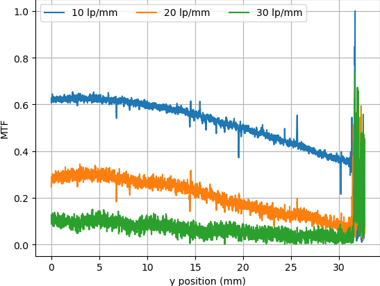
The first post attempts to quantify the optical capabilities of the scanner by determining its modulation transfer function (MTF), point spread function (PSF), and comparing its horizontal and vertical resolution. As you might expect, the nuances of these measurements are a bit beyond the average user. The short version of his analysis is that the scanner’s slide frame does indeed seem to be holding objects at the proper “sweet spot” for this particular image sensor; meaning that contrary to the advice he’d seen online, there’s nothing to be gained by purchasing custom film or slide holders.
MTF versus height of film from bed.
While investigating the optical properties of the scanner, [Andrew] became curious about the automatic focus options offered by the VueScan software he was using. The images produced appeared to be identical regardless of what option he selected, and he began to suspect the feature wasn’t actually doing anything. To confirm his theory, he wrote a shim program that would sit between the proprietary VueScan program and the V550 driver and log all of the data passing between them.
After tweaking various options and comparing the captured data streams, [Andrew] determined that enabling automatic focus in VueScan doesn’t do anything. At least, not with his scanner. He did notice a few extra bytes getting sent to the driver depending on which focus options were selected, but the response from the scanner didn’t change. He thinks the program likely has some kind of generic framework for enabling these kind of features on supported hardware, and it’s just mistakenly showing the autofocus options for a scanner that doesn’t support it.
From his comments about the noisy image and limited controls, we’re going to go out on a limb and assume [Andrew Jeddeloh] isn’t a huge fan of using his Epson V550 for scanning film. But is it really irredeemable? That’s what he set out to determine in a recent series of posts on his blog, and from what we can tell, it’s not looking good for the old Epson.
The first post attempts to quantify the optical capabilities of the scanner by determining its modulation transfer function (MTF), point spread function (PSF), and comparing its horizontal and vertical resolution. As you might expect, the nuances of these measurements are a bit beyond the average user. The short version of his analysis is that the scanner’s slide frame does indeed seem to be holding objects at the proper “sweet spot” for this particular image sensor; meaning that contrary to the advice he’d seen online, there’s nothing to be gained by purchasing custom film or slide holders.
MTF versus height of film from bed.
While investigating the optical properties of the scanner, [Andrew] became curious about the automatic focus options offered by the VueScan software he was using. The images produced appeared to be identical regardless of what option he selected, and he began to suspect the feature wasn’t actually doing anything. To confirm his theory, he wrote a shim program that would sit between the proprietary VueScan program and the V550 driver and log all of the data passing between them.
After tweaking various options and comparing the captured data streams, [Andrew] determined that enabling automatic focus in VueScan doesn’t do anything. At least, not with his scanner. He did notice a few extra bytes getting sent to the driver depending on which focus options were selected, but the response from the scanner didn’t change. He thinks the program likely has some kind of generic framework for enabling these kind of features on supported hardware, and it’s just mistakenly showing the autofocus options for a scanner that doesn’t support it.
Linker scripts are one of those things which nobody who does software development really wants to deal with, but like many things in life sometimes they are inevitable to make things work. Although one could keep pretending linker scripts do not exist and let IDEs handle such pesky details, some of us suffer from this unfortunate condition called ‘curiosity’ and just have to know. People like [Thea].
Recently, [Thea] wrote a blog post on exactly what the linker script generated by the Microchip IDE for a Cortex-M-based SAM D21 project does. The result is a nicely annotated overview of the file’s contents, accompanied by links to the Arm and GCC documentation as well as other references where appropriate. The entire linker script (.ld file) can be viewed on GitHub. With the SAM D21 being a popular choice for Arduino and Arduino-compatible board, this article is a good starting point to understanding what a linker script does and how it affects one’s project.
For other (Cortex-M) MCUs this linker script is also useful as a starting point. Especially knowing which sections are required and what changing them affects in the final (ELF) binary and the firmware that is ultimately written to the MCU. We recently covered linker scripts for Cortex-M as well, along with the concept of memory-mapped I/O.
[Chuck] likes the ability of Simplify3D to add support to parts of a model manually. However, not everyone wants to spend $150 for a slicer, so he’s shared how to install a plugin that allows you to do the same trick in Cura.
The plugin is “Cylindric Custom Support.” That doesn’t sound very exciting, but you get five choices of shapes you can create custom supports easily. There are also size and angle parameters you can use to customize the effect.
The cylinder and cube choices are pretty obvious, but the explanation of abutment support is useful. [Chuck] shows how this can be more efficient than the default support.
Of course, the proof is in the print, and the model looked pretty good for a first attempt. [Chuck] mentions that he should have made larger supports, which is possible, of course.
We liked his earlier video on tree supports, which also talks about support in general, so if you aren’t doing much with support in Cura, you might check that one out, too. It explains a lot of the support options you can tune.
We used to think we really wanted water-soluble support, but modern slicers do a good job of making support material easy to remove. You can also try providing a release agent. If you want some more background on support, here you go.
For map-lovers like [Christopher Getschmann], poring over a quality map can be as satisfying as reading a good book. Good maps can be hard to come by, though, especially at a scale worth looking at, or worth using as adornment on a dull, lifeless wall. The solution is obvious: build a wall-mount CNC plotter to draw maps directly on the wall.
[Christopher] began his map quest by scraping world map data from a number of sources, including OpenStreetMap, Natural Earth, and GEBCO. This gave him data for coastlines, terrain, and bathymetry — enough for a map of the world large enough to fill a wall. Since the scale of the map would preclude the use of even a large-format inkjet printer, [Christopher] set about building a wall-covering pen-plotter to render the map. The CoreXY-style plotter is large, but still light enough to hang on the wall while it works, and to be repositioned to cover a larger area.
The plotter runs on steppers driven by ultra-quiet Trinamic TMC5160 drivers, so the plotter wouldn’t be a nuisance while it worked. The map was plotted on eight pieces of cardboard mounted directly to the wall, filling the 2- x 3-meter space almost entirely. Landmasses and elevation contours were plotted as continuous lines in black ink, while bathymetric data was rendered in blue ink as cross-hatching with variable spacing, to make deeper oceans darker blue.
We find [Christopher]’s map breathtaking, all the more so considering the work that went into making it. It would be interesting to find alternate uses for the plotter, which reminds us a little of a cross between a draw-bot and a Maslow vertical CNC router, now that it’s done with its cartographic duties.
You may not have noticed, but we here at Hackaday really love our clicky stuff. Clicky mechanical keyboards, unnecessarily noisy flip-dot displays, and pretty much anything made with a lot of relays — they all grab our attention, in more ways than one. So it’s with no small surprise that we appear to have entirely missed perhaps the clickiest build of all: a fully operational 8-bit computer using nothing but relays.
What’s even more amazing about our failure to find and feature [Paul Law]’s excellent work is that he has been at it for the better part of a decade now. The first post on his very detailed and very well-crafted blog describing the build dates from 2013, when he was just testing LEDs in the arithmetic-logic unit (ALU). Since then, [Paul] has made incredible progress, building module after module, each containing a small portion of the computer’s functionality. The modules plug into card cages with backplanes to connect them, and the whole thing lives in an enclosure made from aluminum extrusion and glossy black panels for a truly sleek look. The computer is incredibly compact for something that uses 400+ DPDT relays to do its thinking.
In addition to the blog, [Paul] has a criminally undersubscribed YouTube channel with a quite recent series going over the computer in depth. We included the overall tour below, but you should really check out the rest of the videos to appreciate how much work went into this build. We’ve seen relay computers ranging in size from single-board to just plain ludicrous, but this one really takes the prize for fit and finish as well as functionality.