This began by collecting 150 pounds (!) of magnetic dirt from dry lake beds while hiking using a magnet pickup tool with release lever that he got from Harbor Freight. Several repeated magnetic refining passes separated the black ore from non-metallic sands ready for the furnace that he built by [IllyriaD]. That is used to fire up the raw materials using 150 pounds of charcoal, changing the chemical composition by adding carbon and resulting in a gnarly lump of iron known as a bloom.
From there it’s just a matter of beating the iron bloom into submission over at the anvil. [IllyriaD] Details the process of flattening it out to a bar shape, then folding it over. Seven total folds are made for 128 layers, and in the gallery there’s a fantastic image that captures the striation when viewed on end. After being sharpened and polished, you can see where the bevel descends through those layers.
It’s delightful to see people working through the old ways and proving you don’t need a factory, as long as your true goal is to explore the process itself. Does this leave you wanting even more? [IllyriaD] left some insight about the process in the comments of the reddit thread. You probably also want to check out the tile-roofed hut built by [PrimitiveTechnology] without any modern tools.
The Stargate Universe franchise has spawned numerous movies, serials, books, comics and games since 1994, and has been a favorite among science fiction fans. Prop makers and hackers often try building their own Stargate replica – the Einstein–Rosen bridge portal that allows almost instantaneous travel between two distant locations. Building an authentic looking prop requires a lot of attention to detail, and [Kristian]’s The Stargate Project is an amazingly well built rendition of the portal.
[Kristian]’s Stargate is mostly 3D printed and features a symbol ring, with chevrons that lock and light up when engaged. When the correct address has been dialled in, the wormhole is established, via an infinity mirror effect that uses 122 RGB LEDs. The Dial Home Device (DHD) is a replica of the original pedestal shaped computer, with two concentric sets of 19 buttons and a central activation button.
The Stargate ring is assembled from multiple 3D printed in sections, and measures 390 mm across. The seven Chevrons move along 3D printed rack-and-pinion gears, driven by geared micro-motors. The symbol ring is driven by a separate NEMA14 stepper motor. A Raspberry Pi with three piggy backed motor hats controls the various motors and LEDs. A USB sound card and a powered speaker provide audio effects while dialling. Once a worm hole is established, random audio snippets are played. The wormhole is maintained for 38 minutes, after which the Stargate powers down.
The Dial Home Device is built around a custom, circular PCB which holds the keypad buttons, LEDs and an ATmega 32u4 micro-controller which connects to the Raspberry Pi via USB. The 39 LEDs are APA102C’s so they only need two GPIO pins. For the keyboard, four banks of nine buttons and another bank of three are connected via a resistive ladder to the analog GPIO’s. This allows all 39 buttons to be connected via five analog inputs and was probably done to simplify PCB track layout. The back lit button key caps were printed in two parts. The translucent bases are covered with the opaque symbol caps.
Making a prop like this look like the real deal requires a lot of effort in painting the various parts, and this shows in [Kristian]’s final result, right down to the stone platform on which the Stargate sits. The one improvement we would like to see is a wireless DHD, just like it’s supposed to be. Doing so shouldn’t be too difficult, and losing the USB tether between the Stargate and its DHD would be a great upgrade to this amazing project. Check out the videos after the break, and there are many more on [Kristian]’s project page.
The Stargate Universe franchise has spawned numerous movies, serials, books, comics and games since 1994, and has been a favorite among science fiction fans. Prop makers and hackers often try building their own Stargate replica – the Einstein–Rosen bridge portal that allows almost instantaneous travel between two distant locations. Building an authentic looking prop requires a lot of attention to detail, and [Kristian]’s The Stargate Project is an amazingly well built rendition of the portal.
[Kristian]’s Stargate is mostly 3D printed and features a symbol ring, with chevrons that lock and light up when engaged. When the correct address has been dialled in, the wormhole is established, via an infinity mirror effect that uses 122 RGB LEDs. The Dial Home Device (DHD) is a replica of the original pedestal shaped computer, with two concentric sets of 19 buttons and a central activation button.
The Stargate ring is assembled from multiple 3D printed in sections, and measures 390 mm across. The seven Chevrons move along 3D printed rack-and-pinion gears, driven by geared micro-motors. The symbol ring is driven by a separate NEMA14 stepper motor. A Raspberry Pi with three piggy backed motor hats controls the various motors and LEDs. A USB sound card and a powered speaker provide audio effects while dialling. Once a worm hole is established, random audio snippets are played. The wormhole is maintained for 38 minutes, after which the Stargate powers down.
The Dial Home Device is built around a custom, circular PCB which holds the keypad buttons, LEDs and an ATmega 32u4 micro-controller which connects to the Raspberry Pi via USB. The 39 LEDs are APA102C’s so they only need two GPIO pins. For the keyboard, four banks of nine buttons and another bank of three are connected via a resistive ladder to the analog GPIO’s. This allows all 39 buttons to be connected via five analog inputs and was probably done to simplify PCB track layout. The back lit button key caps were printed in two parts. The translucent bases are covered with the opaque symbol caps.
Making a prop like this look like the real deal requires a lot of effort in painting the various parts, and this shows in [Kristian]’s final result, right down to the stone platform on which the Stargate sits. The one improvement we would like to see is a wireless DHD, just like it’s supposed to be. Doing so shouldn’t be too difficult, and losing the USB tether between the Stargate and its DHD would be a great upgrade to this amazing project. Check out the videos after the break, and there are many more on [Kristian]’s project page.
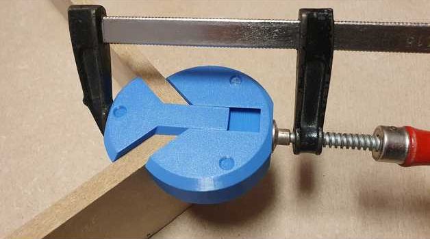
We love this design’s simplicity, but its mundane appearance is deceptive because a lot is going on here. [Bas van Hassel]’s clamp looks like a bench cookie or maybe a compressed hockey puck, but one pie piece-shaped quadrant extends on dovetails to form a right-angle channel, perfect for holding your ninety-degree joint while your glue dries. Opposing disc edges are flat, so your clamp won’t slip. Divots on the top and bumps on the bottom keep your stacks nice and neat when you put them away. All around, we have no trouble believing this designer has spent a lot of hours in the woodshop.
As long as your wood pieces are the same thickness, it seems like a practical use of printer filament, but if you have different sizes, you can always pull the dovetail out of its groove. Thanks to the scaling feature built into slicing programs, we expect some precision makers to utilize this in projects like dollhouses and model airplanes. If you have a high-resolution printer, you could make some miniature tools to construct a flea circus set. At that point, you may need to make some smaller clamps.
Print orientation for the puck is straightforward as it is a print-in-place design, but sometimes it isn’t always clear, so listen to those who know better and don’t be afraid of gears in your vises.
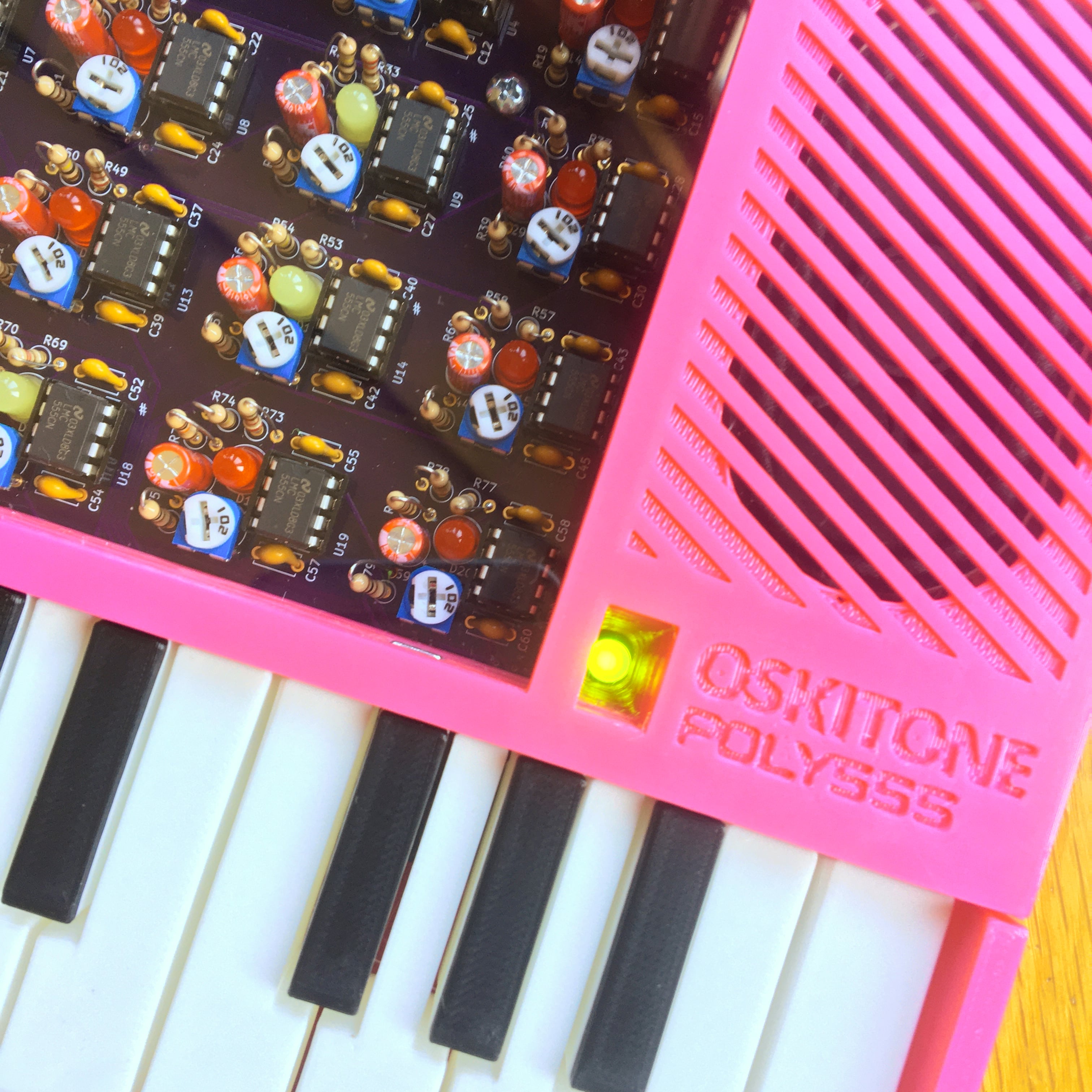
[Tommy]’s POLY555 is an analog, 20-note polyphonic synthesizer that makes heavy use of 3D printing and shows off some clever design. The POLY555, as well as [Tommy]’s earlier synth designs, are based around the 555 timer. But one 555 is one oscillator, which means only one note can be played at a time. To make the POLY555 polyphonic, [Tommy] took things to their logical extreme and simply added multiple 555s, expanding the capabilities while keeping the classic 555 synth heritage.
The real gem here is [Tommy]’s writeup. In it, he explains the various design choices and improvements that went into the POLY555, not just as an instrument, but as a kit intended to be produced and easy to assemble. Good DFM (Design For Manufacturability) takes time and effort, but pays off big time even for things made in relatively small quantities. Anything that reduces complexity, eliminates steps, or improves reliability is a change worth investigating.
For example, the volume wheel is not a thumbwheel pot. It is actually a 3D-printed piece attached to the same potentiometer that the 555s use for tuning; meaning one less part to keep track of in the bill of materials. It’s all a gold mine of tips for anyone looking at making more than just a handful of something, and a peek into the hard work that goes into designing something to be produced. [Tommy] even has a short section dedicated to abandoned or rejected ideas that didn’t make the cut, which is educational in itself. Want more? Good news! This isn’t the first time we’ve been delighted with [Tommy]’s prototyping and design discussions.
POLY555’s design files (OpenSCAD for enclosure and parts, and KiCad for schematic and PCB) as well as assembly guide are all available on GitHub, and STL files can be found on Thingiverse. [Tommy] sells partial and complete kits as well, so there’s something for everyone’s comfort level. Watch the POLY555 in action in the video, embedded below.
[Tommy]’s POLY555 is an analog, 20-note polyphonic synthesizer that makes heavy use of 3D printing and shows off some clever design. The POLY555, as well as [Tommy]’s earlier synth designs, are based around the 555 timer. But one 555 is one oscillator, which means only one note can be played at a time. To make the POLY555 polyphonic, [Tommy] took things to their logical extreme and simply added multiple 555s, expanding the capabilities while keeping the classic 555 synth heritage.
The real gem here is [Tommy]’s writeup. In it, he explains the various design choices and improvements that went into the POLY555, not just as an instrument, but as a kit intended to be produced and easy to assemble. Good DFM (Design For Manufacturability) takes time and effort, but pays off big time even for things made in relatively small quantities. Anything that reduces complexity, eliminates steps, or improves reliability is a change worth investigating.
For example, the volume wheel is not a thumbwheel pot. It is actually a 3D-printed piece attached to the same potentiometer that the 555s use for tuning; meaning one less part to keep track of in the bill of materials. It’s all a gold mine of tips for anyone looking at making more than just a handful of something, and a peek into the hard work that goes into designing something to be produced. [Tommy] even has a short section dedicated to abandoned or rejected ideas that didn’t make the cut, which is educational in itself. Want more? Good news! This isn’t the first time we’ve been delighted with [Tommy]’s prototyping and design discussions.
POLY555’s design files (OpenSCAD for enclosure and parts, and KiCad for schematic and PCB) as well as assembly guide are all available on GitHub, and STL files can be found on Thingiverse. [Tommy] sells partial and complete kits as well, so there’s something for everyone’s comfort level. Watch the POLY555 in action in the video, embedded below.
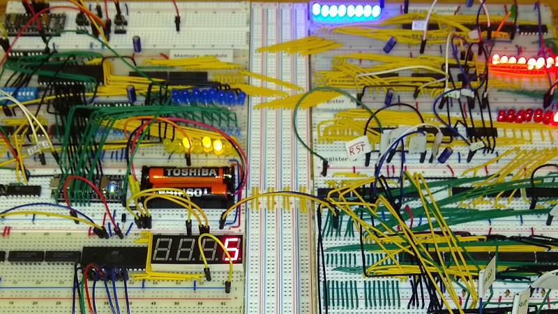
Making a CPU or indeed a whole computer system from scratch using discrete logic chips is by no means an unusual project, but it’s still one that requires quite a lot of technical ability and understanding of how computers work. Similarly, writing a UNIX-like operating system from scratch is something that’s been done more than once, but which definitely puts the author in an exclusive breed. Creating a CPU and computer system from discrete logic and then writing a UNIX-like OS for it? That’s definitely something new, but here’s [RobotMan2412] with both CPU and operating system to prove it!
The GR8CPU as he calls it is an 8-bit design with a 16-bit address space, making it equivalent to a typical mid-to-late 1970s 8-bit chip. He’s on revision 3 of the processor, and even makes the bold suggestion that it might be the most complex breadboard CPU ever made. That’s impressive enough, but to add a UNIX-like operating system makes it special.
While he has a real GR8CPU, it appears he’s also written an emulator with access to a disk filesystem, and it’s on this that he shows us the OS running. Don’t expect an all-singing all-dancing desktop OS here, instead it’s a kernel and very basic command line that’s just about able to run a Hello World. The kernel is hand-coded in assembler and is about 5 kB in size.
We look forward to seeing more of this project, and hope maybe he’ll one day soon publish the source. As a reminder that this is a perfectly capable platform for the job, here’s the original UNIX running on a vintage DEC PDP7.
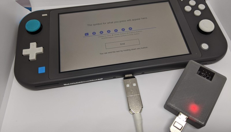
[Facelesstech] programmed an Arduino Pro Micro to fake controller button presses. It starts with a couple of presses to identify itself to the Switch, before generating an endless stream of button presses that automatically catch every shooting star. Hooking it up is easy—an on-the-go adapter allows the Switch’s USB-C port to connect directly to the Arduino’s Micro-USB port, even supplying power!
[Facelesstech] also designed a compact 3D-printed case that packages up the Arduino Pro Micro along with an ISP header for easy updating. The case even lets the Arduino’s power LED shine through so you know that it’s working!
If you, too, need to automate video game button-pushing, [Facelesstech] has kindly uploaded the source code and 3D designs for you to try. If you’d prefer something a little more low-tech, perhaps you might try a mechanical button pusher.
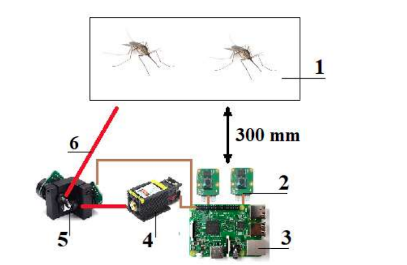
When we first heard of [Ildar Rakhmatulin’s] plan to use OpenCV on a Raspberry Pi to detect mosquitos and then zap them with a 1 watt laser, we thought it was sort of humorous. However, the paper points out that 700,000 people die each year from mosquito bites — we didn’t verify that, but according to the article that’s twice the number of people murdered each year. So the little pests are pretty effective assassins.
It looks as though the machine has been built, at least in a test configuration. A galvanometer aims the death ray using mirrors, and with the low power and lossy mirrors the mosquitos can only be a small distance from the machine — about a foot.
Even so, the paper claims they could neutralize two mosquitos per second. We wonder how many of them survived but were blinded. There were several different detection algorithms in Python but even the best algorithms didn’t track 100% and the actual kill rate of mosquitos was quite low, topping out at 15%.
Clearly, this has some work to do, but if you decide to tackle it, the research will be invaluable. There was talk of using a different camera lens to get a larger volume of detection and, of course, a more powerful laser. If the tracking algorithm could be pushed to a smaller controller, the system could be light enough and power efficient enough to fly on a drone. However, we were unclear how you’d protect non-mosquitos from being hit with the laser of death. While a 1-watt laser might not kill you, even a 1 mW laser can produce effects on your eye greater than staring into the bright sun.
We know you’re beautiful, but maybe that cheap web camera from 2007 doesn’t always project your best image. Although web cameras are starting to come back down from the pandemic price gouging days, you could just build yourself a ring light and go from there, because better light may be all you need to look great.
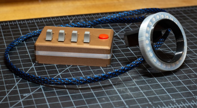
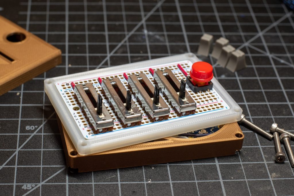
Of course, this isn’t going to be cheaper than just buying a ring light, but if you already have a Circuit Playground and 3D printer lying around, you’re about halfway to owning one that’s much cooler than anything you can buy. The only other major hardware is the RGBW LED ring, the slide pots that adjust the light color, and the clicky little button that exits out of Zoom calls.
The business part is made to mount right over the camera, so the only part that has a footprint is the control box. No need to make space for a tripod or another boom. If you’re worried about staring into a bunch of lights, there’s a diffusing ring among the print files. We think this setup looks great, especially since [Southern Fried Science] built a light guide into the enclosure so those LED on the Circuit Playground don’t go to waste.
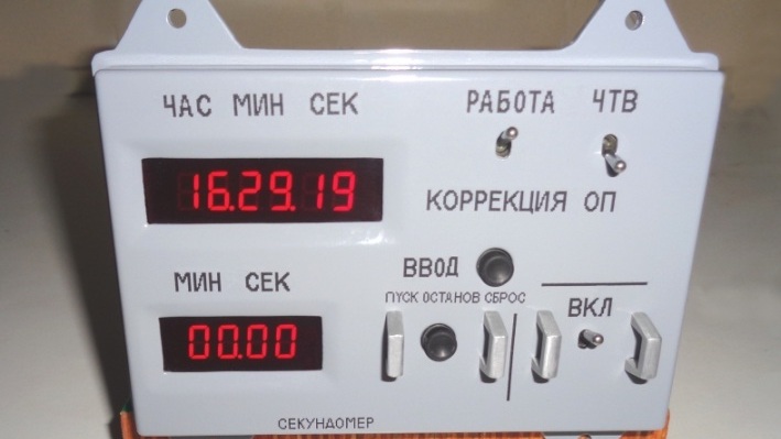
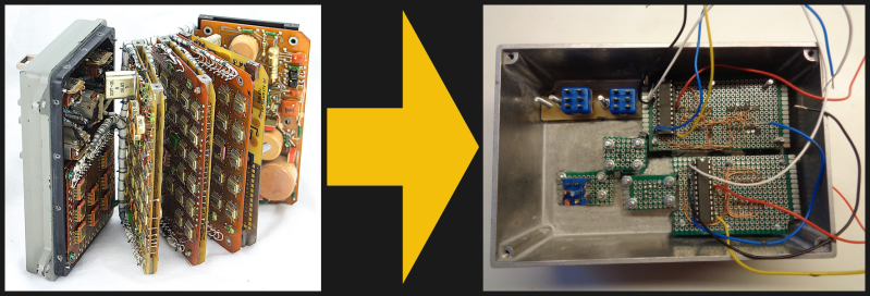
If you like the retro look of old Soviet space hardware, then this replica of the model 774H Soyuz digital clock by [David Whitty] might be the perfect accessory for your desk. Forgoing the original stack of ten jam-packed circuit boards, [David] used an Arduino, a GPS receiver, and a handful of other common parts to create a convincing reproduction.
Out with the old, in with the new
He also made some functional changes to make it better suited as an ordinary clock for us earthbound folk. If you want to take on this project yourself, be prepared for some real metalwork. No 3D printing filament was harmed in building this project. It’s based on a pair of heavily modified Hammond cast aluminum enclosures, with over 1 kg of lead ballast added to give it the appropriate heft of the original. The GPS patch antenna is cleverly hidden on the rear interface connector, but a discrete hole for a USB connector gives away the secret that this isn’t an original. The software (free for non-commercial use) and build notes are available on his GitHub repository.
We covered [Ken Shirriff]’s fascinating dive into the guts of a real Soyuz digital clock back in January. If old space hardware is your thing, you should definitely check out this teardown by [CuriousMarc] of the 653B, the 1960s-era electro-mechanical predecessor to the 774H. Thanks to [CuriousMarc] for bringing this project to our attention.
If you like the retro look of old Soviet space hardware, then this replica of the model 774H Soyuz digital clock by [David Whitty] might be the perfect accessory for your desk. Forgoing the original stack of ten jam-packed circuit boards, [David] used with an Arduino, a GPS receiver, and a handful of other common parts to create a convincing reproduction.
Out with the old, in with the new
He also made some functional changes to make it better suited as an ordinary clock for us earthbound folk. If you want to take on this project yourself, be prepared for some real metalwork. No 3D printing filament was harmed in building this project. It’s based on a pair of heavily modified Hammond cast aluminum enclosures, with over 1 kg of lead ballast added to give it the appropriate heft of the original. The GPS patch antenna is cleverly hidden on the rear interface connector, but a discrete hole for a USB connector gives away the secret that this isn’t an original. The software (free for non-commercial use) and build notes are available on his GitHub repository.
We covered [Ken Shirriff]’s fascinating dive into the guts of a real Soyuz digital clock back in January. If old space hardware is your thing, you should definitely check out this teardown by [CuriousMarc] of the 653B, the 1960s-era electro-mechanical predecessor to the 774H. Thanks to [CuriousMarc] for bringing this project to our attention.
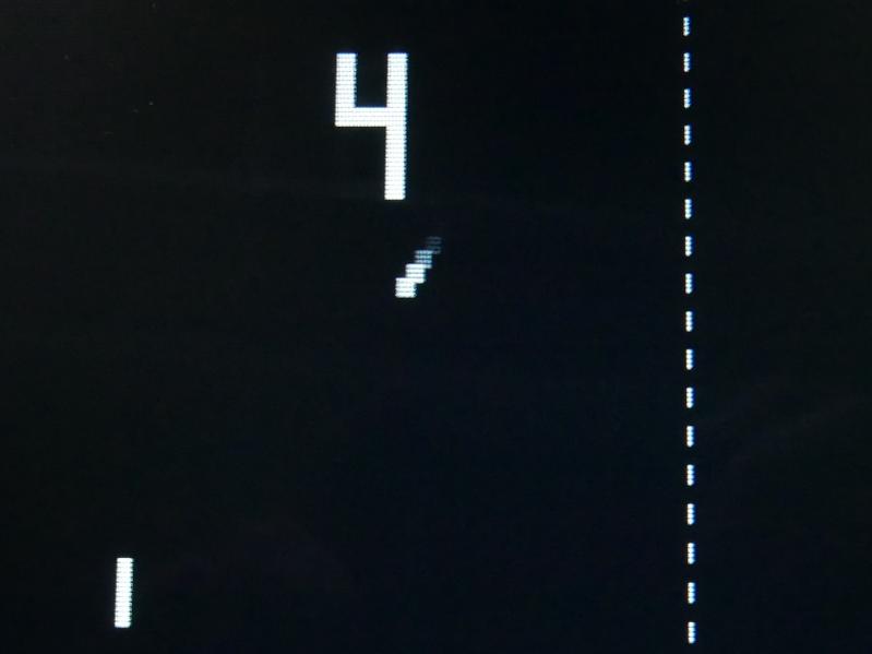
Instead of trying to cram a CRT in that nice mahogany cabinet, [Jürgen] opted to use an 8″ TFT screen. But get this: [Jürgen] built a Spartan 6 FPGA-based upscaler to adds the scan lines, blur, and afterglow that make it look like the classic PONG experience.
[Jürgen] also built an interface board that amplifies the sound, splits the video out into sync and brightness for the upscaler, and provides 5 V to the PONG circuit board. [Jürgen] decided to circumvent the board’s native voltage regulator in the name of keeping things cool.
[Jürgen] says the project’s web page is in a preliminary stage right now with more information to come. We sure hope that includes a video of it in action. For now, you can check out the files for the interface PCB, the FPGA board, and a list of the fonts.
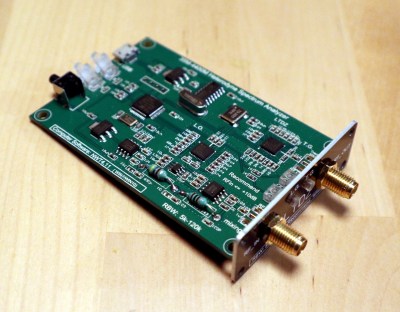
As mildly exotic silicon has become cheaper and the ingenuity of hardware hackers has been unleashed upon it, it’s inevitable that some once-unattainably expensive instruments will appear as cheap modules from China. The LTDZ spectrum analyser on the bench today covers 35 MHz to 4.4 GHz, and has a USB interface and tracking source. It has been available from all the usual outlets for a while now either as a bare PCB or in a metal box about the size of a pack of cards.
We’ve already taken a look at the $50 VNA, and this time it’s the turn of the $30 spectrum analyser, in the form of a little device that I succumbed to while browsing Banggood.
I ordered one, along with an attenuator and RF bridge for SWR measurements, and after the usual wait for postage my anonymous grey package arrived and it was time to give it a look and consider its usefulness. It’s a design derived from one published in Germany’s Funkamateur (“amateur radio”) magazine early in the last decade, and unscrewing the end plate to slide out the board from its extruded enclosure we can see what makes it tick.
How Much RF Test Equipment Hardware Does $30 Get you?
Its operation is surprisingly simple, in effect a very wideband radio receiver and signal source that can sequentially check signal levels across its range under the control of a microcomputer. On the board is an STM32F103 microcontroller that drives a pair of ADF4351 PLL frequency synthesisers for tracking and receive local oscillator respectively, an IAM-81008 receive mixer, and an AD8307 logarithmic amplifier to measure the received level. It’s reported as having a receive bandwidth in the region of 150 kHz, but I lack the instrumentation to measure that. On the rear edge of the board is a micro-USB socket, a couple of LEDs, and a “Key” switch to enable the tracking oscillator, and on the front are a pair of SMA sockets for RF input and output.
This product has caused [DL4JAL] something of a headache, we’d like to ask you don’t add to that if you use it.
Hardware-wise all seems in order, but it’s a different tale on the software side. The history is related by [VMA’s Satellite Blog], and is a salutary tale of how cheaply cloned hardware can have unfortunate consequences. The WinNWT and LinNWT software used by the original Funkamateur design came from [Andreas Lindenau, DL4JAL], and was available from his website. The Funkamateur design was improved upon by other radio amateurs around the world, including a Chinese amateur [BG7TBL] who produced the design I have on my bench. When this was taken up by manufacturers and sold in volume, [DL4JAL] found himself fielding unsustainable levels of support queries. He thus withdrew the original NWT4 software from his website.
If you buy one of these you will almost certainly be offered a download from the vendor. In my case I couldn’t find a Linux version, and tried the NWT4000 software which worked with my spectrum analyser despite claims to the contrary. To respect his wishes we’ll not put a link to his website here, but if you use his software of whatever version on one of these units we would like to request that you do not trouble him for support. Happily the [DL4JAL] software isn’t the only game in town, with both VMA Simple Spectrum Analyser and SNA Sharp being readily available alternatives. They are however both Windows-only, and the former requires a paid activation key for long-term use.
When You Have A Spectrum Analyser, Everything Is An RF Source
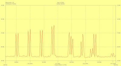
The not-very-crowded FM broadcast spectrum of rural Central England.
Once I had my device plugged in and detected by the software, it was time to calibrate it. This process simply generates a record of the device’s performance while directly reading its tracking generator, allowing the software to create a flat baseline. Calibration involves running a scan first with tracking source connected to the input through an attenuator, then directly. Once this has been done it is then possible to read a flat line across the frequency range without any test devices connected. To my shame, it took me a while to realise that pressing the “Key” button was necessary to enable the tracking generator.
So, I have a spectrum analyser here on my bench, what next? Of course the first thing was to plug in an antenna and take a look at the off-air spectrum. I could home in on the FM band and see all the local stations that you’d find in a small British town, and I could see the TV multiplex transmissions, the home WiFi, and my mobile phone when I made a call. Having a new toy sends you scurrying around the house in search of radio sources, so I can confirm that variously a UHF remote, a DECT handset, and my Baofeng handheld radio all produce satisfying spikes on the graph.
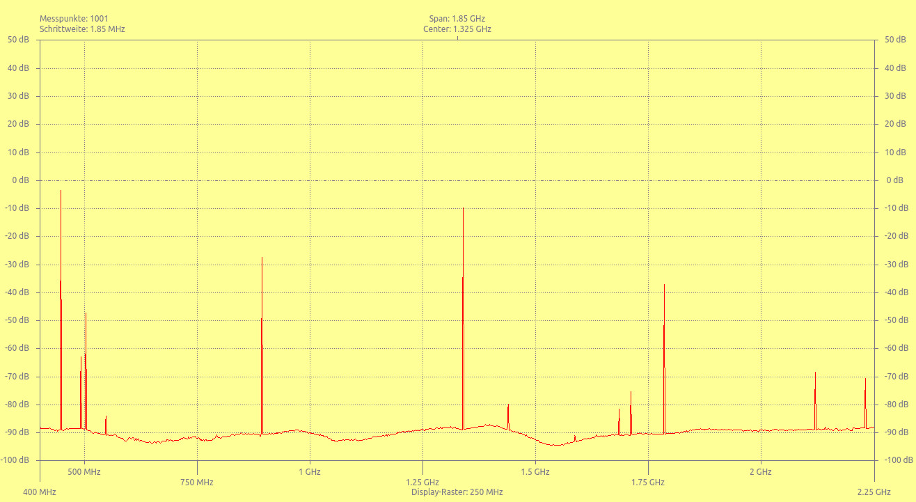
Only one of these spikes is supposed to be there in any quantity.
It’s all very well to have a spectrum analyser to look at the pretty spikes, but it’s time to do something useful. The most obvious thing to try would be to characterise an antenna using the RF bridge, but sadly with most of my radio stuff in storage I don’t have a suitably narrow-band antenna to measure.
Instead I can check the spectral purity of my Baofeng transceiver, and for that all I need is the attenuator. The procedure is simple enough, connect the Baofeng’s antenna output through the attenuator to the spectrum analyser input, and take a spectrum reading. My back-of-the-envelope reckoning tells me that with the transmit power on the 100 mW “low” setting, the 20dB attenuator should be enough to reduce the level so as not to harm the analyser, and its input resistor should be capable of taking 100 mW for a short time. Setting it up in this way and pressing the transmit button, I could instantly see why there is some concern about the filtering on these cheaper radios. It has quite a few spurious spikes in the space between the 435 MHz fundamental and the first harmonic, then particularly strong subsequent harmonics. You get what you pay for in a transmitter.
So for $30, I seem to have picked up a useful little instrument that’s more than a toy and that can do some useful RF tasks on my bench. The $30 price tag makes itself felt though in that it has nowhere near the sensitivity and selectivity of its more expensive brethren, and its 35 MHz lower limit is too high for investigating noise emissions. Meanwhile the software has some availability issues over which we sympathise with its author, and we can’t help wishing that it had an open-source option available. For $30, it was worth it, but for much more I’d have to ask myself whether I would think the same. Perhaps for the lower frequencies in particular, a TinySA might be a better purchase.
Every summer you go down the shore, but lately you’ve begun to notice that the beach seems narrower each time you visit. Is that the sea level rising, or is the sand just being swept away? Speaking of sea levels, you keep hearing that they rise higher every year — but how exactly is that measured? After all, you can’t exactly use a ruler. As it turns out, there are a number of clever systems in place that can accurately measure the global sea level down to less than an inch and a half.
Not only are waves always rippling across the ocean’s surface, but tides periodically roll in and out, making any single instantaneous measurement of sea level hopelessly inaccurate. Even if you plan to take hundreds or thousands of measurements over the course of weeks or months, taking the individual measurements is still difficult. Pick a nice, stable rock in the surf, mark a line on it, and return every hour for two weeks to hold a tape measure up to it. At best you’ll get within six inches on each reading, no matter what you’ll get wet, and at worst the rock will move and you’ll get a damp notebook full of useless numbers. So let’s take a look at how the pros do it.
Expensive Rulers
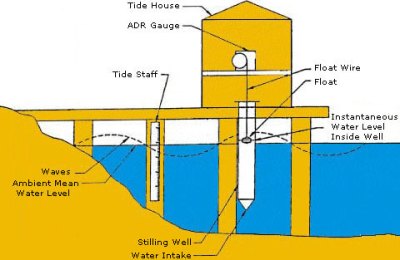
As it turns out, measuring sea level with a ruler isn’t that far off — but professional oceanographers have really nice ones called tide gauges, which live in aptly-named tide houses. The simplest tide gauge is a long tube sitting in the water, anchored in place. The tube has small openings below the water level that allow water to flow in and out. Also referred to as a stilling well, this device averages out small movements and waves, allowing for a much more calm and accurate measurement against a series of graduations inside the tube.
Of course, manually making all these measurements is tedious work, and today there are computerized methods for recording tide levels. Even so, some tide houses had automated recording systems as early as 1830. These systems consisted of a float in the stilling well, which moved a “pen” by way of rope and pulley. Every six minutes, the pen would mark the tide level on paper, much in the way an old seismometer works.
Over the years, the stilling well has evolved into the sounding tube — rather than a float on a rope, the sounding tube sends an audio pulse down the tube and measures the time it takes for the pulse to bounce off the water surface and return to a sensor. Recently, NOAA has developed a new system that uses microwave radar to measure the water level. Microwave sensors don’t need a stilling well- they can be mounted to a structure that sits above the water. This is a massive advantage, because servicing the sensor is much easier if you don’t need to don a wetsuit and air tank. In the coming years, NOAA is planning to transition it’s acoustic measurement stations to this new microwave technology.
So, if you can measure sea level without ever touching the water, from how far away can you measure, exactly?
Send In The Satellites
As it turns out, you can take measurements from pretty far away — about 830 miles away, to be exact.
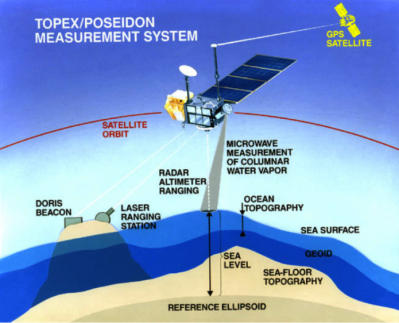
In 1992, an Ariane 4 rocket hurdled up from the Guiana Space Center to deliver the TOPEX/Poseidon satellite into orbit. The satellite carried an impressive array of instruments including two radar altimeters, a microwave radiometer, GPS receivers, and a laser retroreflector array. The GPS system was able to pinpoint the satellite’s location to within an inch, and was the first system to demonstrate that GPS satellites could be used to locate another spacecraft rather than only terrestrial targets.
The TOPEX/Poseidon system was groundbreaking for a number of reasons. Not only was it able to measure sea level to an incredible degree of accuracy (1.5 inches), but it was the first mission to map the earth’s tides. It mapped currents across the ocean, and gathered valuable data that improved our understanding of climate change, weather, and even the Earth’s gravitational field.
Although the satellite was shut down in 2006 after malfunctioning, its mission was taken over by Jason-1, which was launched in 2001 to supplement TOPEX/Poseidon’s measurements. Jason-2 followed, and in 2016 the mantle was taken up by Jason-3.
We know that these satellites do a great job of measuring the sea level, but what exactly are they measuring it against?
So Is Sea Level Zero?
Well yes… and no. It depends on your reference point. If you look on any topographical map, you’ll notice that elevations are reported in height above (or occasionally, below) sea level. Pilots often report altitudes in AMSL, or Above Mean Sea Level. Mean sea level is obtained by time-averaging the still water level (SWL) to remove cyclical effect of daily tides. SWL is simply what can be measured with a tide gauge, the water level with sea motions such as wind waves smoothed out. This works well enough for measuring the elevation of things that aren’t, well, the ocean, but we run into a problem if we try to measure the ocean in terms of itself. This is where we need other references to measure against.
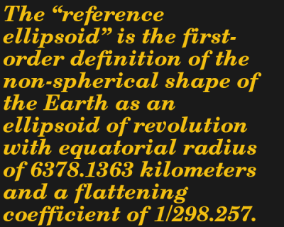
The satellite-based instruments report sea level with respect to the WGS-84 Reference Ellipsoid, defined by the TOPEX/Poseidon Data User’s Handbook as the “the first-order definition of the non-spherical shape of the Earth as an ellipsoid.” This is also the baseline GPS receivers use to convey elevation data. Another helpful reference surface is the geoid — the theoretical shape that the Earth’s ocean would make if it were free from the external influences of the Sun and other celestial bodies, only acted upon by the gravity and rotation of the Earth itself.
Does Mars Have a “Sea Level”?
This is all well and good for Earth with its vast oceans, but how is elevation measured on Mars (or other planets, for that matter) where there is no sea to reference?
If you want to measure a mountain on Mars, you better bring a barometer and a calculator. Zero elevation is defined as the isobar where the atmospheric pressure is equal to 610.5 Pa (for reference, “sea level” on earth has an atmospheric pressure of 101.5 kPa). Though seemingly selected at random, 610.5 Pa is the triple point of water on the red planet — that is, the pressure at which water can exist in its solid, liquid, and gaseous states simultaneously. From that, and a reference ellipsoid similar to the one we use for the Earth, the elevation of various geographic features is measured by laser altimeters affixed to an orbiting satellite such as the Mars Global Surveyor.
Let’s take a look at the Moon now, where the “atmospheric” pressure is effectively zero (okay, there’s some gas there but the pressure is around Pa). The Mars method won’t work here, since there’s no atmosphere to speak of. To establish the Moon’s reference ellipsoid, scientists determined its average diameter and set that as the zero. The Lunar Reconnaissance Orbiter then can measure the relative altitude of the lunar surface with respect to that datum.
Back To The Beach
So, back to our initial quandary — what exactly is causing that receding shoreline you notice year after year? On average, the global sea level rises annually by about 0.14 inches, so while global warming is a very real concern you probably aren’t noticing its effects on the shoreline one year to the next. That leaves coastal erosion — the gradual removal of sand, rocks, and soil by the ocean. It’s a good thing then, if much of the coastline is so unstable, that we have tide houses and satellites to accurately track changes in the global sea level. That rock you tried to measure against is all but guaranteed to move.
Every summer you go down the shore, but lately you’ve begun to notice that the beach seems narrower each time you visit. Is that the sea level rising, or is the sand just being swept away? Speaking of sea levels, you keep hearing that they rise higher every year — but how exactly is that measured? After all, you can’t exactly use a ruler. As it turns out, there are a number of clever systems in place that can accurately measure the global sea level down to less than an inch and a half.
Not only are waves always rippling across the ocean’s surface, but tides periodically roll in and out, making any single instantaneous measurement of sea level hopelessly inaccurate. Even if you plan to take hundreds or thousands of measurements over the course of weeks or months, taking the individual measurements is still difficult. Pick a nice, stable rock in the surf, mark a line on it, and return every hour for two weeks to hold a tape measure up to it. At best you’ll get within six inches on each reading, no matter what you’ll get wet, and at worst the rock will move and you’ll get a damp notebook full of useless numbers. So let’s take a look at how the pros do it.
Expensive Rulers
As it turns out, measuring sea level with a ruler isn’t that far off — but professional oceanographers have really nice ones called tide gauges, which live in aptly-named tide houses. The simplest tide gauge is a long tube sitting in the water, anchored in place. The tube has small openings below the water level that allow water to flow in and out. Also referred to as a stilling well, this device averages out small movements and waves, allowing for a much more calm and accurate measurement against a series of graduations inside the tube.
Of course, manually making all these measurements is tedious work, and today there are computerized methods for recording tide levels. Even so, some tide houses had automated recording systems as early as 1830. These systems consisted of a float in the stilling well, which moved a “pen” by way of rope and pulley. Every six minutes, the pen would mark the tide level on paper, much in the way an old seismometer works.
Over the years, the stilling well has evolved into the sounding tube — rather than a float on a rope, the sounding tube sends an audio pulse down the tube and measures the time it takes for the pulse to bounce off the water surface and return to a sensor. Recently, NOAA has developed a new system that uses microwave radar to measure the water level. Microwave sensors don’t need a stilling well- they can be mounted to a structure that sits above the water. This is a massive advantage, because servicing the sensor is much easier if you don’t need to don a wetsuit and air tank. In the coming years, NOAA is planning to transition it’s acoustic measurement stations to this new microwave technology.
So, if you can measure sea level without ever touching the water, from how far away can you measure, exactly?
Send In The Satellites
As it turns out, you can take measurements from pretty far away — about 830 miles away, to be exact.
In 1992, an Ariane 4 rocket hurdled up from the Guiana Space Center to deliver the TOPEX/Poseidon satellite into orbit. The satellite carried an impressive array of instruments including two radar altimeters, a microwave radiometer, GPS receivers, and a laser retroreflector array. The GPS system was able to pinpoint the satellite’s location to within an inch, and was the first system to demonstrate that GPS satellites could be used to locate another spacecraft rather than only terrestrial targets.
The TOPEX/Poseidon system was groundbreaking for a number of reasons. Not only was it able to measure sea level to an incredible degree of accuracy (1.5 inches), but it was the first mission to map the earth’s tides. It mapped currents across the ocean, and gathered valuable data that improved our understanding of climate change, weather, and even the Earth’s gravitational field.
Although the satellite was shut down in 2006 after malfunctioning, its mission was taken over by Jason-1, which was launched in 2001 to supplement TOPEX/Poseidon’s measurements. Jason-2 followed, and in 2016 the mantle was taken up by Jason-3.
We know that these satellites do a great job of measuring the sea level, but what exactly are they measuring it against?
So Is Sea Level Zero?
Well yes… and no. It depends on your reference point. If you look on any topographical map, you’ll notice that elevations are reported in height above (or occasionally, below) sea level. Pilots often report altitudes in AMSL, or Above Mean Sea Level. Mean sea level is obtained by time-averaging the still water level (SWL) to remove cyclical effect of daily tides. SWL is simply what can be measured with a tide gauge, the water level with sea motions such as wind waves smoothed out. This works well enough for measuring the elevation of things that aren’t, well, the ocean, but we run into a problem if we try to measure the ocean in terms of itself. This is where we need other references to measure against.
The satellite-based instruments report sea level with respect to the WGS-84 Reference Ellipsoid, defined by the TOPEX/Poseidon Data User’s Handbook as the “the first-order definition of the non-spherical shape of the Earth as an ellipsoid.” This is also the baseline GPS receivers use to convey elevation data. Another helpful reference surface is the geoid — the theoretical shape that the Earth’s ocean would make if it were free from the external influences of the Sun and other celestial bodies, only acted upon by the gravity and rotation of the Earth itself.
Does Mars Have a “Sea Level”?
This is all well and good for Earth with it’s vast oceans, but how is elevation measured on Mars (or other planets, for that matter) where there is no sea to reference?
If you want to measure a mountain on Mars, you better bring a barometer and a calculator. Zero elevation is defined as the isobar where the atmospheric pressure is equal to 610.5 Pa (for reference, “sea level” on earth has an atmospheric pressure of 101.5 kPa). Though seemingly selected at random, 610.5 Pa is the triple point of water on the red planet — that is, the pressure at which water can exist in its solid, liquid, and gaseous states simultaneously. From that, and a reference ellipsoid similar to the one we use for the Earth, the elevation of various geographic features is measured by laser altimeters affixed to an orbiting satellite such as the Mars Global Surveyor.
Let’s take a look at the Moon now, where the “atmospheric” pressure is effectively zero (okay, there’s some gas there but the pressure is around Pa). The Mars method won’t work here, since there’s no atmosphere to speak of. To establish the Moon’s reference ellipsoid, scientists determined its average diameter and set that as the zero. The Lunar Reconnaissance Orbiter then can measure the relative altitude of the lunar surface with respect to that datum.
Back To The Beach
So, back to our initial quandary — what exactly is causing that receding shoreline you notice year after year? On average, the global sea level rises annually by about 0.14 inches, so while global warming is a very real concern you probably aren’t noticing its effects on the shoreline one year to the next. That leaves coastal erosion — the gradual removal of sand, rocks, and soil by the ocean. It’s a good thing then, if much of the coastline is so unstable, that we have tide houses and satellites to accurately track changes in the global sea level. That rock you tried to measure against is all but guaranteed to move.
When slicing a model for 3D printing, the part is divided into a stack of flat, 2D layers. But there’s an alternative in the form of non-planar slicing, where the layers can follow 3D curves. [Rene K. Mueller] took this a step further and successfully used non-planar slicing to print 90° overhangs on a normal Cartesian FDM printer.
Non-planar layers have been around for a while, but were generally limited to creating smooth curves without layer lines. The idea of using the technique for overhangs had been floating around in [Rene]’s head for a while, and he was spurred to action after seeing the rotating tilted nozzle printer featured here on Hackaday. The idea is only to have the outer edge of each layer overhang, by making each layer slope downward toward the overhang. [Rene] programmed a conic slicer algorithm for this purpose, which splits the model into dome-shaped layers, like an onion.
He did a lot of testing and documented the results in detail. Conical slices were compared with tilted slices, which are also used for belt 3D printers. Both have some geometric limitations. Tilted slices can only print the overhang in one direction, but conical slices can do this in all directions, allowing it to create a mushroom-like shape without any support. The limitation is that it can only print inward or outward from a central point. More complex geometry must be segmented, and each sub-volume sliced separately. The slicing angle is also limited by the shape of the print head, to avoid it crashing into the print.
We think this technique has a lot of potential for widespread use, especially since it is compatible with most existing FDM printers. It is still a work in progress, but support has already been added for Slic3r and Prusa Slicer. We look forward to seeing how it develops and gets adopted.
What a time to be alive when you can find inexpensive microcontrollers that come with programmable(ish) logic that can operate independently of the system clock. [David Johnson-Davies] recently built a proof of concept using the Configurable Custom Logic (CCL) that is available in some of the newer AVR microcontroller designs. It’s a simple implementation, a set of frequency dividers that blink three LEDs with up to a 90 MHz input signal. But the simplicity is the reason to love his write-up — you can wrap your head around it right away.
There are four lookup table (LUTs) used to form the frequency divider. Think of these like a NAND or XOR gate, but you get to decide how the output truth tables will perform. The output is fed into a sequencer which can be configured as a D/JK flip-flop or a D/RS latch, plus you can specify the signal edge, and of course define the clock source. An interesting trick here is to hold the G input of both D flip-flops high by feeding them LUTs set to all ones. Note that the output of the first divider (PA3) is feeding the external input (PD2) of the second divider.
While the CCL is configured using the C code you flash to the microcontroller, it’s a hardware peripheral capable of operating independent of the chip’s system clock. The AVR128DA28 that’s used here tops out at 24 MHz (double that if you use the PLL) but [David] got reliable results from his clock divider feeding a signal as high as 90 MHz to the input pin. Of course you have the option of feeding internal clock signals to the CCL, but that wouldn’t seem nearly as interesting here. For the demo, [David] is actually toggling an IO pin which is connected to PA2 as the external input for the logic. Make sure you click through to his write-up linked above as he does an excellent job of walking through the sample code (just a couple-dozen lines to set this all up). Here’s the datasheet for this chip (PDF, page 447 for pertinent registers) and for a deeper dive the appnote on CCL (PDF).
What can we say? It’s 2021, and we could probably all use a psychotic glow worm lamp in our lives about now to lighten the mood and/or provide a new focal point for sitting and staring. Tired of dragging out that creepy little Elf on the Shelf every holiday season? [LiabilityLabs]’ Head Lamp is slightly less terrifying and far more functional. Really, the options are limitless.
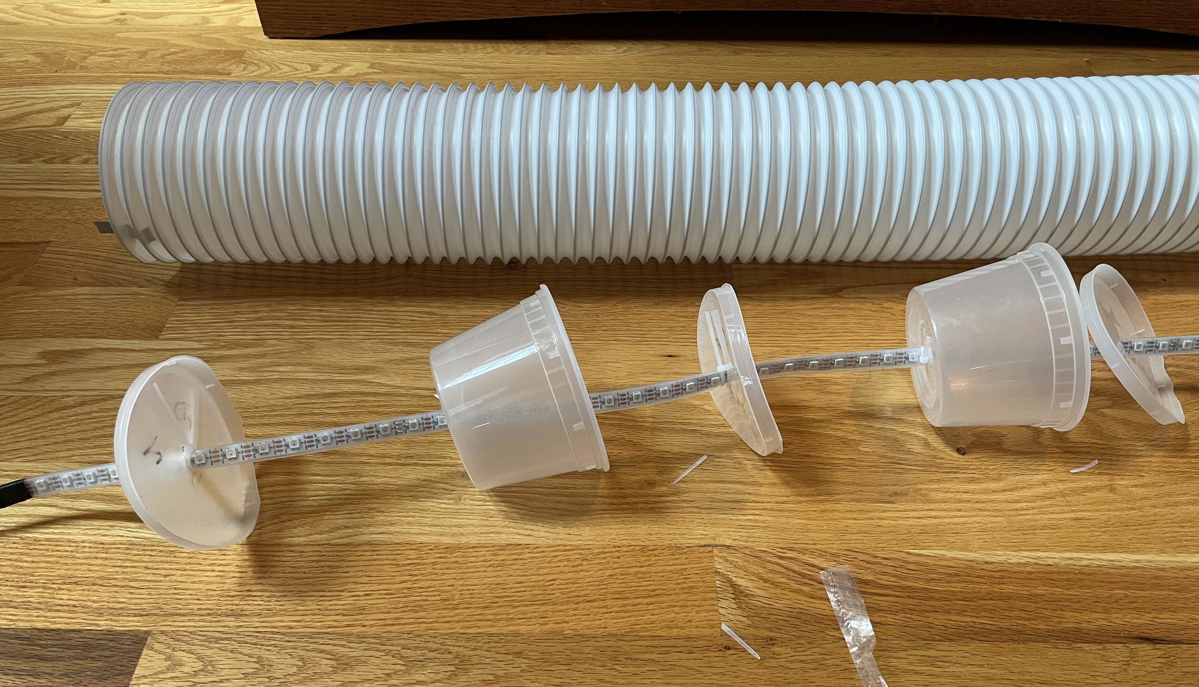
The brain of this scare snake is an Electromage Pixelblaze LED controller, a powerful Wi-Fi enabled little board with a live web editor. [LiabilityLabs] recycled 20 milky plastic containers and their lids to help diffuse the light and avoid hot spots by holding the LED strip in the center of the tube. There’s a momentary button on the glowy guy’s tail that lets [LiabilityLabs] cycle through different color patterns with ease.
Whether you need a mascot for your stream channel, a confidant, or a refreshing rainbow rubber ducky of problem solving, Head Lamp is flexible. Feast your eyes on some brief animations after the break.
What can we say? It’s 2021, and we could probably all use a psychotic glow worm lamp in our lives about now to lighten the mood and/or provide a new focal point for sitting and staring. Tired of dragging out that creepy little Elf on the Shelf every holiday season? [LiabilityLabs]’ Head Lamp is slightly less terrifying and far more functional. Really, the options are limitless.
The brain of this scare snake is an Electromage Pixelblaze LED controller, a powerful Wi-Fi enabled little board with a live web editor. [LiabilityLabs] recycled 20 milky plastic containers and their lids to help diffuse the light and avoid hot spots by holding the LED strip in the center of the tube. There’s a momentary button on the glowy guy’s tail that lets [LiabilityLabs] cycle through different color patterns with ease.
Whether you need a mascot for your stream channel, a confidant, or a refreshing rainbow rubber ducky of problem solving, Head Lamp is flexible. Feast your eyes on some brief animations after the break.
It’s March, which means Keysight is back in the business of giving away a ton of test gear. Keysight University Live starts on March 15, with daily events the first week followed by a string of weekly live events through April. We always enjoy these Keysight events; sure, they’re clearly intended to sell more gear, but the demos and tutorials are great, and we always learn a lot. There’s also a feeling of community that feels similar to the Hackaday community; just a bunch of electronics nerds getting together to learn and share. If you’re interested in that community, or even if you’re just looking for a chance to win something from the $300,000 pile of goodies, you’ll need to register.
There’s another event coming up that you’ll want to know about: the 2021 Open Hardware Summit. Because 2021 is the new 2020, the summit is being held virtually again, this year on April 9. Tickets are on sale now, and we’re told there are still plenty of Ada Lovelace Fellowships available to those who consider themselves to be a minority in tech. The Fellowship covers the full cost of a ticket; it usually covers travels costs too, but sadly we’re still not there yet.
Once we do start traveling again, you might need to plan more carefully if cities start following the lead of Petaluma, California and start banning the construction of gas stations. The city, about 40 miles (64 km) north of San Francisco, is believed to be the first city in the United States to ban new gas station construction. The city council’s decision also prevents gas station owners from expanding, reconstructing, or relocating existing gas stations. The idea is to create incentives to move toward non-fossil fuel stations, like electric vehicle charging stations and hydrogen fueling. Time will tell how well that works out.
Go home Roomba — you’re drunk. That could be what Roomba owners are saying after an update semi-bricked certain models of the robotic vacuum cleaners. Owners noted a variety of behaviors, like wandering around in circles, bumping into furniture, and inability to make its way back to base for charging. There’s even a timelapse on reddit of a Roomba flailing about pathetically in a suspiciously large and empty room. The drunken analogy only goes so far, though, since we haven’t seen any reports of a Roomba barfing up the contents of its dust bin. But we’re still holding out hope.
And finally, if you’re not exactly astronaut material but still covet a trip to space, you might luck out courtesy of Japanese billionaire Yusaku Maezawa. He’s offering to pay the way for eight people from around the world on a planned flight to the Moon and back in 2023. Apparently, Maezawa bought up all the seats for the flight back in 2018 with the intention of flying a group of artists to space. His thinking has changed, though, and now he’s opening up the chance to serve as ballast join the crew to pretty much any rando on the planet. Giving away rides on Starship might be a harder sell after this week’s test, but we’re sure he’ll find plenty of takers. And to be honest, we wish the effort well — the age of routine civilian space travel can’t come soon enough for us.
The Drive had an interesting post recently, about someone noticed a procurement from the U. S. Air Force to reverse engineer the B-2 bomber’s Load Heat Exchanger (whatever that is). You’d think if the Air Force wanted to reverse engineer something, they’d be looking at another country’s aircraft. What can this mean?
Presumably, the original plans for the system have been lost, or maybe the company who made them is long gone and the tooling to create new ones along with it. Then again, maybe the assembly needs parts that you can no longer get. The Drive has another interesting speculation: perhaps the plans were so secret that were accidentally destroyed.
You don’t hear much about the B-2. There are only 20 left of the 21 built, at least that we know about. Original plans in the 1980s called for 132, but the end of the Cold War spelled the end for the stealth bomber. They get an overhaul every nine years. The Drive also speculates that this may be part of the Air Force’s desire to digitize spare parts and use 3D printing, but — honestly — it doesn’t sound that way to us. Especially since the fleet will retire no later than 2032, so whatever is replaced is only needed for a decade.
If you think you want to have a go, here’s the help wanted ad from the Air Force. If you read the text, it’s pretty clear they have some defective units that need replacement and it sounds like no one knows how to do it with existing materials. Not many of us get to design things that are still working nearly three decades later. Keeping a supply of parts and even know-how for something built in the 1990s isn’t trivial. Something to think about if you design something with a long service life.
The B-2 is a stealth bomber and while one did crash, it wasn’t shot down. The F-117A — the stealth fighter — was shot down against all odds, though. While the B-2 appears to be quite a plane, we prefer our bombers a little bit older. Still, you might enjoy the video below about the B-2’s chief engineer, although he doesn’t mention the Load Heat Exchanger.
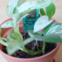
We have all been stuck inside for too long, and maybe that’s why we have recently seen a number of projects attempting to help humans take better care of their housemates from Kingdom Plantae. To survive, plants need nutrients, light, and water. That last one seems tricky to get right; not too dry and not drowning them either, so [rbaron’s] green solder-masked w-parasite wireless soil monitor turns this responsibility over to your existing home automation system.
Like this low-power soil sensor project and the custom controller for six soil sensors, [rbaron’s] w-parasite uses a “parasitic capacitive” moisture sensor to determine if it’s time to water plants. This means that unlike resistive soil moisture sensors, here the copper traces are protected from corrosion by the solder mask. For those wondering how they work, [rbaron]’s Twitter thread has a great explanation.
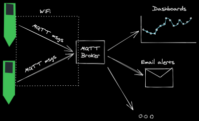
The “w” in the name is for WiFi as the built-in ESP-32 module then takes the moisture reading and sends an update wirelessly via MQTT. Depending on the IQ of your smart-home setup, you could log the data, route an alert to a cellphone, light up a smart-bulb, or even switch on an irrigation system.
[rbaron] has shared a string of wireless hacks, controlling the A/C over Slack and a BLE Fitness Tracker that inspired more soldering than jogging. We like how streamlined this solution is, with the sensor, ESP-32 module, and battery all in a compact single board design. Are you asking yourself, “but how is a power-hungry ESP-32 going to last longer than it takes for my geraniums to dry out?” [rbaron] is using deep sleep that only consumes 15uA between very quick 500ms check-ins. The rechargeable LIR2450 Li-Ion coin cell shown here can transmit a reading every half hour for 90 days. If you need something that lasts longer than that, use [rbaron]’s handy spreadsheet to choose larger batteries that last a whole year. Though, let’s hope we don’t have to spend another whole year inside with our plant friends.
We may never know why the weeds in the cracks of city streets do better than our houseplants, but hopefully, we can keep our green roommates alive (slightly longer) with a little digital nudge.
We have all been stuck inside for too long, and maybe that’s why we have recently seen a number of projects attempting to help humans take better care of their housemates from Kingdom Plantae. To survive, plants need nutrients, light, and water. That last one seems tricky to get right; not too dry and not drowning them either, so [rbaron’s] green solder-masked w-parasite wireless soil monitor turns this responsibility over to your existing home automation system.
Like this low-power soil sensor project and the custom controller for six soil sensors, [rbaron’s] w-parasite uses a “parasitic capacitive” moisture sensor to determine if it’s time to water plants. This means that unlike resistive soil moisture sensors, here the copper traces are protected from corrosion by the solder mask. For those wondering how they work, [rbaron]’s Twitter thread has a great explanation.
The “w” in the name is for WiFi as the built-in ESP-32 module then takes the moisture reading and sends an update wirelessly via MQTT. Depending on the IQ of your smart-home setup, you could log the data, route an alert to a cellphone, light up a smart-bulb, or even switch on an irrigation system.
[rbaron] has shared a string of wireless hacks, controlling the A/C over Slack and a BLE Fitness Tracker that inspired more soldering than jogging. We like how streamlined this solution is, with the sensor, ESP-32 module, and battery all in a compact single board design. Are you asking yourself, “but how is a power-hungry ESP-32 going to last longer than it takes for my geraniums to dry out?” [rbaron] is using deep sleep that only consumes 15uA between very quick 500ms check-ins. The rechargeable LIR2450 Li-Ion coin cell shown here can transmit a reading every half hour for 90 days. If you need something that lasts longer than that, use [rbaron]’s handy spreadsheet to choose larger batteries that last a whole year. Though, let’s hope we don’t have to spend another whole year inside with our plant friends.
We may never know why the weeds in the cracks of city streets do better than our houseplants, but hopefully, we can keep our green roommates alive (slightly longer) with a little digital nudge.
Dual extrusion systems for 3D printers have been around for quite a few years, but the additional cost, complexity, and hassle of printing with them have kept them off the workbenches of most hackers. [Jón Schone] from Proper Printing has now thrown his own hat in the ring, with a custom dual extrusion rocker system that can swap extruders without any additional actuators.
The two extruders are mounted on a spring-loaded rocker mechanism, which holds the inactive extruder up and away from the printing surface. Extruders are swapped by moving the carriage to either end of the x-axis, where the v-wheel rolls a ramp and pops the rocker over, putting the new extruder in the center line of the carriage. There are 3 wheels at the top of the carriage, but only two are in contact with the rail at any time. While this system is more complex than simply mounting two extruders side-by-side, it reduces the chances of the inactive nozzle oozing onto the parts or scraping across the surface. The height of each extruder can be adjusted with a screw, and any horizontal offset between the nozzles is checked with a calibration procedure and corrected in the firmware. See the full video after the break.
[Jón] is offering the design files and modified firmware to perform this mod on your own Ender 3 Pro (though he notes other Creality printers should be compatible), but you’ll still need to source a control board with the additional stepper driver and heater output for the second extruder. This is yet another in a long list of hacks he’s performed on this popular entry-level printer, such as a modification that allows you to fold the machine up and take it on the go.


 This began by collecting 150 pounds (!) of magnetic dirt from dry lake beds while hiking using a magnet pickup tool with release lever that he got from Harbor Freight. Several repeated magnetic refining passes separated the black ore from non-metallic sands ready for the furnace that he built by [IllyriaD]. That is used to fire up the raw materials using 150 pounds of charcoal, changing the chemical composition by adding carbon and resulting in a gnarly lump of iron known as a bloom.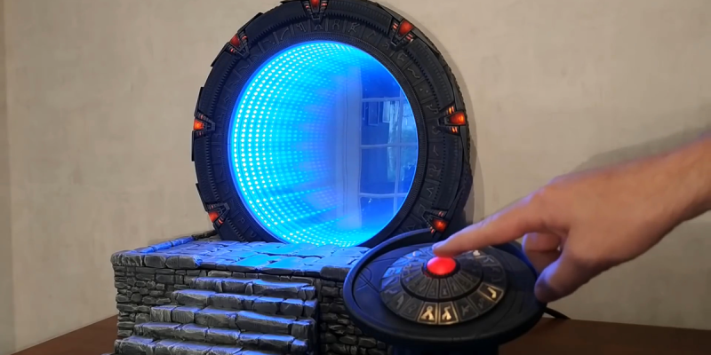

 Its operation is surprisingly simple, in effect a very wideband radio receiver and signal source that can sequentially check signal levels across its range under the control of a microcomputer. On the board is an STM32F103 microcontroller that drives a pair of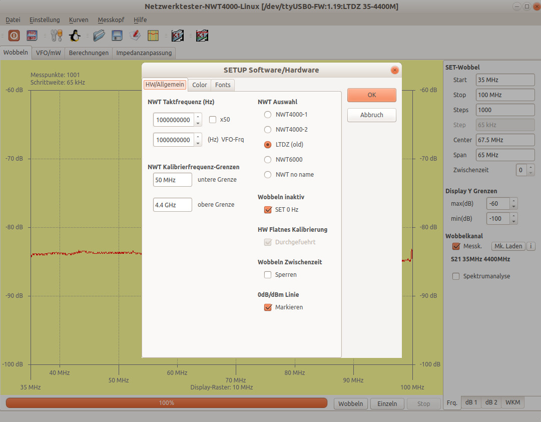
 Well yes… and no. It depends on your reference point. If you look on any topographical map, you’ll notice that elevations are reported in height above (or occasionally, below) sea level. Pilots often report altitudes in AMSL, or Above Mean Sea Level. Mean sea level is obtained by time-averaging the still water level (SWL) to remove cyclical effect of daily tides. SWL is simply what can be measured with a tide gauge, the water level with sea motions such as wind waves smoothed out. This works well enough for measuring the elevation of things that aren’t, well, the ocean, but we run into a problem if we try to measure the ocean in terms of itself. This is where we need other references to measure against.
 Pa). The Mars method won’t work here, since there’s no atmosphere to speak of. To establish the Moon’s reference ellipsoid, scientists determined its average diameter and set that as the zero. The Lunar Reconnaissance Orbiter then can measure the relative altitude of the lunar surface with respect to that datum.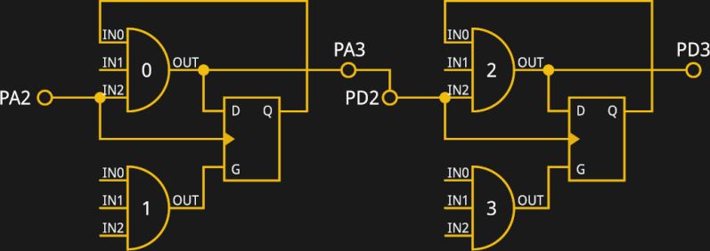
 [rbaron] has shared a string of wireless hacks,