Motor-Driven Movement Modernizes POV Toy

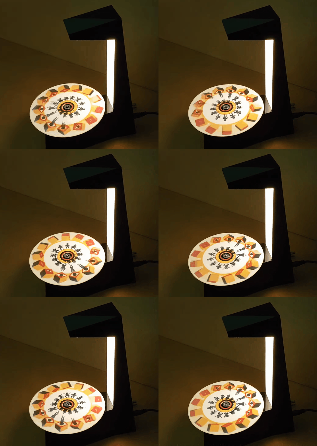
Just as we are driven today to watch gifs that get better with every loop, people 100+ years ago entertained themselves with various persistence of vision toys that used the power of optical illusions to make still images come to life. [jollifactory] recently recreated one of the first POV devices — the phenakistoscope — into a toy for our times.

The original phenakistoscopes were simple, but the effect they achieved was utterly amazing. Essentially a picture disk with a handle, the user would hold the handle with one hand and spin the disk with the other while looking in a mirror through slits in the disk. Unlike the phenakistoscopes of yore that could only be viewed by one person at a time, this one allows for group watching.

Here’s how it works: an Arduino Nano spins a BLDC motor from an old CD-ROM drive, and two strips of strobing LEDs provide the shutter effect needed to make the pictures look like a moving image.The motor speed is both variable and reversible so the animations can run in both directions.

To make the disks themselves, [jollifactory] printed some original phenakistiscopic artwork and adhered each one to a CD that conveniently snaps onto the motor spindle. Not all of the artwork looks good with a big hole in the middle, so [jollifactory] created a reusable base disk with an anti-slip mat on top to spin those.

If you just want to watch the thing in action, check out the first video below that is all demonstration. There be strobing lights ahead, so consider yourself warned. The second and third videos show [jollifactory] soldering up the custom PCB and building the acrylic stand.

There are plenty of modern ways to build old-fashioned POV toys, from all-digital to all-printable.

source https://hackaday.com/2021/02/24/motor-driven-movement-modernizes-pov-toy/

Real-Time OS Basics: Picking The Right RTOS When You Need One

When do you need to use a real-time operating system (RTOS) for an embedded project? What does it bring to the table, and what are the costs? Fortunately there are strict technical definitions, which can also help one figure out whether an RTOS is the right choice for a project.

The “real-time” part of the name namely covers the basic premise of an RTOS: the guarantee that certain types of operations will complete within a predefined, deterministic time span. Within “real time” we find distinct categories: hard, firm, and soft real-time, with increasingly less severe penalties for missing the deadline. As an example of a hard real-time scenario, imagine a system where the embedded controller has to respond to incoming sensor data within a specific timespan. If the consequence of missing such a deadline will break downstream components of the system, figuratively or literally, the deadline is hard.

In comparison soft real-time would be the kind of operation where it would be great if the controller responded within this timespan, but if it takes a bit longer, it would be totally fine, too. Some operating systems are capable of hard real-time, whereas others are not. This is mostly a factor of their fundamental design, especially the scheduler.

In this article we’ll take a look at a variety of operating systems, to see where they fit into these definitions, and when you’d want to use them in a project.

A Matter of Scale

Different embedded OSes address different types of systems, and have different feature sets. The most minimalistic of popular RTOSes is probably FreeRTOS, which provides a scheduler and with it multi-threading primitives including threads, mutexes, semaphores, and thread-safe heap allocation methods. Depending on the project’s needs, you can pick from a number of dynamic allocation methods, as well as only allow static allocation.

On the other end of the scale we find RTOSes such as VxWorks, QNX and Linux with real-time scheduler patches applied. These are generally POSIX-certified or compatible operating systems, which offer the convenience of developing for a platform that’s highly compatible with regular desktop platforms, while offering some degree of real-time performance guarantee, courtesy of their scheduling model.

Again, an RTOS is only and RTOS if the scheduler comes with a guarantee for a certain level of determinism when switching tasks.

Real-Time: Defining ‘Immediately’

Even outside the realm of operating systems, real-time performance of processors can differ significantly. This becomes especially apparent when looking at microcontrollers and the number of cycles required for an interrupt to be processed. For the popular Cortex-M MCUs, for example, the interrupt latency is given as ranging from 12 cycles (M3, M4, M7) to 23+ (M1), best case. Divide by the processor speed, and you’ve got a quarter microsecond or so.

In comparison, when we look at Microchip’s 8051 range of MCUs, we can see in the ‘Atmel 8051 Microcontrollers Hardware Manual’ in section 2.16.3 (‘Response Time’) that depending on the interrupt-configuration, the interrupt latency can be anywhere from 3 to 8 cycles. On x86 platforms the story is more complicated again, due to the somewhat convoluted nature of x86 IRQs. Again, some fraction of a microsecond.

This latency places an absolute bound on the best real-time performance that an RTOS can accomplish, though due to the overhead from running a scheduler, an RTOS doesn’t come close to this bound. This is why, for absolute best-of-class real-time performance, a deterministic single polling loop approach with fast interrupt handler routines for incoming events is by far the most deterministic.

If the interrupt, or other context switch, costs cycles, running the underlying processor faster can also obviously reduce latency, but comes with other trade-offs, not the least of which is the higher power usage and increased cooling requirements.

Adding Some Cool Threads

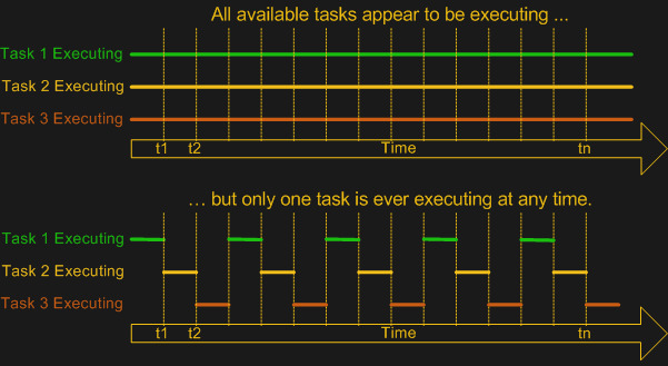
As FreeRTOS demonstrates, the primary point of adding an OS is to add multi-tasking (and multi-threading) support. This means a scheduler module that can use some kind of scheduling mechanism to chop the processor time into ‘slices’ in which different tasks, or threads can be active. While the easiest multi-tasking scheduler is a cooperative-style one, where each thread voluntarily yields to let other threads do their thing, this has the distinct  disadvantage of each thread having the power to ruin everything for other threads.

Most real-time OSes instead use a preemptive scheduler. This means that application threads have no control over when they get to run or for how long. Instead, an interrupt routine triggers the scheduler to choose the next thread for execution, taking care to differentiate between which tasks are preemptable and which are not. So-called kernel routines for example might be marked as non-preemptable, as interrupting them may cause system instability or corruption.

Although both Windows and Linux, in their usual configuration, use a preemptive scheduler, these schedulers are not considered suitable for real-time performance, as they are tuned to prioritize for foreground tasks. User-facing tasks, such as a graphical user interface, will keep operating smoothly even if background tasks may face a shortage of CPU cycles. This is what makes some real-time tasks on desktop OSes such a chore, requiring various workarounds.

A good demonstration of the difference with a real-time focused preemptive scheduler can be found in the x86 version of the QNX RTOS. While this runs fine on an x86 desktop system, the GUI will begin to hang and get sluggish when background tasks are performed, as the scheduler will not give the foreground tasks (the GUI) special treatment. The goal of the Linux kernel’s real-time patch also changes the default behavior of the scheduler to put the handling of interrupts first and foremost, while otherwise not distinguishing between individual tasks unless configured to do so by explicitly setting thread priorities.

RTOS or Not, That’s the Question

At this point it should be clear what is meant by “real-time” and you may have some idea of whether a project would benefit from an RTOS, a plain OS, or an interrupt-driven ‘superloop” approach. There’s no one-size-fits-all answer here, but in general one seeks to strike a balance between the real-time performance required and the available time and budget. Or in the case of a hobby project in far how one can be bothered to optimize it.

The first thing to consider is whether there are any hard deadlines in the project. Imagine you have a few sensors attached to a board that need to be polled exactly at the same intervals and the result written to an SD card. If any kind of jitter in between readings of more than a few dozen cycles would render the results useless, you have a hard real-time requirement of that many cycles.

We know that the underlying hardware (MCU, SoC, etc.) has either a fixed or worst-case interrupt latency. This determines the best-case scenario. In the case of an interrupt-driven single loop approach, we can likely easily meet these requirements, as we can sum up the worst-case interrupt latency, the cycle cost of our interrupt routine (ISR) and the worst-case time it would take to process and write the data to the SD card. This would be highly deterministic.

In the case of our sensors-and-SD-card example, the RTOS version would likely add overhead compared to the single loop version, on account of the overhead from its scheduler. But then imagine that writing to the SD card took a lot of time, and that you wanted to handle infrequent user input as well.

With an RTOS, because the samples need to be taken as close together as possible, you’d want to make this task non-preemptable, and give it a hard scheduling deadline.  The tasks of writing to the SD card and any user input, with a lower priority. If the user has typed a lot, the RTOS might swap back to handling the data collection in the middle of processing strings, for instance, to make a timing deadline. You, the programmer, don’t have to worry about it.

In short: an RTOS offers deterministic scheduling, while an interrupt-driven single loop eliminates the need for scheduling altogether, aside from making sure that your superloop turns around frequently enough.

Creature Comforts

When one pulls away the curtain, it’s obvious that to the processor hardware, concepts like ‘threads’ and thread-synchronization mechanisms such as mutexes and semaphores are merely software concepts that are implemented using hardware features. Deep inside we all know that a single-core MCU isn’t really running all tasks simultaneously when a scheduler performs its multi-tasking duty.

Yet an RTOS – even a minimalistic one like FreeRTOS – allows us to use those software concepts on a platform when we simultaneously need to stay as close to the hardware as possible for performance reasons. Here we strike the balance between performance and convenience, with FreeRTOS leaving us to our own devices when it comes to interacting with the rest of the system. Other RTOSes, like NuttX, QNX and VxWorks offer a full-blown POSIX-compatible environment that supports at least a subset of standard Linux code.

While it’s easy to think of FreeRTOS for example as an RTOS that one would stuff on an MCU, it runs just as well on large SoCs. Similarly, ChibiOS/RT happily runs on anything from an 8-bit AVR MCU to a beefy x86 system. Key here is finding the right balance between the project requirements and what one could call creature comforts that make developing for the target system easier.

For RTOSes that also add a hardware abstraction layer (e.g. ChibiOS, QNX, RT Linux, etc.), the HAL part makes porting between different target systems easier, which can also be considered an argument in its favor. In the end, however, whether to go single loop, simple RTOS, complicated RTOS or ‘just an OS’ is a decision that’s ultimately dependent on the context of the project.

source https://hackaday.com/2021/02/24/real-time-os-basics-picking-the-right-rtos-when-you-need-one/

Real-Time OS Basics: Picking The Right RTOS When You Need One

When do you need to use a real-time operating system (RTOS) for an embedded project? What does it bring to the table, and what are the costs? Fortunately there are strict technical definitions, which can also help one figure out whether an RTOS is the right choice for a project.

The “real-time” part of the name namely covers the basic premise of an RTOS: the guarantee that certain types of operations will complete within a predefined, deterministic time span. Within “real time” we find distinct categories: hard, firm, and soft real-time, with increasingly less severe penalties for missing the deadline. As an example of a hard real-time scenario, imagine a system where the embedded controller has to respond to incoming sensor data within a specific timespan. If the consequence of missing such a deadline will break downstream components of the system, figuratively or literally, the deadline is hard.

In comparison soft real-time would be the kind of operation where it would be great if the controller responded within this timespan, but if it takes a bit longer, it would be totally fine, too. Some operating systems are capable of hard real-time, whereas others are not. This is mostly a factor of their fundamental design, especially the scheduler.

In this article we’ll take a look at a variety of operating systems, to see where they fit into these definitions, and when you’d want to use them in a project.

A Matter of Scale

Different embedded OSes address different types of systems, and have different feature sets. The most minimalistic of popular RTOSes is probably FreeRTOS, which provides a scheduler and with it multi-threading primitives including threads, mutexes, semaphores, and thread-safe heap allocation methods. Depending on the project’s needs, you can pick from a number of dynamic allocation methods, as well as only allow static allocation.

On the other end of the scale we find RTOSes such as VxWorks, QNX and Linux with real-time scheduler patches applied. These are generally POSIX-certified or compatible operating systems, which offer the convenience of developing for a platform that’s highly compatible with regular desktop platforms, while offering some degree of real-time performance guarantee, courtesy of their scheduling model.

Again, an RTOS is only and RTOS if the scheduler comes with a guarantee for a certain level of determinism when switching tasks.

Real-Time: Defining ‘Immediately’

Even outside the realm of operating systems, real-time performance of processors can differ significantly. This becomes especially apparent when looking at microcontrollers and the number of cycles required for an interrupt to be processed. For the popular Cortex-M MCUs, for example, the interrupt latency is given as ranging from 12 cycles (M3, M4, M7) to 23+ (M1), best case. Divide by the processor speed, and you’ve got a quarter microsecond or so.

In comparison, when we look at Microchip’s 8051 range of MCUs, we can see in the ‘Atmel 8051 Microcontrollers Hardware Manual’ in section 2.16.3 (‘Response Time’) that depending on the interrupt-configuration, the interrupt latency can be anywhere from 3 to 8 cycles. On x86 platforms the story is more complicated again, due to the somewhat convoluted nature of x86 IRQs. Again, some fraction of a microsecond.

This latency places an absolute bound on the best real-time performance that an RTOS can accomplish, though due to the overhead from running a scheduler, an RTOS doesn’t come close to this bound. This is why, for absolute best-of-class real-time performance, a deterministic single polling loop approach with fast interrupt handler routines for incoming events is by far the most deterministic.

If the interrupt, or other context switch, costs cycles, running the underlying processor faster can also obviously reduce latency, but comes with other trade-offs, not the least of which is the higher power usage and increased cooling requirements.

Adding Some Cool Threads

As FreeRTOS demonstrates, the primary point of adding an OS is to add multi-tasking (and multi-threading) support. This means a scheduler module that can use some kind of scheduling mechanism to chop the processor time into ‘slices’ in which different tasks, or threads can be active. While the easiest multi-tasking scheduler is a cooperative-style one, where each thread voluntarily yields to let other threads do their thing, this has the distinct  disadvantage of each thread having the power to ruin everything for other threads.

Most real-time OSes instead use a preemptive scheduler. This means that application threads have no control over when they get to run or for how long. Instead, an interrupt routine triggers the scheduler to choose the next thread for execution, taking care to differentiate between which tasks are preemptable and which are not. So-called kernel routines for example might be marked as non-preemptable, as interrupting them may cause system instability or corruption.

Although both Windows and Linux, in their usual configuration, use a preemptive scheduler, these schedulers are not considered suitable for real-time performance, as they are tuned to prioritize for foreground tasks. User-facing tasks, such as a graphical user interface, will keep operating smoothly even if background tasks may face a shortage of CPU cycles. This is what makes some real-time tasks on desktop OSes such a chore, requiring various workarounds.

A good demonstration of the difference with a real-time focused preemptive scheduler can be found in the x86 version of the QNX RTOS. While this runs fine on an x86 desktop system, the GUI will begin to hang and get sluggish when background tasks are performed, as the scheduler will not give the foreground tasks (the GUI) special treatment. The goal of the Linux kernel’s real-time patch also changes the default behavior of the scheduler to put the handling of interrupts first and foremost, while otherwise not distinguishing between individual tasks unless configured to do so by explicitly setting thread priorities.

RTOS or Not, That’s the Question

At this point it should be clear what is meant by “real-time” and you may have some idea of whether a project would benefit from an RTOS, a plain OS, or an interrupt-driven ‘superloop” approach. There’s no one-size-fits-all answer here, but in general one seeks to strike a balance between the real-time performance required and the available time and budget. Or in the case of a hobby project in far how one can be bothered to optimize it.

The first thing to consider is whether there are any hard deadlines in the project. Imagine you have a few sensors attached to a board that need to be polled exactly at the same intervals and the result written to an SD card. If any kind of jitter in between readings of more than a few dozen cycles would render the results useless, you have a hard real-time requirement of that many cycles.

We know that the underlying hardware (MCU, SoC, etc.) has either a fixed or worst-case interrupt latency. This determines the best-case scenario. In the case of an interrupt-driven single loop approach, we can likely easily meet these requirements, as we can sum up the worst-case interrupt latency, the cycle cost of our interrupt routine (ISR) and the worst-case time it would take to process and write the data to the SD card. This would be highly deterministic.

In the case of our sensors-and-SD-card example, the RTOS version would likely add overhead compared to the single loop version, on account of the overhead from its scheduler. But then imagine that writing to the SD card took a lot of time, and that you wanted to handle infrequent user input as well.

With an RTOS, because the samples need to be taken as close together as possible, you’d want to make this task non-preemptable, and give it a hard scheduling deadline.  The tasks of writing to the SD card and any user input, with a lower priority. If the user has typed a lot, the RTOS might swap back to handling the data collection in the middle of processing strings, for instance, to make a timing deadline. You, the programmer, don’t have to worry about it.

In short: an RTOS offers deterministic scheduling, while an interrupt-driven single loop eliminates the need for scheduling altogether, aside from making sure that your superloop turns around frequently enough.

Creature Comforts

When one pulls away the curtain, it’s obvious that to the processor hardware, concepts like ‘threads’ and thread-synchronization mechanisms such as mutexes and semaphores are merely software concepts that are implemented using hardware features. Deep inside we all know that a single-core MCU isn’t really running all tasks simultaneously when a scheduler performs its multi-tasking duty.

Yet an RTOS – even a minimalistic one like FreeRTOS – allows us to use those software concepts on a platform when we simultaneously need to stay as close to the hardware as possible for performance reasons. Here we strike the balance between performance and convenience, with FreeRTOS leaving us to our own devices when it comes to interacting with the rest of the system. Other RTOSes, like NuttX, QNX and VxWorks offer a full-blown POSIX-compatible environment that supports at least a subset of standard Linux code.

While it’s easy to think of FreeRTOS for example as an RTOS that one would stuff on an MCU, it runs just as well on large SoCs. Similarly, ChibiOS/RT happily runs on anything from an 8-bit AVR MCU to a beefy x86 system. Key here is finding the right balance between the project requirements and what one could call creature comforts that make developing for the target system easier.

For RTOSes that also add a hardware abstraction layer (e.g. ChibiOS, QNX, RT Linux, etc.), the HAL part makes porting between different target systems easier, which can also be considered an argument in its favor. In the end, however, whether to go single loop, simple RTOS, complicated RTOS or ‘just an OS’ is a decision that’s ultimately dependent on the context of the project.

source https://hackaday.com/2021/02/24/real-time-os-basics-picking-the-right-rtos-when-you-need-one/

Deleting The Camshafts From A Miata Engine

The idea of camless automotive engines has been around for a while but so far has been limited to prototypes and hypercars. [Wesley Kagan] has been working on a DIY version for a while, and successfully converted a Mazda Miata to a camless valve system. See the videos after the break.

There have been many R&D projects by car manufacturers to eliminate camshafts in order to achieve independent valve timing, but the technology has only seen commercial use on Koenigsegg hypercars. [Wesley] started this adventure on a cheap single cylinder Harbor Freight engine, and proved the basic concept, so he decided to move up to an actual car. He first sourced a junkyard engine head to convert, and use as a drop-in replacement for the head on the complete project car. An off-the-shelf double-acting pneumatic cylinder is mounted over each valve and connected to the valve stem with a custom adaptor. The double-acting cylinder allows the valve to be both opened and closed with air pressure, but [Wesley] still added the light-weight return spring to keep the valve closed if there is any problem with the pneumatic system.

The controller is an Arduino, and it receives a timing signal from a factory crankshaft and operates the pneumatic solenoid valves via MOSFETs. After mounting the new head and control box into the Miata, it took a couple of days of tuning to get the engine running smoothly. Initial tests were done using the compressor in his garage, but this was replaced with a small compressor and air tank mounted in the Miata’s boot for the driving tests.

Although the pneumatic system works well for short test drives, the compressor is quite noisy and adds a couple of points of failure. [Wesley] is also working on a solenoid actuated system, which would require a lot more current from the battery and alternator, but he believes it’s a better long-term solution compared to compressed air. However, he is still struggling to find solenoids with the required specifications.

[Wesley] will be open-sourcing all his designs and code, with the hope that others will be able to modify and improve the design. The results could be very interesting, so we’re hoping a community develops around these camless conversions.

source https://hackaday.com/2021/02/24/deleting-the-camshafts-from-a-miata-engine/

Increasing the Resolution of the Electrical Grid

As a society in the USA and other parts of the world, we don’t give much thought to the twisting vines of civilization that entangle our skies and snake beneath our streets. The humming electrical lines on long poles that string our nations together are simply just there. Ever-present and immutable. We expect to flick the switch and power to come on. We only notice the electrical grid when something goes wrong and there is a seemingly myriad number of ways for things to go wrong. Lighting strikes, trees falling on lines, fires, or even too many people trying to crank on the A/C can all cause rolling blackouts. Or as we found out this month, cold weather can take down generation systems that have not been weatherized.

We often hear the electrical grid described as aging and strained. As we look to the future and at the ever-growing pressure on the infrastructure we take for granted, what does the future of the electrical grid look like? Can we move past blackouts and high voltage lines that criss-cross the country?

Our Current Grid

The power we use in our homes is generated by a complex and dynamic mechanism of peaker plants, distribution nodes, and high voltage lines. We’ve written a guide on how power gets to the outlets in your home as well as a guide trying to demystify the grid as a whole. But a quick recap never hurt anyone.

In our current grid, power starts from some sort of generation source. Usually, this is a large facility such as wind turbine time, a nuclear power plant, or a hydroelectric dam. The power output of the grid must match the load, so it is carefully monitored and controlled. At any one given time, different power sources will be connected to handle the demand, or in the case of Texas over the past week, parts of the grid are shut off so that demand falls to match a reduced capacity.

Some power plants are good at spinning up quickly to meet demand (known as peaker plants) while others are able to produce a steady stream of power. However, some power sources such a wind can’t be “started” if the wind simply isn’t blowing. This is something that large-scale storage efforts like the Hornsdale Power Reserve are seeking to address as they can store power to be used when needed, but grid-scale storage remains a rarity.

Power plants benefit from economies of scale and generate huge amounts of power in a localized area. The tricky part then is getting power to everyone who needs it. Transformers boost 10,000’s volts from the generators to 100,000’s of volts for long-distance transmission. Residential substations step back down to tens of thousands of volts and local transformers take this down to the standard 120/240 volts at a socket.

As cities have rapidly grown, they’ve patched and augmented the grid, with demand and population ballooning faster than construction or budgets allowed. Systems wear out and systems never designed to service that sort of load get expanded upon. It’s a difficult job and the wonderful humans that run and build our grid are working with limited resources.

“Smart” Grids

The future of electrical infrastructure is often declared to be smart grids, without much thought on what the phrase actually means. We’ve talked about how smart the grid really is before on Hackaday. Smart meters are already starting to be rolled out in certain areas, allowing for smarter load shedding and more accurate data. Grid-scale batteries and other storage systems are being installed to help smooth loads and reduce reliance on peaker plants. The industry currently doesn’t have any sort of standard to rally behind so most providers are just experimenting by adding to their existing infrastructure, much as we’ve always done. Adding a solar station here, a local large-scale battery there, and struggling to maintain the millions of miles of electrical lines.

Decentralization

As mentioned before, large-scale power plants have made sense by congregating all the power generation into one place, making it cost-effective to produce, manage, and distribute. However, over the last few decades, we’ve seen a relentless push down in cost due to technological advances and manufacturing scale. The price of solar and wind have plunged ever lower as efficiency has slowly crept up. Solar alone has dropped 70% in price over the last decade.

In fact, the International Renewable Energy Agency (IRENA) released a dataset in June 2020, suggesting that new solar and wind projects are undercutting the cheapest of existing coal-fired plants. The Energy Information Administration (EIA) in the US released a projected LCOE (levelized cost of energy, the price at which the produced electricity must be sold to break even) for 2025 for different power sources. In that data, solar, wind, and geothermal were the best performing in terms of dollars to megawatt-hours.

The EIA also noted that in the future, the share of power generated residentially will continue to grow. Already one-third of solar energy produced is from residential rooftops. So in a world of mini-powerplants scattered across rooftops, what does our grid look like? The Office of Energy Efficiency and Renewable Energy within the Department of Energy (DOE) suggests that a new model might be the way forward. Distributed Energy Resources (DER) and microgrids can come together to form something new. Microgrids can be thought of as a way to further increase the grid size by creating smaller resilient grids within the larger macro grid.

Imagine your neighborhood as a microgrid. Right now, if there was a blackout everyone’s power would be out except for those with a backup generator, solar panels, or some other power solution. With a microgrid, your neighborhood can reconfigure itself and so that any generators or battery packs can power the neighborhood. Even when the macro grid is up and running, your microgrid can lend its power to help smooth power peaks. There’s even the potential of microgrids working together.

The idea seeks to shed the days of massive rolling blackouts when communities can be self-sufficient. By distributing the sources of power across an area rather than congregating them in small clusters, the number of long-distance high-voltage lines could potentially be reduced. Long-distance lines are estimated to cost around $1000 per mega-watt kilometer, so reducing the distance between generation and utilization would lead to significant cost savings for consumers and producers.

Of course, this interconnectivity and two-way coupling between the macro grid and the microgrids creates thousands of new states and edge cases. To help manage a system like this, IEEE has a working proposal for a control scheme for microgrids. While it does take more control out of the hands of large-scale electrical companies and more into the network itself, it provides important features such as prediction and coordination.

Storage

Storage and the intermittent nature are the persistent thorns in the sides of solar and wind power. The sun only shines for part of the day and the wind doesn’t always blow. Traditionally, we simply fire up a peaker plant to match the load as needed. With intermittent power, it needs to be stored and load-shedding algorithms and plans need to be in place.

Despite the up-front costs, storing power offers some unique advantages. Battery banks such as the Hornsdale Power Reserve are quite profitable since they can spin up faster than any gas-powered generator (generally around ten minutes for the gas and nearly instantly for the battery). This allows them to command a premium on the Frequency Control Auxiliary Services (FCAS) market compared to traditional peaker plants.

In addition, power storage can help with “black start” processes, which is the initial kick of power required to start up baseline power plants after an extended blackout. Currently, this is a carefully controlled process of gradually starting larger generators while matching load. Providers have been experimenting with adding storage systems to local areas. While scaling to megawatt scales still presents a challenge, there have been experiments with compressed air, gravity storage, flow batteries, hydro-pumped reservoirs, and dozens of other ideas. Some even suggest using excess power on sunny or windy days to synthesize hydrogen or natural gas, which can be used as storage.

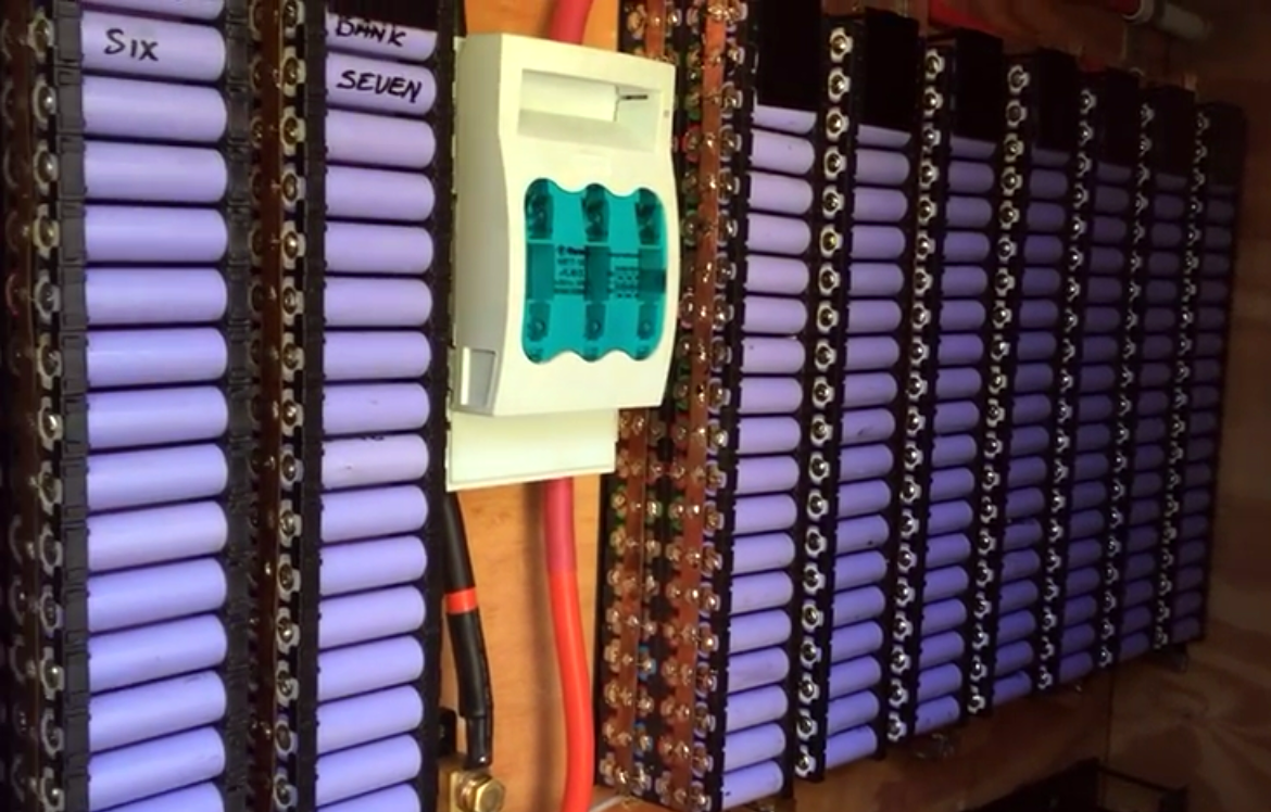
DIY 20 kWh power wall built from 18650 cells by [HBPOwerwall]

So far the trend for microgrids is positive. Every year, a great percentage of solar installs include storage systems instead of just pure solar. By and large, the most common storage solution for residential has been batteries. We’ve written up about adding batteries in a modular way to your home. New battery technologies are on the horizon but for now, most other methods of storing power just don’t make sense in a residential setting. A fun challenge to do with fellow engineers or co-workers is to try and design a power storage system that can be built into a house that doesn’t use batteries while still storing enough power for most of a day (10kWh for example).

As more and more homes and local areas have redundant storage, the microgrid becomes more self-sufficient and capable of withstanding peaks or troughs.

What’s Next

For now, the DoE has determined microgrids are a key part of infrastructure in the common decades. Research programs are ongoing across Europe, Japan, Korea, and Canada. In fact, the Office of Electricity keeps a page of the current microgrid projects here in the USA. While there is still quite a bit to flesh out and standardize, the future does look brighter. We can expect more reliable power with fewer blackouts. Despite all the investments and shifts in grid planning that will come over the next decades, not much will change for the average consumer (which is a good thing). The lights will come on, the fridge will stay cold, and the A/C will blow. Which is perhaps the greatest testament to the incredible system we’ve all built and all rely on.

source https://hackaday.com/2021/02/24/increasing-the-resolution-of-the-electrical-grid/

30 FPS Flip-Dot Display Uses Cool Capacitor Trick

Most people find two problems when it comes to flip-dot displays: where to buy them and how to drive them. If you’re [Pierre Muth] you level up and add the challenge of driving them fast enough to rival non-mechanical displays like LCDs. It was a success, resulting in a novel and fast way of controlling flip-dot displays.

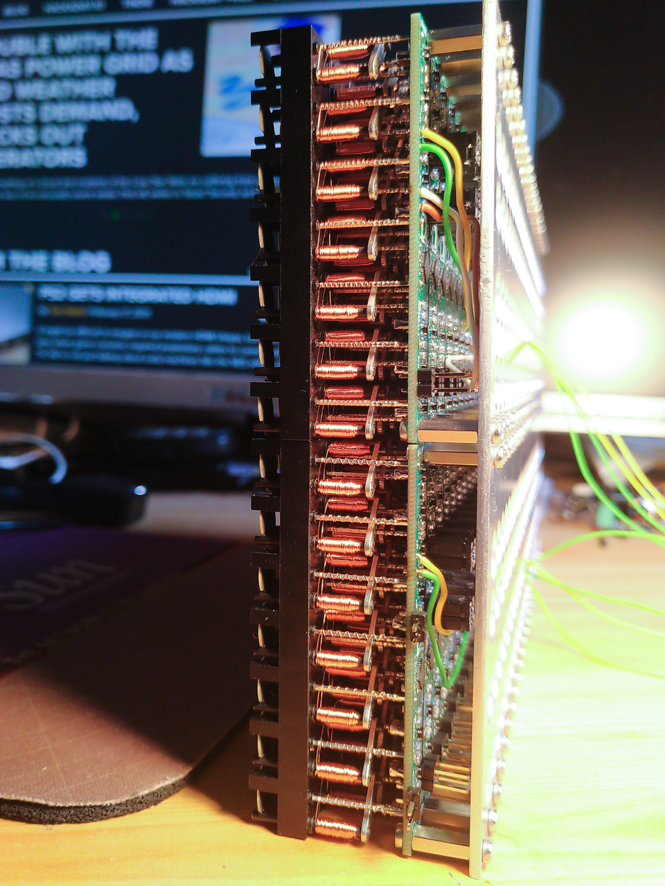
Gorgeous stackup of the completed display. [Pierre] says soldering the 2500 components kept him sane during lockdown.

If you’re lucky, you can get a used flip-dot panel decommissioned from an old bus destination panel, or perhaps the arrivals/departures board at a train station. But it is possible to buy brand new 1×7 pixel strips which is what [Pierre] has done. These come without any kind of driving hardware; just the magnetized dots with coils that can be energized to change the state.

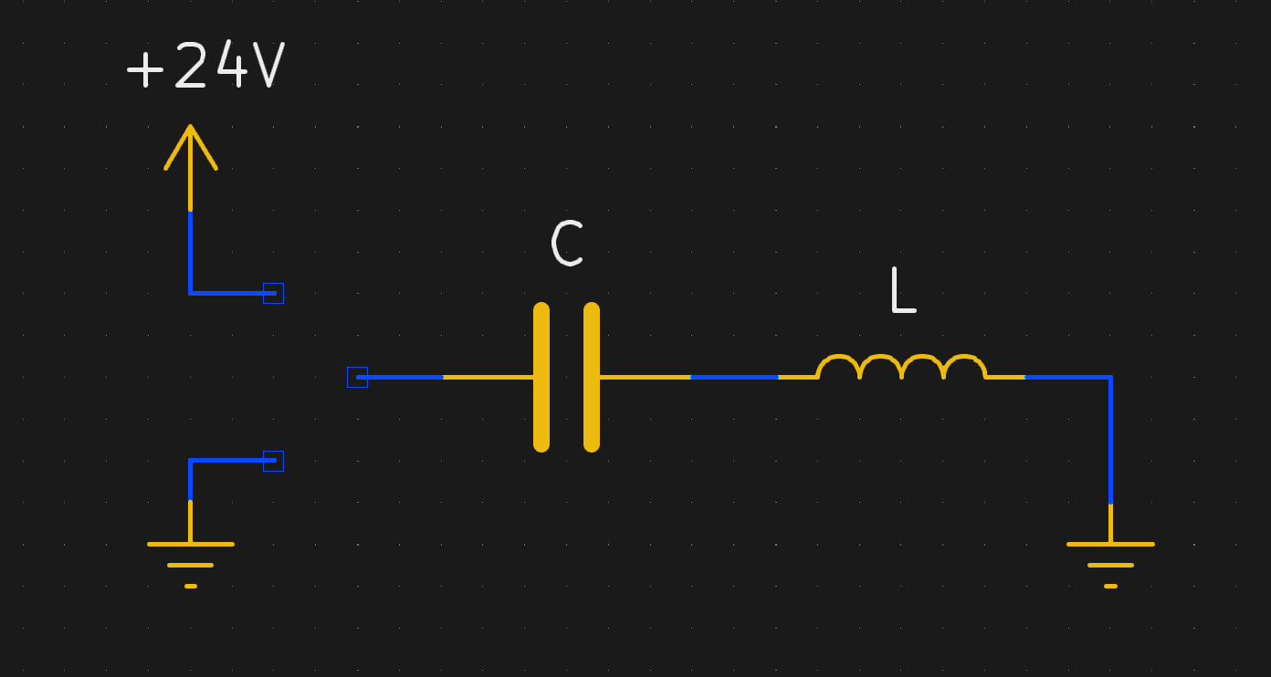
The problem comes in needing to reverse the polarity of the coil to achieve both set and unset states. Here [Pierre] has a very interesting idea: instead of working out a way to change the connections of the coils between source and sink, he’s using a capacitor on one side that can be driven high or low to flip the dot.

Using this technique, charging the capacitor will give enough kick to flip the dot on the display. The same will happen when discharged (flipping the dot back), with the added benefit of not using additional power since the capacitor is already charged from setting the pixel. A circuit board was designed with CMOS to control each capacitor. A PCB is mounted to the back of a 7-pixel strip, creating modules that are formed into a larger display using SPI to cascade data from one to the next. The result, as you can see after the break, does a fantastic job of playing Bad Apple on the 24×14 matrix. If you have visions of one of these on your own desk, the design files and source code are available. Buying the pixels for a display this size is surprisingly affordable at about 100 €.

We’re a bit jealous of all the fun displays [Pierre] has been working on. He previously built a 384 neon bulb display that he was showing off last Autumn.

source https://hackaday.com/2021/02/24/30-fps-flip-dot-display-uses-cool-capacitor-trick/

30 FPS Flip-Dot Display Uses Cool Capacitor Trick

Most people find two problems when it comes to flip-dot displays: where to buy them and how to drive them. If you’re [Pierre Muth] you level up and add the challenge of driving them fast enough to rival non-mechanical displays like LCDs. It was a success, resulting in a novel and fast way of controlling flip-dot displays.

Gorgeous stackup of the completed display. [Pierre] says soldering the 2500 components kept him sane during lockdown.

If you’re lucky, you can get a used flip-dot panel decommissioned from an old bus destination panel, or perhaps the arrivals/departures board at a train station. But it is possible to buy brand new 1×7 pixel strips which is what [Pierre] has done. These come without any kind of driving hardware; just the magnetized dots with coils that can be energized to change the state.

The problem comes in needing to reverse the polarity of the coil to achieve both set and unset states. Here [Pierre] has a very interesting idea: instead of working out a way to change the connections of the coils between source and sink, he’s using a capacitor on one side that can be driven high or low to flip the dot.

Using this technique, charging the capacitor will give enough kick to flip the dot on the display. The same will happen when discharged (flipping the dot back), with the added benefit of not using additional power since the capacitor is already charged from setting the pixel. A circuit board was designed with CMOS to control each capacitor. A PCB is mounted to the back of a 7-pixel strip, creating modules that are formed into a larger display using SPI to cascade data from one to the next. The result, as you can see after the break, does a fantastic job of playing Bad Apple on the 24×14 matrix. If you have visions of one of these on your own desk, the design files and source code are available. Buying the pixels for a display this size is surprisingly affordable at about 100 €.

We’re a bit jealous of all the fun displays [Pierre] has been working on. He previously built a 384 neon bulb display that he was showing off last Autumn.

source https://hackaday.com/2021/02/24/30-fps-flip-dot-display-uses-cool-capacitor-trick/

30 FPS Flip-Dot Display Uses Cool Capacitor Trick

Most people find two problems when it comes to flip-dot displays: where to buy them and how to drive them. If you’re [Pierre Muth] you level up and add the challenge of driving them fast enough to rival non-mechanical displays like LCDs. It was a success, resulting in a novel and fast way of controlling flip-dot displays.

Gorgeous stackup of the completed display. [Pierre] says soldering the 2500 components kept him sane during lockdown.

If you’re lucky, you can get a used flip-dot panel decommissioned from an old bus destination panel, or perhaps the arrivals/departures board at a train station. But it is possible to buy brand new 1×7 pixel strips which is what [Pierre] has done. These come without any kind of driving hardware; just the magnetized dots with coils that can be energized to change the state.

The problem comes in needing to reverse the polarity of the coil to achieve both set and unset states. Here [Pierre] has a very interesting idea: instead of working out a way to change the connections of the coils between source and sink, he’s using a capacitor on one side that can be driven high or low to flip the dot.

Using this technique, charging the capacitor will give enough kick to flip the dot on the display. The same will happen when discharged (flipping the dot back), with the added benefit of not using additional power since the capacitor is already charged from setting the pixel. A circuit board was designed with CMOS to control each capacitor. A PCB is mounted to the back of a 7-pixel strip, creating modules that are formed into a larger display using SPI to cascade data from one to the next. The result, as you can see after the break, does a fantastic job of playing Bad Apple on the 24×14 matrix. If you have visions of one of these on your own desk, the design files and source code are available. Buying the pixels for a display this size is surprisingly affordable at about 100 €.

We’re a bit jealous of all the fun displays [Pierre] has been working on. He previously built a 384 neon bulb display that he was showing off last Autumn.

source https://hackaday.com/2021/02/24/30-fps-flip-dot-display-uses-cool-capacitor-trick/

Audio Out Over A UART With An FTDI USB-To-TRS Cable

What is the easiest way to get audio from a WAV file into a line-level format, ready to be plugged into the amplifier of a HiFi audio set (or portable speaker)? As [Konrad Beckmann] demonstrated on Twitter, all you really need is a UART, a cable and a TRS phono plug. In this case a USB-TTL adapter based around the FTDI FT232R IC: the TTL-232R-3V3-AJ adapter with 12 Mbps USB on one end, and a 3 Mbps UART on the other end.

[Konrad] has made the C-based code available on GitHub. Essentially what happens underneath the hood is that it takes in a PCM-encoded file (e.g. WAV). As a demonstration project, it requires the input PCM files to be a specific sample rate, as listed in the README, which matches the samples to the baud rate of the UART. After this it’s a matter of encoding the audio file, and compiling the uart-sound binary.

The output file is the raw audio data, which is encoded in PDM, or Pulse-Density Modulation. Unlike Pulse-Code Modulation (PCM), this encoding method does not encode the absolute sample value, but uses binary pulses, the density of which corresponds to the signal level. By sending PDM data down the UART’s TX line, the other side will receive these bits. If said receiving device happens to be an audio receiver with an ADC, it will happily receive and play back the PDM signal as audio. As one can hear in the video embedded in the tweet, the end result is pretty good.


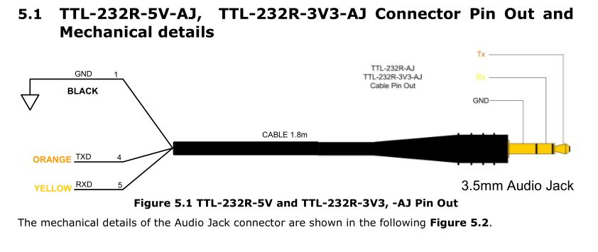
If we look at at the datasheet for the TTL-232R-3V3-AJ adapter cable, we can see how it is wired up:

When we compare this to the wiring of a standard audio TRS jack, we can see that the grounds match in both wirings, and TX (RX on the receiving device) would match up with the left channel, with the right channel unused. A note of caution here is also required: this is the 3.3V adapter version, and it lists its typical output high voltage as 2.8V, which is within tolerances for line-level inputs. Not all inputs will be equally tolerant of higher voltages, however.

Plugging random TRS-equipped devices into one’s HiFi set, phone or boombox is best done only after ascertaining that no damage is likely to result.  Be safe, and enjoy the music.

source https://hackaday.com/2021/02/24/audio-out-over-a-uart-with-an-ftdi-usb-to-trs-cable/

Retro Dreamcast Rhythm Game Controller Built From Scratch

Pop’n Music is a rhythm game which has had both arcade and home console releases over the years. [Charlie Cole] is a fan of the Dreamcast version, and decided to build his own controller for the game using the new hotness, the Raspberry Pi Pico.

The controller itself is built out of layers of lasercut MDF, along with an acrylic top and cork bottom to make it sit nicely on surfaces. Arcade buttons are installed to play the rhythm game, mimicking the design of the official cabinets seen in arcades. To run the controller, a Pico was pressed into service, with [Charlie] hoping to use the Pico’s PIO hardware to easily and effectively interface with the Dreamcast’s Maple bus. There were a few headaches along the way, and it didn’t quite live up to expectations, but with some clever use of dual cores, [Charlie] was able to get everything up and running.

Often, such vintage gaming hardware can be thin on the ground, so having the skills to build your own can come in handy. We’ve seen rhythm game hardware modded before too, like this repurposed DJ Hero controller. Video after the break.

source https://hackaday.com/2021/02/23/retro-dreamcast-rhythm-game-controller-built-from-scratch/

Capstan Winch Central to This All-Band Adjustable Dipole Antenna

The perfect antenna is the holy grail of amateur radio. But antenna tuning is a game of inches, and since the optimum length of an antenna depends on the frequency it’s used on, the mere act of spinning the dial means that every antenna design is a compromise. Or perhaps not, if you build this infinitely adjustable capstan-winch dipole antenna.

Dipoles are generally built to resonate around the center frequency of one band, and with allocations ranging almost from “DC to daylight”, hams often end up with a forest of dipoles. [AD0MZ]’s adjustable dipole solves that problem, making the antenna usable from the 80-meter band down to 10 meters. To accomplish this feat it uses something familiar to any sailor: a capstan winch.

The feedpoint of the antenna contains a pair of 3D-printed drums, each wound with a loop of tinned 18-gauge antenna wire attached to some Dacron cord. These make up the adjustable-length elements of the antenna, which are strung through pulleys suspended in trees about 40 meters apart. Inside the feedpoint enclosure are brushes from an electric drill to connect the elements to a 1:1 balun and a stepper motor to run the winch. As the wire pays out of one spool, the Dacron cord is taken up by the other; the same thing happens on the other side of the antenna, resulting in a balanced configuration.

We think this is a really clever design that should make many a ham happy across the bands. We even see how this could be adapted to other antenna configurations, like the end-fed halfwave we recently featured in our “$50 Ham” series.

source https://hackaday.com/2021/02/23/capstan-winch-central-to-this-all-band-adjustable-dipole-antenna/

dodowDIY Is A Homebrew Sleep Aid

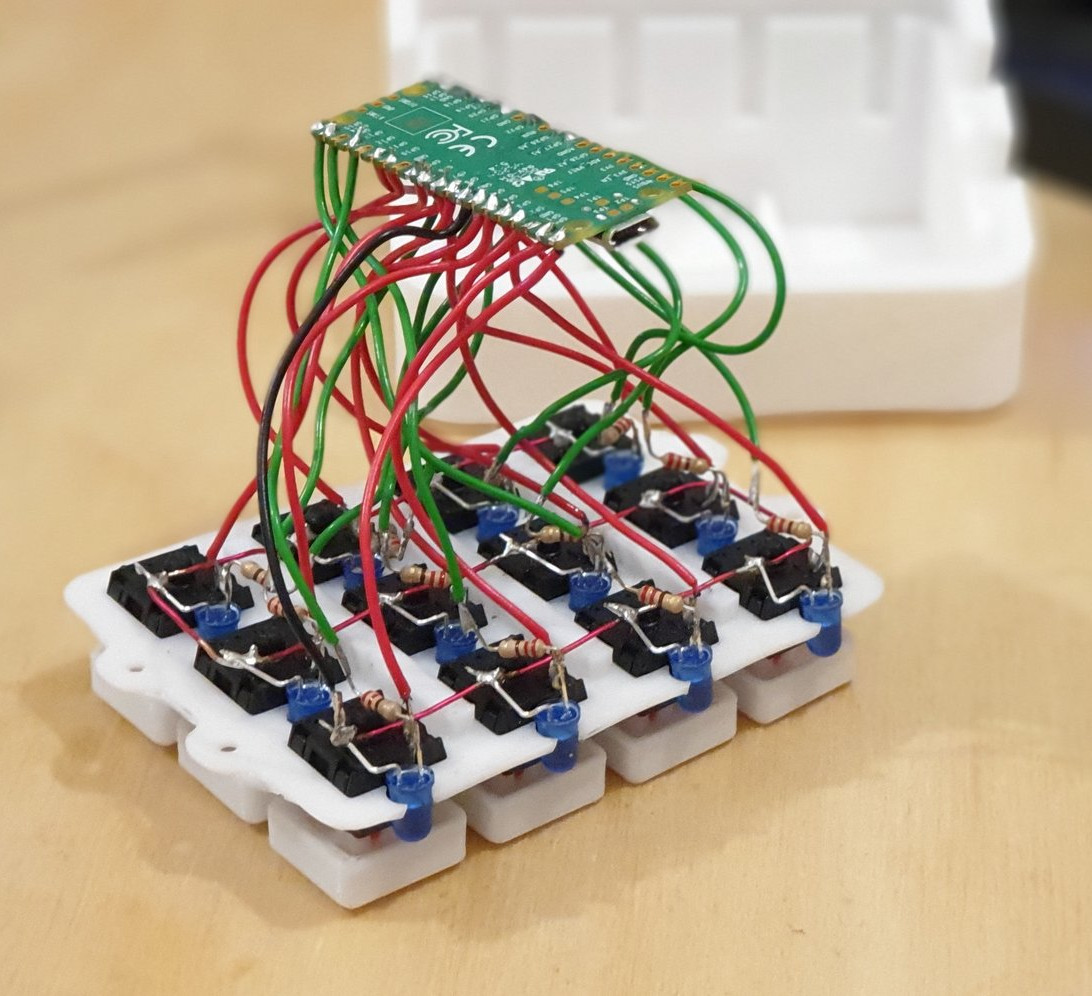
The Dodow is a consumer device that aims to help users sleep, through biofeedback. The idea is to synchronise one’s breathing with the gentle rhythm of the device’s blue LEDs, which helps slow the heartrate and enables the user to more easily drift off to sleep. Noting that the device is essentially a breathing LED and little more, [Daniel Shiffman] set about building his own from scratch.

An ATTiny85 runs the show; no high-powered microcontrollers are necessary here. It’s hooked up to three 5mm blue LEDs, which are slowly ramped up and down to create a smooth, attractive breathing animation. The LEDs are directed upward so that their glow can be seen on the ceiling, allowing the user to lay on their back when getting ready for sleep. It’s all wrapped up in a 3D printed enclosure that is easily modifiable to suit a variety of battery solutions; [Daniel] chose the DL123A for its convenient voltage and battery life in this case. The design is available on Thingiverse for those looking to spin their own.

It’s a neat example of where DIY can really shine – reproducing a somewhat-expensive gadget that is overpriced for its fundamental simplicity. Now when it comes to waking up again, consider building yourself a nifty smart alarm clock.

source https://hackaday.com/2021/02/23/dodowdiy-is-a-homebrew-sleep-aid/

Ben Krasnow Measures Human Calorie Consumption By Collecting The “Output”

It’s a bit icky reading between the lines on this one… but it’s a fascinating experiment! In his latest Applied Science video, [Ben Krasnow] tries to measure how efficient the human body is at getting energy from food by accurately measuring what he put in and what comes out of his body.

The jumping off point for this experiment is the calorie count on the back of food packaging. [Ben] touches on “bomb calorimetry” — the process of burning foodstuff in an oxygen-rich environment and measuring the heat given off to establish how much energy was present in the sample. But our bodies are flameless… can we really extract similar amounts of energy as these highly controlled combustion chambers? His solution is to measure his body’s intake by eating nothing but Soylent for a week, then subjects his body’s waste to the bomb calorimetry treatment to calculate how much energy was not absorbed during digestion. (He burned his poop for science, and made fun of some YouTubers at the same time.)

The test apparatus is a cool build — a chunk of pipe with an acrylic/glass laminated window that has a bicycle tire value for pressurization, a pressure gauge, and electrodes to spark the combustion using nichrome wire and cotton string. It’s shown above, burning a Goldfish® cracker but it’s not actually measuring the energy output as this is just a test run. The actual measurements call for the combustion chamber to be submerged in an insulated water bath so that the temperature change can be measured.

Now to the dirty bits. [Ben] collected fecal matter and freeze-dried it to ready it for the calorimeter. His preparation for the experiment included eating nothing but Soylent (a powdered foodstuff) to achieve an input baseline. The problem is that he measures the fecal matter to have about 75% of the calories per gram compared to the Soylent. Thinking on it, that’s not surprising as we know that dung must have a high caloric level — it burns and has been used throughout history as a source of warmth among other things. But the numbers don’t lead to an obvious conclusion and [Ben] doesn’t have the answer on why the measurements came out this way. In the YouTube comments [Bitluni] asks the question that was on our minds: how do you correlate the volume of the input and output? Is comparing 1g of Soylent to 1g of fecal matter a correct equivalency? Let us know what you think the comments below.

The science of poop is one of those 8th-grade giggle topics, but still totally fascinating. Two other examples that poop to mind are our recent sewage maceration infrastructure article and the science of teaching robot vacuums to detect pet waste.

source https://hackaday.com/2021/02/23/ben-krasnow-measures-human-calorie-consumption-by-collecting-the-output/

Paul Taylor Opened the Lines of Telecommunication for the Hearing-Impaired

These days, nearly everyone communicates through some kind of keyboard, whether they are texting, emailing, or posting on various internet discussion forums. Talking over the phone is almost outmoded at this point. But only a few decades ago, the telephone was king of real-time communication. It was and still is a great invention, but unfortunately the technology left the hearing and speaking-impaired communities on an island of silence.

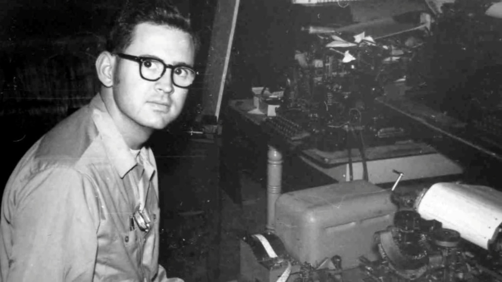
Paul and an early TDD. Image via Rochester Institute of Technology

Engineer and professor Paul Taylor was born deaf in 1939, long before cochlear implants or the existence of laws that called for testing and early identification of hearing impairment in infants. At the age of three, his mother sent him by train to St. Louis to live at a boarding school called the Central Institute for the Deaf (CID).

Here, he was outfitted with a primitive hearing aid and learned to read lips, speak, and use American sign language. At the time, this was the standard plan for deaf and hearing-impaired children — to attend such a school for a decade or so and graduate with the social and academic tools they needed to succeed in public high schools and universities.

After college, Paul became an engineer and in his free time, a champion for the deaf community. He was a pioneer of Telecommunications Devices for the Deaf, better known as TDD or TTY equipment in the US. Later in life, he helped write legislation that became part of the 1990 Americans with Disabilities Act.

Paul was diagnosed with Alzheimer’s in 2017 and died in January of 2021 at the age of 81. He always believed that the more access a deaf person had to technology, the better their life would be, and spent much of his life trying to use technology to improve the deaf experience.

High school-aged Paul. Image via YouTube

Learning to Speak Without Hearing

Soon after three-year-old Paul started school at CID, he met a little girl named Sally Hewlett who would one day become his wife. Along with their classmates, they spent the next several years learning to speak by holding their hands to the teacher’s face to feel the vibrations of speech, then touching their own faces while mimicking the movement and sound.

Paul’s father died while he was still in school. His mother moved to St. Louis to be with her son so he could still attend, but live at home. She took the opportunity to study at CID and she became an accredited teacher for deaf children. When it was time for high school, Paul and his mother moved to Houston, where she started a school for the deaf, and he enrolled in public school for the first time. Paul had no interpreter, no helper of any kind.

In a 2007 documentary made by the Taylors’ youngest daughter, Paul tells a story about an experience he had in high school. There was a nice looking girl in his class, and he wanted to know more about her, so he asked a different girl who she was. When that girl offered to give Paul the first girl’s telephone number, he stopped in his tracks, realizing at that moment how different he was because he couldn’t use the phone like all the other kids. The experience stuck with him and helped drive his life’s work.

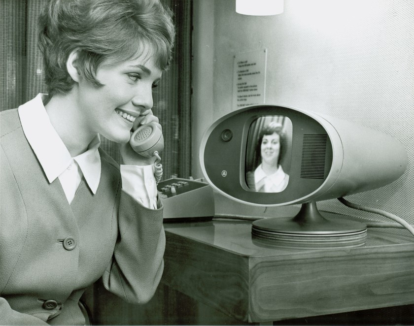
AT&T’s Picturephone as it premiered at the 1964 World’s Fair. Image source: AT&T Archives and History Center via LA Times

Phones for All

After high school, Paul completed his bachelor’s of chemical engineering degree from the Georgia Institute of Technology in 1962 and moved back to St. Louis to earn a master’s degree in operational research at Washington University. In the meantime, Sally, who had gone to high school in St. Louis, earned her bachelor’s degree in home economics and returned to CID to teach physical education, religion, and home economics. When Paul learned that Sally was living in town, he got in touch with her immediately. They started dating and were engaged six months later.

Paul took Sally to the 1964 World’s Fair in Queens, New York for their first anniversary. They marveled at AT&T’s Picturephone and wished the future would arrive sooner so they could easily talk from anywhere by reading each other’s lips. By day, Paul was an engineer at McDonnell Douglas and later, Monsanto. He was a different kind of engineer at home, devising different ways to help raise their three hearing children. After their first child was born, Paul built a system that would blink the lights in the house to let them know the baby was crying.

Paul, Sally, and their son David along with one of the first teletypewriters that was repurposed as a telecommunication device for the deaf. Image via Rochester Institute of Technology

He also did whatever he could to help the deaf community by volunteering his time. The phone problem still bothered him greatly. When he noticed an old Western Union teletype machine from WWII just sitting around collecting dust, he got the idea to turn it into a new kind of communication tool.

Around the same time, a deaf physicist named Robert Weitbrecht was developing an acoustic coupler that would transmit teletype signals over consumer phone lines. Paul got Weitbrecht to send him one and created one of the first telecommunication devices for the deaf (TDD). With one of these devices on each end of the phone line, anything typed on one would be printed out on the other. Paul worked with Western Union to get these old teletypewriters into the hands of hearing and speaking-impaired people, and convinced AT&T to create a relay service to use them as well.

Paul started a non-profit organization to distribute these early TDDs to other deaf St. Louisans. He asked a local telephone wake-up call service to help out, and built one of the first telephone relay systems in the process. Although both parties needed a TDD to be able to communicate, this was a big step in the right direction.

Paul also did a lot of work to keep the machines humming for the people who depended on them. Teletypewriter manuals were helpful, but were awfully dense reading material for the layman. Paul organized a week-long workshop to create a picture-rich manual called Teletypewriters Made Easy to help people repair and maintain three common models of teletypewriter. Paul discusses his personal history with TDD development in the video below.

A Loud Voice for the Deaf Community

In 1975, Paul was offered a position at the National Institute for the Deaf at Rochester Institute of Technology, so the Taylor family moved to upstate New York. Paul became a computer technology professor and chairman of the Engineering Support team. He stayed there for the next 30 years before retiring.

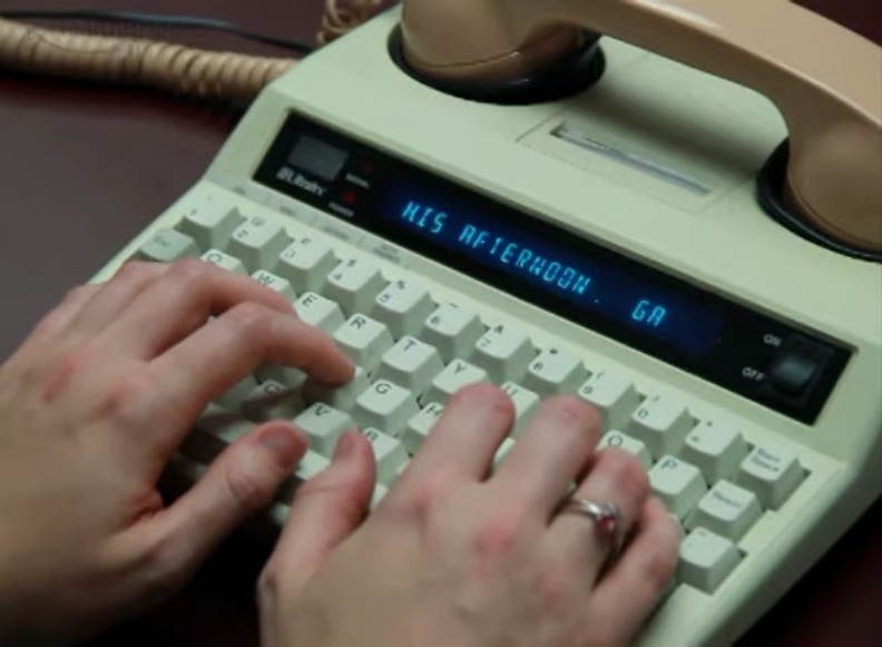
A more modern TTY. Image via YouTube

During this time, he advocated for a national, operator-assisted telephone relay service through which deaf and hearing impaired people could communicate with anyone, whether or not the other person had a TDD.

The idea was that the deaf person would use a TTY to call an operator, who would get the other person on the line and relay messages back and forth between the two parties by typing out what the voice caller said and reading aloud what the TDD user typed in response. Paul took a two-year leave of absence from teaching and worked directly with the FCC to write regulations that became part of the guidelines prescribed in the 1990 Americans with Disabilities Act (ADA).

Learning How to Hear

At the age of 65, Paul and Sally decided to get cochlear implants after a lifetime of silence. Their youngest daughter Irene made a documentary about their experience called Hear and Now, which is embedded below. It’s an interesting firsthand look into the process, which is not the instant cure that the internet may have led you to believe. The implant can’t be activated until the swelling from surgery goes down, which takes about a month. And it can take years for the brain to get used the new sensory information and begin to distinguish relevant sounds from background noise.

Although TTY/TDDs are falling out of use thanks to the videophone-enabled text messaging devices in most people’s pockets, their influence on communication lives on in shorthand now used in our everyday messages — OIC, PLS, and THX are older than you might think.

Thanks for the tip, [Zoobab].

source https://hackaday.com/2021/02/23/paul-taylor-opened-the-lines-of-telecommunication-for-the-hearing-impaired/

Paul Taylor Opened the Lines of Telecommunication for the Hearing-Impaired

These days, nearly everyone communicates through some kind of keyboard, whether they are texting, emailing, or posting on various internet discussion forums. Talking over the phone is almost outmoded at this point. But only a few decades ago, the telephone was king of real-time communication. It was and still is a great invention, but unfortunately the technology left the hearing and speaking-impaired communities on an island of silence.

Paul and an early TDD. Image via Rochester Institute of Technology

Engineer and professor Paul Taylor was born deaf in 1939, long before cochlear implants or the existence of laws that called for testing and early identification of hearing impairment in infants. At the age of three, his mother sent him by train to St. Louis to live at a boarding school called the Central Institute for the Deaf (CID).

Here, he was outfitted with a primitive hearing aid and learned to read lips, speak, and use American sign language. At the time, this was the standard plan for deaf and hearing-impaired children — to attend such a school for a decade or so and graduate with the social and academic tools they needed to succeed in public high schools and universities.

After college, Paul became an engineer and in his free time, a champion for the deaf community. He was a pioneer of Telecommunications Devices for the Deaf, better known as TDD or TTY equipment in the US. Later in life, he helped write legislation that became part of the 1990 Americans with Disabilities Act.

Paul was diagnosed with Alzheimer’s in 2017 and died in January of 2021 at the age of 81. He always believed that the more access a deaf person had to technology, the better their life would be, and spent much of his life trying to use technology to improve the deaf experience.

High school-aged Paul. Image via YouTube

Learning to Speak Without Hearing

Soon after three-year-old Paul started school at CID, he met a little girl named Sally Hewlett who would one day become his wife. Along with their classmates, they spent the next several years learning to speak by holding their hands to the teacher’s face to feel the vibrations of speech, then touching their own faces while mimicking the movement and sound.

Paul’s father died while he was still in school. His mother moved to St. Louis to be with her son so he could still attend, but live at home. She took the opportunity to study at CID and she became an accredited teacher for deaf children. When it was time for high school, Paul and his mother moved to Houston, where she started a school for the deaf, and he enrolled in public school for the first time. Paul had no interpreter, no helper of any kind.

In a 2007 documentary made by the Taylors’ youngest daughter, Paul tells a story about an experience he had in high school. There was a nice looking girl in his class, and he wanted to know more about her, so he asked a different girl who she was. When that girl offered to give Paul the first girl’s telephone number, he stopped in his tracks, realizing at that moment how different he was because he couldn’t use the phone like all the other kids. The experience stuck with him and helped drive his life’s work.

AT&T’s Picturephone as it premiered at the 1964 World’s Fair. Image source: AT&T Archives and History Center via LA Times

Phones for All

After high school, Paul completed his bachelor’s of chemical engineering degree from the Georgia Institute of Technology in 1962 and moved back to St. Louis to earn a master’s degree in operational research at Washington University. In the meantime, Sally, who had gone to high school in St. Louis, earned her bachelor’s degree in home economics and returned to CID to teach physical education, religion, and home economics. When Paul learned that Sally was living in town, he got in touch with her immediately. They started dating and were engaged six months later.

Paul took Sally to the 1964 World’s Fair in Queens, New York for their first anniversary. They marveled at AT&T’s Picturephone and wished the future would arrive sooner so they could easily talk from anywhere by reading each other’s lips. By day, Paul was an engineer at McDonnell Douglas and later, Monsanto. He was a different kind of engineer at home, devising different ways to help raise their three hearing children. After their first child was born, Paul built a system that would blink the lights in the house to let them know the baby was crying.

Paul, Sally, and their son David along with one of the first teletypewriters that was repurposed as a telecommunication device for the deaf. Image via Rochester Institute of Technology

He also did whatever he could to help the deaf community by volunteering his time. The phone problem still bothered him greatly. When he noticed an old Western Union teletype machine from WWII just sitting around collecting dust, he got the idea to turn it into a new kind of communication tool.

Around the same time, a deaf physicist named Robert Weitbrecht was developing an acoustic coupler that would transmit teletype signals over consumer phone lines. Paul got Weitbrecht to send him one and created one of the first telecommunication devices for the deaf (TDD). With one of these devices on each end of the phone line, anything typed on one would be printed out on the other. Paul worked with Western Union to get these old teletypewriters into the hands of hearing and speaking-impaired people, and convinced AT&T to create a relay service to use them as well.

Paul started a non-profit organization to distribute these early TDDs to other deaf St. Louisans. He asked a local telephone wake-up call service to help out, and built one of the first telephone relay systems in the process. Although both parties needed a TDD to be able to communicate, this was a big step in the right direction.

Paul also did a lot of work to keep the machines humming for the people who depended on them. Teletypewriter manuals were helpful, but were awfully dense reading material for the layman. Paul organized a week-long workshop to create a picture-rich manual called Teletypewriters Made Easy to help people repair and maintain three common models of teletypewriter. Paul discusses his personal history with TDD development in the video below.

A Loud Voice for the Deaf Community

In 1975, Paul was offered a position at the National Institute for the Deaf at Rochester Institute of Technology, so the Taylor family moved to upstate New York. Paul became a computer technology professor and chairman of the Engineering Support team. He stayed there for the next 30 years before retiring.

A more modern TTY. Image via YouTube

During this time, he advocated for a national, operator-assisted telephone relay service through which deaf and hearing impaired people could communicate with anyone, whether or not the other person had a TDD.

The idea was that the deaf person would use a TTY to call an operator, who would get the other person on the line and relay messages back and forth between the two parties by typing out what the voice caller said and reading aloud what the TDD user typed in response. Paul took a two-year leave of absence from teaching and worked directly with the FCC to write regulations that became part of the guidelines prescribed in the 1990 Americans with Disabilities Act (ADA).

Learning How to Hear

At the age of 65, Paul and Sally decided to get cochlear implants after a lifetime of silence. Their youngest daughter Irene made a documentary about their experience called Hear and Now, which is embedded below. It’s an interesting firsthand look into the process, which is not the instant cure that the internet may have led you to believe. The implant can’t be activated until the swelling from surgery goes down, which takes about a month. And it can take years for the brain to get used the new sensory information and begin to distinguish relevant sounds from background noise.

Although TTY/TDDs are falling out of use thanks to the videophone-enabled text messaging devices in most people’s pockets, their influence on communication lives on in shorthand now used in our everyday messages — OIC, PLS, and THX are older than you might think.

Thanks for the tip, [Zoobab].

source https://hackaday.com/2021/02/23/paul-taylor-opened-the-lines-of-telecommunication-for-the-hearing-impaired/

Useful Build Tips For Making LED Panel Frames

[NotLikeALeafOnTheWind] has created many LED-based display projects, and shares his method for making attractive LED panel frames and mounts. At first glance it may look as though slapping a rectangle of aluminum extrusion around a display is all it takes, there is also the mounting and management of wiring, power supply, and possibly a Raspberry Pi to deal with. The process of building an attractive frame also has a few hidden gotchas that can be avoided with a bit of careful planning.

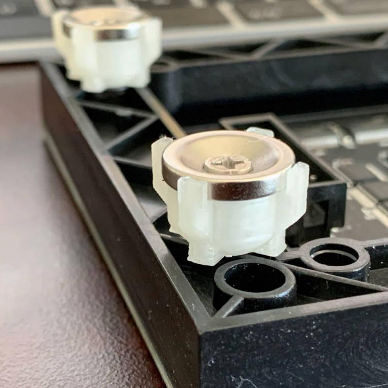
Magnetic feet on the LED panels makes mounting much easier and more flexible.

Here is one tip that will resonate with some readers: don’t rely on specified dimensions of parts; measure the actual parts yourself. There can be small differences between what a data sheet says to expect, and the dimensions of the actual part in one’s hands. It may not be much, but it can be the difference between an ideal fit, and something that looks like a bit of a hack job.

[NotLikeALeafOnTheWind] provides some basic frame layouts, and suggests using two- or three-channel extrusions to provide a flat bezel around the display edge if desired. Mounting the LED panel itself is done with magnetic feet and providing a length of steel bar to which the display can attach. This can provide a flush mount while avoiding the whole issue of screw-mounting the display panels themselves, or sliding them into channels. For mounting all the other hardware, a piece of DIN rail and some 3D-printed parts takes care of that.

The result looks slick and sturdy, and some of the tips are sure to be useful even if the whole process isn’t applied. We like the way the basic design scales and is flexible about the thickness and size of the LED panels themselves, making it a promising way to accommodate perfectly functional oddball panels that end up in the trash.

source https://hackaday.com/2021/02/23/useful-build-tips-for-making-led-panel-frames/

Hands on With the Ortur Laser Cutter

I couldn’t write very much without a computer. Early in my career, I wrote with a typewriter. Unless you are pretty close to perfect — I’m not — it is very frustrating to make edits on typewritten stuff. The equivalent in the real world, for me, has been 3D printers and CNC machines. I can visualize a lot of things that I’m not careful enough to build with normal tools. Despite my 7th-grade shop teacher’s best efforts, everything I did turned out to be a toothpick or a number 7. But I can get my ideas into CAD and from there the machines do the rest. That’s why I was excited to get a laser cutter this past Christmas. You might wonder why I’d need a laser cutter if I have the other tools. Then again, if you read Hackaday, you probably don’t need me to explain why you need a new gadget. I’ve had my eye on a laser for a good long time, but recent developments made it more attractive. I thought I’d share with you some of what I’ve found getting started with the Ortur laser cutter. The cutter is easy to put together and costs somewhere in the $200-$400 range depending on what you get with it. I thought I’d take some time to share what I’ve learned about it.

Why a Laser?

If you haven’t had experience with a laser cutter or engraver before, you might think it is a very specific instrument. Sure, the Ortur is good at engraving some things (but not all things). It can cut some things, too, but not as many things as a big serious laser cutter. However, creative people find lots of ways to use cutting and engraving to produce things you might not expect.

For example, if you surf YouTube, you’ll find people who put spray paint on either a ceramic tile or a canvas and then burn some or all of the paint away to make really interesting artwork. Sometimes they’ll even use multiple layers of paint to create different colors by burning different depths into the artwork. Another multicolor technique is to cut what amounts to a custom stencil in masking tape that is already applied to the part. You can then spray paint, remove the tape, apply fresh tape, and cut a new stencil for another color. Some people etch the backs of mirrors. It is also surprisingly handy to be able to precision cut paper and cardboard. However, with some practice and technique, you can even cut some thicknesses of plywood.

I’m very interested in creating PC boards either directly or by cutting resist and then using conventional etching techniques. People are doing that, too. Depending on the power of your laser, you can cut quite a few things, although with a visible laser, you can’t cut things that are transparent. You can engrave more things, and even metal if you use some additional chemicals (like mustard). In addition to line art and text, you can do halftone images from pictures. If you have a powerful enough laser, you can even make glass, sort of.

Of course, in addition to all the artsy things, you can just cut material too, which is surprisingly handy. [Electronoobs] did a video last year experimenting with different materials with a 15W laser so that will give you some idea of what you can and can’t cut with this type of laser.

There are some things you shouldn’t cut because they emit noxious fumes like ABS or vinyl products. Leather engraves and cuts well but boy does it stink! I understand that you should be careful working with chrome tanned leather, too, because the tanning chemicals could emit bad fumes. Some materials are also too prone to bursting into flames like styrofoam.

About the Ortur

If you want a laser, your next problem is which one to buy. There are carbon dioxide lasers that are commonly available, but they are pretty pricey and are known to need a lot of effort — including a bucket of ice of water and ventilation — to use. Semiconductor lasers are cheap and much easier to use. These are generally visible which, as I mentioned, means you can’t use them to cut some things like clear acrylic. You can get some very inexpensive laser engravers, but many of them are probably not going to cut much.

Then again, power isn’t everything. Broadly speaking, you can trade time for power with a laser. That is, a cut that might take a 10 watt laser a few seconds in a single pass might take a 1 watt laser four or five 30-second passes. It isn’t always simple because as the laser chars material it creates a barrier that prevents you from getting as much energy underneath. Still, you can sometimes do the same job with lower power if you are willing to take longer per pass and repeat the pass.

The Ortur Laser Master 2 is reasonably priced and has three choices in laser power: 7W, 15W, and 20W. This is a little deceptive because the power is actually the input power to the module. The 15W unit, for example, produces less than 5W of output power, but that’s still able to do a lot more than you might think.

The device is made to work with a free piece of Windows software called LaserGRBL that talks to the onboard GRBL controller. In theory, anything that would send G-code could work. I use Linux, so I opted for LightBurn which is excellent and well worth the $40 you’ll pay for it. It runs on multiple platforms, too, but sadly not on the Raspberry Pi, so I’ve had to drag a laptop out to work with the Ortur. You might also check out LaserWeb.

There are other cheap laser engravers and cutters, but I was impressed with the Ortur’s size and capabilities. There’s also a lot of add on designs available for it and good support in software.

Assembly

The unit requires some assembly, although much of it is preassembled. You build a frame of aluminum extrusions and then slip the X carriage on. There’s a 32-bit controller board and some stepper motors. The 32-bit board is a big selling point. Some of the work you do with the laser requires PWM to modulate the beam’s power. Most 8-bit boards will allow you to step power from 0-255 so each step is about 0.4% of full strength. A 32-bit board will let you do around 1,000 divisions of full scale which gives you about 0.1% on each step.

The mechanism is like a plotter or a 3D printer with no Z-axis. Since the laser doesn’t touch anything, it doesn’t need the robustness of a CNC setup. Of course, you can also mount a laser to a 3D printer or a CNC machine if you already have one and that’s not necessarily a bad option, although most of those setups have some limitations (for example, no modulation of beam intensity).

The best way to see how to build the machine is to watch the company’s video instructions (see below). There are a few things unclear in the video and I made some notes that might help you. There are also plenty of 3rd party build videos on YouTube.

First Cuts

The urge to cut something is overwhelming when you get the unit complete. However, be sure you have eye protection and plenty of ventilation. You should probably have a spray bottle of water and a fire extinguisher, too (you can see one of my fire extinguishers in the video below). Things do catch on fire under a laser, so be prepared. If you do get a little flame, try the water first since the extinguisher will make a huge mess.

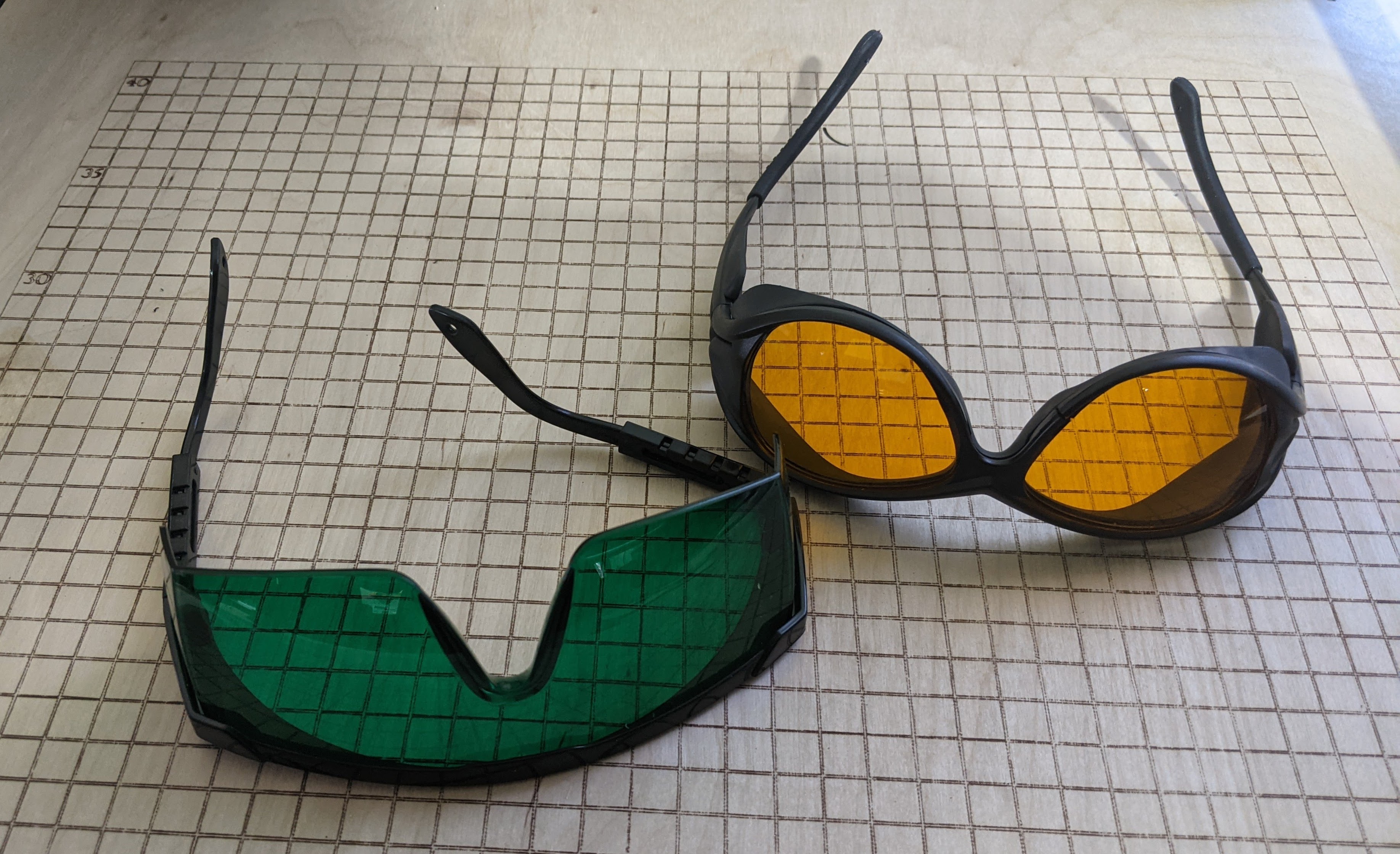
The glasses that come with the cutter seem to be adequate and some people have tested them by firing the laser through them. However, I opted for some better-quality glasses. Your eyes are worth more than a few bucks you can save with cheap glasses.

Be sure you have the latest firmware. My unit predated the January 2021 update and the fan did not run unless the laser was also running. I would guess this would shorten the laser diode’s life. With the updated firmware, there is smarter fan management along with some other fixes. The update is as simple as dragging and dropping a file, but for some reason, it only works under Windows. Linux sees the USB drive and will do the copy but it doesn’t stick. At least it didn’t brick the cutter.

Regardless of firmware, before you can cut, you’ll need to set the focus correctly. If you are like me, you are probably thinking: “Focus? You don’t focus a laser.” Well, turns out you do focus a cheap laser.

Focus is Everything

To get the required energy to the workpiece, the semiconductor laser passes through a lens that focuses the beam to — more or less — a point. That point is what does all the cutting or engraving. That means the piece you want to work with has to be at that focal point. After the lens, the beam will look like an hourglass and the further you are from the pinch in the hourglass, the less cutting you’ll do.

The Ortur’s laser doesn’t move up and down but the lens can either screw in and out a few millimeters or push in and out, depending on which one you have. Once you have something under the cutter, you can put some black construction paper over it and use that to visualize the focus. The software you are using will have a button to turn the laser on at low power. Using the glasses will help reduce the spillover and you’ll be able to see the main part of the beam easily on the black paper.

Some people use a USB microscope or other magnification to get the best focus. However, I didn’t like the stock method for focusing. The lens ring is hard to turn and even if you 3D print your own ring, it is awkward to spin the lens around. It also doesn’t afford you much range.

Luckily, there are many 3D printed solutions to create a moving laser head on the Ortur. I’ll show you the one I’m using next time. For now, assume you are going to focus the lens yourself. That limits the height of things you can cut or engrave, too, although some people put the machine on blocks to make more room underneath. A tight focus will let you cut or engrave quicker and make the cut line finer, too. However, even if you are a little off, you can usually get some result. It is a good idea to tape your work down or clamp it so if you need to you can do a second pass without moving anything.

There are different lenses you can get for the laser. The one the 15W machine comes with has a focal length of about 55 mm. However, there are other lenses — the G8 is popular — that have different focal lengths. Each lens has different characteristics as far as how tight they can focus and how many elements they have (more elements means less overall power).

The power delivered to your part is a combination of the beam power, the quality of the focus, and the time spent. Even the time it takes for the laser to change direction can cause a deeper burn or cut which is why most software offers an overscan function that keeps the laser off and away from the cut line when it changes direction.

If you are careful about focusing, you should be able to get a pretty good engraving on a piece of cardboard. Be sure to have something under it since you might cut through and leave a permanent mark. I mounted my cutter on a piece of plywood and I deliberately marked a grid on the board. I’ll tell you more about those additions next time.

Sometimes, you deliberately want to defocus a little to get wider lines. [Geordie_h] talks about this trick, along with some other pro tips that are aimed for a more commercial cutter, but still apply to the Ortur and other similar lasers.

Next Time

Speaking of next time, there’s a lot more to talk about. In addition to mounting the device and making the laser head move, I wanted to add air assist — something I’m still working on. This clear smoke from the cut as well as fine ash, allowing the laser to hit fresh material while cutting.

For some reason my machine will often stall on long cuts, and from reading the Internet, I’m not alone. Changing USB cables seemed to help. It may need a slightly beefier power supply or grounding on the frame. Then again, it could be power settings on my laptop. Time will tell. This has been particularly a problem when doing images that require a lot of time. You can see my picture of Rocky has a little misalignment at the top where I restarted after a failure like this and didn’t quite get it lined up right.

The Ortur reminds me of early 3D printers. It works, but it needs some work to get it to work well. But, for me at least, that’s the fun part anyway.

source https://hackaday.com/2021/02/23/hands-on-with-the-ortur-laser-cutter/

Lighted Raspberry Pico Stream Deck is Easy as Pi

Whether it’s for work, school, fun, or profit, nearly everyone is a content-creating video producer these days. And while OBS has made it easier to run the show, commanding OBS itself takes some hotkey finesse. Fortunately, it just keeps getting easier to build macro keyboards that make presenting a breeze. That includes the newest player to the microcontroller game — the Raspberry Pi Pico, which [pete_codes] used to whip up a nice looking OBS stream deck.

Sometimes you just need something that works without a lot of fuss — you can always save the fuss for version two. [pete_codes]’ Pico Producer takes advantage of all those I/O pins on the Pico and doesn’t use a matrix, though that is subject to change in the future. [pete_codes] likes the simplicity of this design and we do, too. You can see it in action after the break.

In reply to the Twitter thread, someone mentions re-legendable keycaps instead of the current 3D-printed-with-stickers keycaps, but laments the lack of them online. All we can offer is that re-legendable Cherry MX-compatible keycaps are definitely out there. Maybe not in white, but they’re out there.

If [pete_codes] wants to go wild in version two and make this macro keeb control much more than just OBS, he may want to leave the labeling to something dynamic, like an e-ink screen.

source https://hackaday.com/2021/02/23/lighted-raspberry-pico-stream-deck-is-easy-as-pi/

Lighted Raspberry Pico Stream Deck is Easy as Pi

Whether it’s for work, school, fun, or profit, nearly everyone is a content-creating video producer these days. And while OBS has made it easier to run the show, commanding OBS itself takes some hotkey finesse. Fortunately, it just keeps getting easier to build macro keyboards that make presenting a breeze. That includes the newest player to the microcontroller game — the Raspberry Pi Pico, which [pete_codes] used to whip up a nice looking OBS stream deck.

Sometimes you just need something that works without a lot of fuss — you can always save the fuss for version two. [pete_codes]’ Pico Producer takes advantage of all those I/O pins on the Pico and doesn’t use a matrix, though that is subject to change in the future. [pete_codes] likes the simplicity of this design and we do, too. You can see it in action after the break.

In reply to the Twitter thread, someone mentions re-legendable keycaps instead of the current 3D-printed-with-stickers keycaps, but laments the lack of them online. All we can offer is that re-legendable Cherry MX-compatible keycaps are definitely out there. Maybe not in white, but they’re out there.

If [pete_codes] wants to go wild in version two and make this macro keeb control much more than just OBS, he may want to leave the labeling to something dynamic, like an e-ink screen.

source https://hackaday.com/2021/02/23/lighted-raspberry-pico-stream-deck-is-easy-as-pi/

Lighted Raspberry Pico Stream Deck is Easy as Pi

Whether it’s for work, school, fun, or profit, nearly everyone is a content-creating video producer these days. And while OBS has made it easier to run the show, commanding OBS itself takes some hotkey finesse. Fortunately, it just keeps getting easier to build macro keyboards that make presenting a breeze. That includes the newest player to the microcontroller game — the Raspberry Pi Pico, which [pete_codes] used to whip up a nice looking OBS stream deck.

Sometimes you just need something that works without a lot of fuss — you can always save the fuss for version two. [pete_codes]’ Pico Producer takes advantage of all those I/O pins on the Pico and doesn’t use a matrix, though that is subject to change in the future. [pete_codes] likes the simplicity of this design and we do, too. You can see it in action after the break.

In reply to the Twitter thread, someone mentions re-legendable keycaps instead of the current 3D-printed-with-stickers keycaps, but laments the lack of them online. All we can offer is that re-legendable Cherry MX-compatible keycaps are definitely out there. Maybe not in white, but they’re out there.

If [pete_codes] wants to go wild in version two and make this macro keeb control much more than just OBS, he may want to leave the labeling to something dynamic, like an e-ink screen.

source https://hackaday.com/2021/02/23/lighted-raspberry-pico-stream-deck-is-easy-as-pi/

Pelton Turbine Development For An Air Powered Model Helicopter

[Tom Stanton] has been messing around with compressed air power for a few years now, and most of his work focused on piston engines. He likes using 2-liter soda bottles as lightweight tanks but their capacity is limited, so the nozzle can be a maximum of 1 mm in diameter if he wants to produce thrust for 30 seconds or longer using a turbine. Pelton turbines have been in use for a long time, especially for hydroelectric systems, and they use small diameter nozzles, so he decided to experiment with a pneumatic Pelton turbine. (Video, embedded below.)

Pelton wheels are water wheels with specially designed buckets to efficiently extract energy from a high-velocity jet of water. [Tom] 3D printed several geared Pelton turbines and started doing bench tests with a propeller and a load cell to gather empirical data. With the help of high-speed video of the tests, he quickly realized that the turbine efficiency is highly dependent on the load. If the load is too small or too large, the moving air will not come to a complete standstill, and energy will be wasted. [Tom] also suspected that some moving air was escaping from the bucket, so he created a version that enclosed the buckets with a ring on the outer perimeter, which increased the peak thrust output by 65%. Compared to his diaphragm air engine design, the peak thrust is higher, but the overall efficiency is less. [Tom] believes there is still room for improvement, so he plans to continue working on the Pelton turbine concept, with the hopes of building an air-powered model helicopter that can lift off.

One comment that came up a few times with his piston engine designs is whether venting the air straight out the nozzle, without a turbine or engine in the way, would be a better option. [Tom] tested this in the bench, and the straight-through nozzle was four times less efficient than the turbine. The reason for this was addressed in the comments on our article on diaphragm air engine and discussed on the Hackaday podcast. It’s an impedance matching problem, and an engine or turbine converts the small volume of high-velocity air into a large volume of low-velocity air.

source https://hackaday.com/2021/02/23/pelton-turbine-development-for-an-air-powered-model-helicopter/

LED Spectrum Visualizer Driven By Raspberry Pi

Back in the 1980s, spectrum displays on audio equipment were absolutely must have, and the aesthetic came to define the era. This lingered on through the 1990s, and remains a cool look even to this day. [Arduino Guy] decided to put together such a display using a Raspberry Pi and a large LED display.

The LED display in question is of the 64×64 RGB type, available from Aliexpress and other electronics suppliers online. To run the display, an Adafruit RGB Matrix Hat is used with the Raspberry Pi 3B, which makes driving the panel a cinch. The visual effect is run via a Python script, which plays a wave file and produces the spectrum graphics via a Fast Fourier Transform.

While the code isn’t able to act as a general-purpose equalizer display for any content played on the Raspberry Pi, creating such a script could be an entertaining exercise for the reader. Alternatively, the Pi could be hooked up to a microphone to run the display based on ambient room noise. In any case, we’ve seen great projects like this before, such as this laser-based display. Video after the break.

source https://hackaday.com/2021/02/22/led-spectrum-visualizer-driven-by-raspberry-pi/

3D Print a PCB the Hard Way

There’s an old joke about the physics student tasked with finding the height of a building using a barometer. She dropped the barometer from the roof and timed how long it took to hit the ground. Maybe that was a similar inspiration to [Moe_fpv_team’s] response to the challenge: use a 3D printer to create a PC board. The answer in that case? Print a CNC mill.

[Moe] had some leftover 3D printer parts. A $40 ER11 spindle gets control from the 3D printer software as a fan. The X, Y, and Z axis is pretty standard. The machine can’t mill metal, but it does handy on plywood and fiber board and should be sufficient to mill out a PCB from some copper clad board.

It would probably be possible to beef up the design by using rods larger than 8mm. Of course, you could just attach a spindle or even a rotary tool to a 3D printer, but the fact that the machine uses leadscrews on all axes should make it better at forcing its way through the material even if it is a little slower.

If you need a tutorial on how the process works, we’ve got you covered. If your setup isn’t robust enough to cut through copper, maybe you can just cut through the resist and etch.

source https://hackaday.com/2021/02/22/3d-print-a-pcb-the-hard-way/

How To Design a Custom Generator Interlock Plate

If you connect a generator to your home’s main electrical panel when the power goes out, you need to make sure the main breaker is shut off. Otherwise, when the power comes back on, you (or the linemen) are going to have a bad time. There are commercial interlock plates which physically prevent the generator and main breakers from being switched on at the same time, but since they tend to be expensive, [HowToLou] decided to make one himself.

The hardest part of this project is designing the template. It needs to be carefully shaped so its resting position prevents the generator’s breaker from being switched on under normal circumstances, but once the main is turned off and out of the way, you should be able to lift it up and have the clearance to flip the lower breaker. Spending some quality time at the breaker box with tape and a few pieces of cardboard is going to be the easiest way of finding the proper shape.

Making a template with thin cardboard.

In the video after the break, [HowToLou] demonstrates the ideal shape for his particular application, which should help you get your mind wrapped around the idea. There are a lot of variables involved, not least of which the size and placement of the breakers, so taking the time to get the template right is critical.

Once you have the shape, you could really make the plate however you want. [HowToLou] cuts his by hand out of a piece of thin aluminum, but you could certainly 3D print it or even CNC it out of a thicker piece of metal. The important thing is that its stiff enough that somebody can’t just bend it out of the way if they’re fumbling around with it in the dark.

It probably goes without saying that a homemade interlock isn’t going to be up to code, but even if you don’t have any inspectors sniffing around your electrical panel, it’s a sensible precaution to have something like this installed. The middle of winter is a bad time to realize you don’t have any way to safely power your home when the grid goes down, so the key is getting something like this ready to go before you actually need it.

source https://hackaday.com/2021/02/22/how-to-design-a-custom-generator-interlock-plate/

DIY Neuroscience Hack Chat

Join us on Wednesday, February 24 at noon Pacific for the DIY Neuroscience Hack Chat with Timothy Marzullo!

Watch a film about a mad scientist from the golden age of Hollywood and chances are good that among the other set pieces, you’ll see human brains floating in jars of cloudy fluid wired up to electrodes and fancy machines. It’s all made up, of course, but tropes work because they’re based on a kernel of truth, and we in the audience know that our brains and the other parts of our nervous system do indeed work on electricity. Or more precisely, excitable tissues in our nervous systems pass electrochemical signals between themselves as waves of potential across cell membranes.

Studying this electrical world locked away inside our heads is a challenging, but by no means impossible, pursuit. Usable signals can be picked up, amplified, digitized, and recorded to help us understand what’s going on when we think, feel, move, sleep, wake, or just be. Neuroscience has made tremendous strides looking at these signals, but the equipment to do so has largely remained the province of large universities and teaching hospitals with ample budgets, leaving the amateur neuroscientist out of luck.

Tim Marzullo, co-founder of Backyard Brains, is looking to change all that. While working on his Ph.D. in neuroscience at the University of Michigan, he and Greg Gage looked for ways to make the tools of neuroscience research affordable to everyone. The result is the Neuron SpikerBox, a low-cost bioamplifier that can tap into the “spikes” of action potential in live neurons. Open-source tools like these have helped educators bring neuroscience experiments to STEM students, and even helped other scientists set up novel, low-cost experiments.

Tim will join us on the Hack Chat to talk about doing DIY neuroscience and designing the instruments that make it possible. Bring your “mad scientist” questions as we push back the veil of ignorance on how our brains work, one neuron at a time.

join-hack-chatOur Hack Chats are live community events in the Hackaday.io Hack Chat group messaging. This week we’ll be sitting down on Wednesday, February 24 at 12:00 PM Pacific time (UTC-8). If time zones have you tied up, we have a handy time zone converter.

Click that speech bubble to the right, and you’ll be taken directly to the Hack Chat group on Hackaday.io. You don’t have to wait until Wednesday; join whenever you want and you can see what the community is talking about.


source https://hackaday.com/2021/02/22/diy-neuroscience-hack-chat/