All The Good VR Ideas Were Dreamt Up In The 60s

Virtual reality has seen enormous progress in the past few years. Given its recent surges in development, it may come as a bit of a surprise to learn that the ideas underpinning what we now call VR were laid way back in the 60s. Not all of the imagined possibilities have come to pass, but we’ve learned plenty about what is (and isn’t) important for a compelling VR experience, and gained insights as to what might happen next.

If virtual reality’s best ideas came from the 60s, what were they, and how did they turn out?

Interaction and Simulation

First, I want to briefly cover two important precursors to what we think of as VR: interaction and simulation. Prior to the 1960s, state of the art examples for both were the Link Trainer and Sensorama.

The Link Trainer was an early kind of flight simulator, and its goal was to deliver realistic instrumentation and force feedback on aircraft flight controls. This allowed a student to safely gain an understanding of different flying conditions, despite not actually experiencing them. The Link Trainer did not simulate any other part of the flying experience, but its success showed how feedback and interactivity — even if artificial and limited in nature — could allow a person to gain a “feel” for forces that were not actually present.

Sensorama was a specialized pod that played short films in stereoscopic 3D while synchronized to fans, odor emitters, a motorized chair, and stereo sound. It was a serious effort at engaging a user’s senses in a way intended to simulate an environment. But being a pre-recorded experience, it was passive in nature, with no interactive elements.

Combining interaction with simulation effectively had to wait until the 60s, when the digital revolution and computers provided the right tools.

The Ultimate Display

In 1965 Ivan Sutherland, a computer scientist, authored an essay entitled The Ultimate Display (PDF) in which he laid out ideas far beyond what was possible with the technology of the time. One might expect The Ultimate Display to be a long document. It is not. It is barely two pages, and most of the first page is musings on burgeoning interactive computer input methods of the 60s.

The second part is where it gets interesting, as Sutherland shares the future he sees for computer-controlled output devices and describes an ideal “kinesthetic display” that served as many senses as possible. Sutherland saw the potential for computers to simulate ideas and output not just visual information, but to produce meaningful sound and touch output as well, all while accepting and incorporating a user’s input in a self-modifying feedback loop. This was forward-thinking stuff; recall that when this document was written, computers weren’t even generating meaningful sounds of any real complexity, let alone visual displays capable of arbitrary content.

A Way To Experience The Unreal
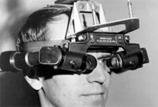
Closeup of Sutherland’s Sword of Damocles, a ceiling-suspended system into which a user’s head was strapped. [image source: History of VR]

Sutherland’s main idea was this: as humans, we have an intuitive familiarity with what we can see and feel. The effects of gravity, how it feels to start or stop something from moving, or imagining how an object will look from a different angle, these are all things we comprehend effortlessly.

What if we could similarly experience concepts that could not be realized in our physical world? It would be a way to gain intuitive and intimate familiarity with concepts not otherwise available to us.

As a first step in actualizing these ideas, Sutherland and some of his students created a large ceiling-suspended system dubbed Sword of Damocles. It was the first head-mounted display whose visuals did not come from a camera, but were generated by a computer. It displayed only line-based vector graphics, but it was able to modify what it showed in real-time based on head position and user input.

Leveraging a computer’s ability to process feedback and dynamically generate visuals was key to an interactive system capable of generating its own simulated environment. For the first time, a way to meaningfully fuse interaction with abstract simulation was within reach, and there was nowhere to go but up.

Ideas From the 60s That Happened

Many concepts that Sutherland predicted have come to pass, at least partially, and are recognizable in some modern form.

Objects Displayed by a Computer Need Not Follow Ordinary Rules of Reality

Being able to define things free from the confines of physical reality, and adjust their properties at will, encompasses functions like CAD modeling and other simulation work as well as it does entertainment like gaming. In fact, it would even be fair to say that gaming in particular thrives in this space.

Sutherland envisioned a computer-controlled display as a looking glass into a mathematical wonderland. A great example of this concept is this 3D engine for non-Euclidean geometry which presents impossible geometries in a familiar, interactive way.

Tactile and Haptic Feedback

Today’s VR controllers (and mobile devices like phones, for that matter) rely heavily on being able to deliver a range of subtle vibrations as meaningful feedback. While not measuring up to Sutherland’s ideal of accurately simulating things like complex physics, it nevertheless gives users an intuitive understanding of unseen forces and boundaries, albeit simple ones, like buttons that do not exist as physical objects.

Head Tracking

Making a display change depending on where one is looking is a major feature of VR. While Sutherland only mentioned this concept briefly, accurate and low-latency tracking has turned out to be a feature of critical importance. When Valve was first investigating VR and AR, an early indicator that they were onto something was when researchers experienced what was possible when low-persistence displays were combined with high-quality tracking; it was described as looking through a window into another world.

Hand and Body Tracking, Including Gaze Tracking

Sutherland envisioned the ability of a computer to read a user’s body as an input method, particularly high-dexterity parts of the body like the hand and eyes. Hand tracking is an increasingly common feature in consumer VR systems today. Eye tracking exists, but more on that in a moment.

Some Ideas Haven’t Happened Yet

There are a number of concepts that haven’t happened, or exist only in a very limited way, but that list is shrinking. Here are the most notable standouts.

Robust Eye Tracking Is Hard

Sutherland wrote “it remains to be seen if we can use a language of glances to control a computer,” and so far that remains the case.

It turns out that eye tracking is fairly easy to get mostly right: one simply points a camera at an IR-illuminated eyeball, looks for the black circle of the pupil, and measures its position to determine where its owner is looking. No problems there, and enterprising hackers have made plenty of clever eye tracking projects.

Eye tracking gets trickier when high levels of reliable accuracy are needed, such as using it to change how visuals are rendered based on exactly where a user is looking. There are a number of reasons for this: not only does the human eye make frequent, involuntarily movements called saccades, but roughly 1% of humans have pupils that do not present as nice round black shapes, making it difficult for software to pick out. On top of that, there is a deeper problem. Because a pupil is nothing more than an opening in the flexible tissue of the iris, it is not always a consistent shape. The pupil in fact wobbles and wiggles whenever the eye moves — which is frequently — and this makes highly accurate positioning difficult to interpret. Here is a link (cued to 37:55 in) to a video presentation explaining these issues, showing why it is desirable to avoid eye tracking in certain applications.

Simulation-Accurate Force Feedback Isn’t Ready

Force feedback devices have existed for years, and there is renewed interest in force feedback thanks to VR development. But we are far from using it in the way Sutherland envisioned: to simulate and gain intuitive familiarity with complex concepts and phenomena, learning them as well as we know our own natural world.

Simulating something like a handshake or a hug ought to be simple by that metric, but force feedback that can meaningfully simulate simple physics remains the realm of expensive niche applications that can’t exist without specialized hardware.

Holodeck-level Simulation

Probably the most frequently-quoted part of The Ultimate Display is the final few sentences, in which Sutherland describes something that sounds remarkably like the holodeck from Star Trek:

The ultimate display would, of course, be a room within which the computer can control the existence of matter. A chair displayed in such a room would be good enough to sit in. Handcuffs displayed in such a room would be confining, and a bullet displayed in such a room would be fatal. With appropriate programming such a display could literally be the Wonderland into which Alice walked.

Clearly we’re nowhere near that point, but if we ever are, it might be the last thing we ever need to invent.

Important Features vs. Cool Ones

The best ideas may have come from the 60s, but we’ve learned a lot since then about what is and isn’t actually important to creating immersive experiences. Important features are the ones a technology really needs to deliver on, because they are crucial to immersion. Immersion is a kind of critical mass, a sensory “aha!” moment in which one ceases to notice the individual worky bits involved, and begins to interact seamlessly and intuitively with the content in a state of flow. Important features help that happen.

For example, it may seem that a wide field of view in an HMD is important for immersion, but that turns out to not quite be the case. We covered a fascinating presentation about how human vision uses all sorts of cues to decide how “real” something is, and what that means for HMD development. It turns out that a very wide field of view in a display is desirable, but it is not especially important for increasing immersion. Audio has similar issues, with all kinds of things being discovered as important to delivering convincing audio simulation. For example, piping sound directly into the ear canals via ear buds turns out to be a powerful way for one’s brain to classify sounds as “not real” no matter how accurately they have been simulated. Great for listening to music, less so for a convincing simulation.

Another feature of critical importance is a display with robust tracking and low latency. I experienced this for myself the first time I tried flawless motion tracking on a modern VR headset. No matter how I moved or looked around, there was no perceptible lag or drift. I could almost feel my brain effortlessly slide into a groove, as though it had decided the space I was in and the things I was looking at existed entirely separate from the thing I was wearing on my head. That was something I definitely did not feel when I wore a Forte VFX1 VR headset in the mid-90s. At the time, it wasn’t the low resolution or the small field of view that bothered me, it was the drifty and vague head tracking that I remember the most. There was potential, but it’s no wonder VR didn’t bloom in the 90s.

What’s Next?

One thing that fits Sutherland’s general predictions about body tracking, but which he probably did not see coming, is face and expression tracking. It is experimental work from Facebook, but is gaining importance mainly for the purpose of interacting with other people digitally, rather than as a means of computer input.

Speaking of Facebook, a social network spearheading VR development (while tightening their grip on it) definitely was not predicted in the 60s, yet it seems to be next for VR nevertheless. But I never said the future of VR came from the 60s, just that the good ideas did.

source https://hackaday.com/2021/01/04/all-the-good-vr-ideas-were-dreamt-up-in-the-60s/
Tighten This Bolt in Any Direction You Want

Metal lathes are capable machines that played a large role in the industrial revolution, and an incredible tool to have at your disposal. But that doesn’t mean they can’t be used to have a little fun, as demonstrated by [Oleg Pevtsov] who made a bidirectional bolt as a machining exercise just because he could.

Both videos after the break are in Russian, but the video and auto generated subtitles are enough to get the main points across. The bolt is an M42 size with a 40 mm pitch, with grooves cut in both directions to allow left-handed and right-handed nuts to be threaded. The large pitch means that instead of a single continuous groove like a normal bolt, ten separate grooves need to be cut for each threading direction to cover the bolt surface. Since this was all machined on a manual lathe, a dial indicator was required to maintain accurate spacing. It took [Oleg] four painstaking attempts to get it right, but the end result looks very good. Instead of a fixed cutter, he used a trimming router mounted on a custom clamp.

[Oleg] also machined three different brass nuts to go on the bolt with a fixed cutter. First left-hand and right hand threaded nuts were made, followed by a bidirectional nut. Due to the large pitch and careful machining, all three nuts will spin down the bolt under the force of gravity alone. Although the bidirectional nut doesn’t move as smoothly as the other two, it can change rotation and translation direction at random.

While this is a one-of-a-kind fidget toy, have any of our readers seen a bidirectional bolt or lead screw in the wild? We can imagine that the ability to move two nuts in opposite directions on a single lead screw might have some practical applications.

It’s possible to make incredible parts on a manual lathe. A handbuilt V10 engine and a pneumatic hexacopter model are just two examples of what’s possible with enough skill, knowledge, and patience. Sadly it is a fading form of craftsmanship, rendered mostly obsolete outside of hobby projects by CNC machines.

source https://hackaday.com/2021/01/04/tighten-this-bolt-in-any-direction-you-want/

Never Forget To Turn On The Cooker Hood Again

The cooker hood is a wonderful invention for removing excess fumes and steam from the kitchen. But like all electrically-powered devices, it only works when it is turned on. This was the problem facing [Peter], whose family are enthusiastic cooks who frequently forget to hit that switch. His solution? An automatic cooker hood switch that comes on when the cooker is in use, and stays on long enough afterwards to fully dissipate the fumes.

At its heart is a current transformer on the 3-phase stove power line, and we’re treated to a lesson in reading from these devices with an Arduino. They have a shunt resistor across which to produce a voltage, and their AC output is placed upon a reference DC voltage to supply the microcontroller pin. The impedance is quite high, so when the sensor had to be placed a distance from the microcontroller it necessitated an op-amp buffer. The readings then cause the Arduino to trigger a pair of relays to switch on or off the cooker hood. We can imagine that the family kitchen is thus a much pleasanter environment for it.

Cookers can also provide quite a hazard when they are left on. To that end, we’ve also featured a cooker alarm in the past.

Header image: Pbroks13, CC BY-SA 3.0.

source https://hackaday.com/2021/01/04/never-forget-to-turn-on-the-cooker-hood-again/

ABS Mercedes Rims Push The Limits Of 3D Printing

While we’re big believers in 3D printing here at Hackaday, there’s no denying that some things just aren’t meant to be printed. For example, most of us would agree that it’s not the first choice for making rims for a passenger car. We imagine that [Jón Schone] from Proper Printing probably feels the same way, but that didn’t stop him from trying to do it anyway.

A couple of months ago [Jón] got a test subject in the form of an older Mercedes with 19-inch rims. The first two challenges are bed size and warping, so he modified a Creality CR10 S5 with a heated chamber capable of reaching 70 °C to reduce warping with the ABS filament he intended to use. Another challenge is the amount of filament required for the print, especially since [Jón] wasn’t keen on babysitting the machine to replace the spool every so often. His attempt at building a filament joiner ultimately didn’t work out, so in the end he simply sourced the filament in bulk size rolls.

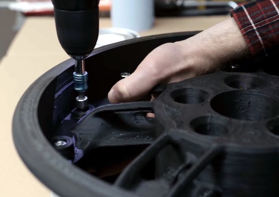
Bolts hold the two halves of the rim together.

Eventually [Jón] managed to print a complete rim in two halves, bolted together around its circumference. Unfortunately, even with the heated chamber, the parts still warped all around the edges. This left a gap at the seam, but to fit a tubeless tire, the rim had to be airtight. So the entire inside surface was painted to close any small gaps, and the larger gaps were filled with sealant.

In the end it was still unable to hold pressure with a tire mounted, so it was test fitted to the car just to see if it would carry the weight. This test also failed, splitting on the thinnest part of the rim. [Jón] has headed back to the drawing board to try again in 2021. We probably would have moved on by now, but you have to admire his tenacity. We hope to see success in the new year.

Printing large parts brings its own set of challenges, but if you stick to good old PLA it’s not too difficult. [Ivan Miranda] has made a name for himself with massive 3D printed projects like a ride-able tank, and also built a supersized 3D printer for future projects.

source https://hackaday.com/2021/01/03/abs-mercedes-rims-push-the-limits-of-3d-printing/

Uncommon Bárány Chair Gets Fixed Up

Ever heard of a Bárány chair? Neither had [Troy Denton] before he was asked to repair one, but that didn’t stop him from rolling up his sleeves and tying to get the non-functional device back in working order. As it didn’t come with a user guide, manual, schematic or any other information, he had to rely on his experience and acumen gathered over years of practical work. Luckily for us, he decided to document the whole process.

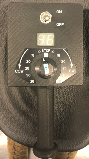
While it’s not well known outside of aviation circles, the Bárány chair is an important piece of equipment in training pilots to get used to spatial disorientation. The device is essentially a motorized revolving chair, the idea being to spin the subject to induce disorientation. Rotation speed and direction can be controlled via a handheld wireless remote terminal.

When [Troy] first powered it up, the error code on the remote indicated “no power to base unit”. That turned out to be a quick fix – he simply had to move the power connection from a switched socket that had been turned off to a different outlet. But while that cleared the error message, the chair still wouldn’t rotate for any of the knob settings.

Manually rotating the chair showed the RPM on the remote, so [Troy] narrowed down his search to the motor related sections. The motor was being driven by a servo type signal, but changing the speed and direction knob on the remote didn’t seem to alter the control signal when he checked it with his scope. Opening up the hand held remote immediately uncovered the failed part – the rotary encoder for setting the speed and direction had physically split in to two pieces.

Since there was a clean split in the encoder, he was able to temporarily hold it back together to confirm that the chair could spin up. The cause was most likely “User Error” – the last person to conduct the test probably turned the knob rather enthusiastically. A new part is on the way, and the chair should be getting back to making prospective pilots dizzy in no time.

We love a good repair story here at Hackaday. Whether it’s patiently rebuilding a snapped PCB with bodge wires or coming up with replacement parts that may well be better than the originals, we never get tired of seeing a broken piece of gear put back together.

Thanks to [Tim Gremalm] for the tip.

source https://hackaday.com/2021/01/03/uncommon-barany-chair-gets-fixed-up/

Uncommon Bárány Chair Gets Fixed Up

Ever heard of a Bárány chair? Neither had [Troy Denton] before he was asked to repair one, but that didn’t stop him from rolling up his sleeves and tying to get the non-functional device back in working order. As it didn’t come with a user guide, manual, schematic or any other information, he had to rely on his experience and acumen gathered over years of practical work. Luckily for us, he decided to document the whole process.

While it’s not well known outside of aviation circles, the Bárány chair is an important piece of equipment in training pilots to get used to spatial disorientation. The device is essentially a motorized revolving chair, the idea being to spin the subject to induce disorientation. Rotation speed and direction can be controlled via a handheld wireless remote terminal.

When [Troy] first powered it up, the error code on the remote indicated “no power to base unit”. That turned out to be a quick fix – he simply had to move the power connection from a switched socket that had been turned off to a different outlet. But while that cleared the error message, the chair still wouldn’t rotate for any of the knob settings.

Manually rotating the chair showed the RPM on the remote, so [Troy] narrowed down his search to the motor related sections. The motor was being driven by a servo type signal, but changing the speed and direction knob on the remote didn’t seem to alter the control signal when he checked it with his scope. Opening up the hand held remote immediately uncovered the failed part – the rotary encoder for setting the speed and direction had physically split in to two pieces.

Since there was a clean split in the encoder, he was able to temporarily hold it back together to confirm that the chair could spin up. The cause was most likely “User Error” – the last person to conduct the test probably turned the knob rather enthusiastically. A new part is on the way, and the chair should be getting back to making prospective pilots dizzy in no time.

We love a good repair story here at Hackaday. Whether it’s patiently rebuilding a snapped PCB with bodge wires or coming up with replacement parts that may well be better than the originals, we never get tired of seeing a broken piece of gear put back together.

Thanks to [Tim Gremalm] for the tip.

source https://hackaday.com/2021/01/03/uncommon-barany-chair-gets-fixed-up/

Hackaday Links: January 3, 2021

Last week we featured a story on the new rules regarding drone identification going into effect in the US. If you missed the article, the short story is that almost all unmanned aircraft will soon need to transmit their position, altitude, speed, and serial number, as well as the position of its operator, likely via WiFi or Bluetooth. The FAA’s rule change isn’t sitting well with Wing, the drone-based delivery subsidiary of megacorporation Alphabet. In their view, local broadcast of flight particulars would be an invasion of privacy, since observers snooping in on Remote ID traffic could, say, infer that a drone going between a pharmacy and a neighbor’s home might mean that someone is sick. They have a point, but how a Google company managed to cut through the thick clouds of irony to complain about privacy concerns and the rise of the surveillance state is mind boggling.

Speaking of regulatory burdens, it appears that getting an amateur radio license is no longer quite the deal that it once was. The Federal Communications Commission has adopted a $35 fee for new amateur radio licenses, license renewals, and changes to existing licenses, like vanity call signs. While $35 isn’t cheap, it’s not the end of the world, and it’s better than the $50 fee that the FCC was originally proposing. Still, it seems a bit steep for something that’s largely automated. In any case, it looks like we’re still good to go with our “$50 Ham” series.

Staying on the topic of amateur radio for a minute, it looks like there will be a new digital mode to explore soon. The change will come when version 2.4.0 of WSJT-X, the program that forms the heart of digital modes like WSPR and FT8, is released. The newcomer is called Q65, and it’s basically a follow-on to the current QRA64 weak-signal mode. Q65 is optimized for weak, rapidly fading signals in the VHF bands and higher, so it’s likely to prove popular with Earth-Moon-Earth fans and those who like to do things like bounce their signals off of meteor trails. We’d think Q65 should enable airliner-bounce too. We’ll be keen to give it a try whenever it comes out.

Look, we know it’s hard to get used to writing the correct year once a new one rolls around, and that time has taken on a relative feeling in these pandemic times. But we’re pretty sure it isn’t April yet, which is the most reasonable explanation for an ad purporting the unholy coupling of a gaming PC and mass-market fried foods. We strongly suspect this is just a marketing stunt between Cooler Master and Yum! Brands, but taken at face value, the KFConsole — it’s not a gaming console, it’s at best a pre-built gaming PC — is supposed to use excess heat to keep your DoorDashed order of KFC warm while you play. In a year full of incredibly stupid things, this one is clearly in the top five.

And finally, it looks like we can all breathe a sigh of relief that our airline pilots, or at least a subset of them, aren’t seeing things. There has been a steady stream of reports from pilots flying in and out of Los Angeles lately of a person in a jetpack buzzing around. Well, someone finally captured video of the daredevil, and even though it’s shaky and unclear — as are seemingly all videos of cryptids — it sure seems to be a human-sized biped flying around in a standing position. The video description says this was shot by a flight instructor at 3,000 feet (914 meters) near Palos Verdes with Catalina Island in the background. That’s about 20 miles (32 km) from the mainland, so whatever this person is flying has amazing range. And, the pilot has incredible faith in the equipment — that’s a long way to fall in something with the same glide ratio as a brick.

source https://hackaday.com/2021/01/03/hackaday-links-january-3-2021/

Active Aero For A Radio Control Car

Motorsport became obsessed with aerodynamics in the middle of the 20th century. Moving on from simple streamlined shapes, designers aimed to generate downforce with wing elements in order to get more grip between the tyres and the track. This culminated in the development of active aero, where wing elements are controlled by actuators to adjust the downforce as needed for maximum grip and minimum drag. Recently, [Engineering After Hours] decided to implement the technology on his Traxxas RC car.

The system consists of a simple multi-element front wing, chosen for its good trade-off between downforce and drag. The wing is mounted to a servo, which varies the angle of attack as the car’s pitch changes, as detected by a gyroscope. As the car pitches up during acceleration, the angle of the wing is increased to generate more downforce, keeping the nose planted.

The basic concept is sound, though as always, significant issues present themselves in the implementation. Small bumps cause the system to over-react, folding the wing under the front wheels. Additionally, the greater front downforce caused over-steer, leading to the install of a rear wing as well for better aero balance.

Regardless of some hurdles along the way, it’s clear the system has potential. We look forward to the next build from [Engineering After Hours], which promises to mimic the fan cars of the 70s and 80s. If you’re looking to improve aero on your full-size car, we’ve got a guide to that too. Video after the break.

[Thanks to Zane Atkins for the tip!]

source https://hackaday.com/2021/01/03/active-aero-for-a-radio-control-car/

Dog Bowls Show the Versatility of Ceramic Slip Casting

Here at Hackaday, we feature projects that are built of just about every material imaginable. Silicon-spangled fiber-reinforced epoxy resin is our primary medium, but we see plastic, wood, steel, aluminum, and even textiles from time to time. It’s not often we see slip-cast ceramic molding, though, and when it pops up, it’s always good to take a look at this versatile manufacturing method.

The back-story on this one is that [thoughtfulocean], a mechanical engineer idled by COVID lockdowns, wanted custom water bowls for his dogs, one of whom is clearly a grumpy Ewok. The design started with a 3D-print of the final vessel, printed in sections and glued together. These were used to create a two-piece plaster mold into which a watery slurry of clay, or slip, was poured. The plaster mold dehydrates the slip, leaving behind a semi-solid layer of clay of the desired thickness once the excess slip is poured off. The resulting casting is then fired in a kiln and glazed.

Of course, [thoughtfulocean] ran into a few problems along the way. The first mold was warped thanks to the mold box bowing under pressure from the plaster, so the whole molding process had to be revamped. The finished bowl also shrunk less than expected after firing, which led to some more revisions. But the finished bowl look really nice, and the included pump and filter keeps the Ewok’s water free from the yuck a dog’s face can introduce. As a bonus, it sounds like [thoughtfulocean] might have created a marketable product from all this. Take that, COVID!

Slip-casting ceramic may not be all that common around here, but ceramic as a material isn’t exactly a stranger. And who says slip casting is limited to ceramic? After all, we’ve seen a similar method used with plastic resin.

[via r/engineering]

source https://hackaday.com/2021/01/03/dog-bowls-show-the-versatility-of-ceramic-slip-casting/

An Arduino And A CD-ROM Drive Makes A CD Player

In an age of streaming media it’s easy to forget the audio CD, but they still remain as a physical format from the days when the “Play” button was not yet the “Pay” button. A CD player may no longer be the prized possession it once was, but it’s still possible to dabble in the world of 120 mm polycarbonate discs if you have a fancy for it. It’s something [Daniel1111] has done with his Arduino CD player, which uses the little microcontroller board to control a CD-ROM drive via its IDE bus.

The project draws heavily from the work of previous experimenters, notably ATAPIDUINO, but it extends them by taking its audio from the drive’s S/PDIF output. A port expander drives the IDE interface, while a Cirrus Logic WM8805 S/PDIF transceiver handles the digital audio and converts it to an I2S stream. That in turn is fed to a Texas Instruments PCM5102 DAC, which provides a line-level audio output. All the code and schematic can be found in a GitHub repository.

To anyone who worked in the CD-ROM business back in the 1990s this project presses quite a few buttons, though perhaps not enough to dig out all those CDs again. It would be interesting to see whether the I2S stream could be lifted from inside the drive directly, or even if the audio data could be received via the IDE bus. If you’d like to know a bit more about I2S , we have an article for you.

source https://hackaday.com/2021/01/03/an-arduino-and-a-cd-rom-drive-makes-a-cd-player/

Blackboard Becomes Tidy Pen Plotter

Printers are all well and good, but they’re generally limited to smaller paper sizes and use expensive ink. If you instead want to produce art on a larger scale, a plotter can be a great way to go. [tuenhidiy] built a tidy example using an old blackboard as a base.

These days, such a build is quite easily approachable, thanks to the broad DIY CNC and 3D printing communities. The plotter consists of a pair of stepper motors, driven by an off-the-shelf RAMPS 1.4 controller and an Arduino Mega 2560. The motors are mounted at the top corners of the blackboard, and move the pen holder via a pair of toothed belts, counter-weighted for stability. The pen holder itself mounts a simple permanent marker, and uses a servo to push the holder away from the paper for retraction, rather than moving the pen itself. Control of the system is via the Makelangelo firmware, an open-source effort capable of driving a wide variety of CNC motion systems.

The final result is a simple plotter using readily available parts that can reliably plot large graphics on a piece of A1 paper. We’re particularly impressed by the clean, continuous lines it produces – testament to a sound mechanical design.

We see plenty of plotters around these parts; even rotary types that can draw on curves. Video after the break.

source https://hackaday.com/2021/01/03/blackboard-becomes-tidy-pen-plotter/

Listening To Long Forgotten Voices: An Optical Audio Decoder For 16 mm Film

Like many of us, [Emily] found herself on COVID-19 lockdown over the summer. To make the most of her time in isolation, she put together an optical audio decoder for old 16 mm film, built using modern components and a bit of 3D printing.

It all started with a broken 16 mm projector that [Emily] got from a friend. After repairing and testing the projector with a roll of film bought at a flea market, she discovered that the film contained an audio track that her projector couldn’t play. The audio track is encoded as a translucent strip with varying width, and when a mask with a narrow slit is placed over the top it modulates the amount of light that can pass through to a light sensor connected to speakers via an amplifier.

[Emily] used a pair of razor blades mounted to a 3D printed bracket to create the mask, and a TI OPT101 light sensor together with a light source to decode the optical signal. She tried to use a photoresistor and a discrete photodiode, but neither had the required sensitivity. She built a frame with adjustable positions for an idler pulley and the optical reader unit, an electronics box on one end for the electronic components, and another pulley attached to a stepper motor to cycle a short loop of the film.

Most of the projects we see involving film these days are for creating digital copies. You can digitize your old 35 mm photo film using a Raspberry Pi, some Lego pieces, and a DSLR camera, or do the same for 8 mm film with a 3D printed rig.

source https://hackaday.com/2021/01/02/listening-to-long-forgotten-voices-an-optical-audio-decoder-for-16-mm-film/

Checking in on Low-Cost CNC Machines

Low cost 3D printers have come a long way in the last few years, but have entry-level CNC machines improved by the same leaps and bounds? That’s what [ModBot] recently set out to find. Despite getting burned pretty badly on a cheap CNC a few years back, he decided to try again with a sub $400 machine from FoxAlien. You can see his full review after the break.

The machine looks very similar to other generic CNC machines you see under many brand names, sometimes for a good bit less. The 3018 number is a giveaway that the work area is 30×18 cm and a quick search pulled up several similar machines for just a bit more than $200. The FoxAlien did have a few nice features, though. It has a good-looking build guide and an acrylic box to keep down the shaving debris in your shop. There are also some other nice touches like a Z-axis probe and end stops. If you add those items to the cut-rate 3018 machines, the FoxAlien machine is pretty price competitive when you buy it from the vendor’s website. The Amazon page in the video shows $350 which is a bit more expensive but does include shipping.

As with most of these cheap CNC machines, one could argue that it’s more of an engraver than a full mill. But on the plug side, you can mount other tools and spindles to get different results. You can even turn one of these into a diode laser cutter, but you might be better off with something purpose-built unless you think you’ll want to switch back and forth often.

This reminded us of a CNC we’ve used a lot, the LinkSprite. It does fine for about the same price but we are jealous of the enclosure. Of course, half the fun of owning something like this is hacking it and there are plenty of upgrades for these cheap machines.

source https://hackaday.com/2021/01/02/checking-in-on-low-cost-cnc-machines/

Mattress-made MIDI Device Plays Exotic Tunes

Ever heard of a handpan? If not, imagine a steel drum turned inside out, and in case that doesn’t help either, just think of a big metal pan you play music with by tapping your hands on its differently pitched tone fields. But as with pretty much any musical instrument, the people around you may not appreciate your enthusiasm to practice playing it at any time of the day, and being an acoustic instrument, it gets difficult to just plug in your headphones. Good news for the aspiring practitioners of Caribbean music though, as [Deepsoul77] created a MIDI version of this rather young and exotic instrument.

Using the foam salvaged from an old mattress as the core of the handpan, [Deepsoul77] cut a couple of plywood pads as tone fields that will be attached to the foam. Each plywood tone field will then have a piezo element mounted in between to pick up the hand tapping. Picking up the tapping itself and turning it into MIDI signals is then handled by an Alesis trigger interface, which is something you would usually find in electronic drums. From here on forward, it all becomes just a simple USB MIDI device, with all the perks that brings along — like headphone usage or changing MIDI instruments to make anything sound like a trumpet.

Turning what’s essentially a drum kit into a melodic instrument is definitely neat, and to no surprise, we’ve also seen the actual home made drum kit with piezo elements. Of course, using MIDI to quiet down an acoustic instrument isn’t new either, though it also works somewhat the other way around. But then again, it doesn’t always have to be MIDI either.

source https://hackaday.com/2021/01/02/mattress-made-midi-device-plays-exotic-tunes/

A Vintage Flip Clock Gets Some Modern Love

There are multiple reasons why we like [iSax]’s rebuild of a Bodet flip clock from the early 1980s. First there’s the retro charm of the timepiece itself, then the electronics used to drive it, its electromechanical month length and leap year system, and finally because here is a maker lucky enough to have a beautiful tabby cat to share the workbench with.

For those of you unfamiliar with a flip clock, these devices have their digits as a series of hinged cards on a central rotor, with each one being exposed in turn as the rotor turns. This one is part of a distributed clock system in which the clients receive a 1 Hz pulse from a central time server to drive their motors, something easily replicated with an Arduino and an H-bridge. Particularly fascinating though is the month length mechanism, part of the calendar rotor system, it has a small DC motor that is engaged to advance the days automatically by whichever number as part of the month transition. Originally this was powered by a couple of AA batteries, which have now been replaced with a small DC to DC converter. You can see it in action in the video below the break.

With or without tabby cats, we see quite a few projects featuring them. If you can’t find one, you can always make your own.

source https://hackaday.com/2021/01/02/a-vintage-flip-clock-gets-some-modern-love/

Build an 8-bit CPU to Know “But How Do It Know?”

Sometime around 2009, [J. Clark Scott] published a book aimed to demystify computers for everyone by walking through construction of an 8-bit CPU from scratch. The book had a catchy, but somewhat confusing title But How Do It Know?. The back story on the title goes something like this: Joe is a very nice fellow, but has always been a little slow. He goes into a store where a salesman is standing on a soapbox in front of a group of people. The salesman is pitching the miracle new invention, the Thermos bottle. He is saying, “It keeps hot food hot, and cold food cold….” Joe thinks about this a minute, amazed by this new invention that is able to make a decision about which of two different things it is supposed to do depending on what kind of food you put in it. He can’t contain his curiosity, he is jumping up and down, waving his arm in the air, saying “but, but, but, but…” Finally he blurts out his burning question “But how do it know?” Joe looked at what this Thermos bottle could do, and decided that it must be capable of sensing something about its contents, and then performing a heating or cooling operation accordingly. Joe’s concept of how the bottle worked was far more complicated than the truth. With that introductory opening, [J. Clark Scott] goes on to cover basic number theory, leading on to logic gates, and finally the 8-bit CPU.

[Patrick LeBoutillier] decided to build a hardware version of the CPU/computer as described in [John Clark Scott]’s book. In order to keep size and cost within reasonable bounds, he choose a hybrid construction using a combination of micro-controllers and SN74HC logic IC’s. When used as a companion project alongside reading the book, he hopes people can get their hands dirty and try it out for themselves. He has published a series of 14 videos covering construction of the CPU and the first Introductory video is embedded after the break below. For the micro-controller part of the project, he is using four Arduino Nanos, the code and install instructions for which are available at his Git repo. The Fritzing schematic, also available at the repo, might look a bit daunting at first look, but when you follow along his video series, it becomes easier. You can preview the first three chapters of the book at the “But How Do It Know?” website.

If FPGA’s are more of a thing for you, or you’d like to dip your feet learning FPGA, then [Patrick] has another series of 17 videos (embedded below) where he goes through the same process using a Digilent BASYS3 FPGA development board. These aren’t your only options — if you just want to understand how it works, without having to build the hardware, then check out the online, browser based implementation of the [Clark Scott] CPU.

If it seems the breadboard build of this 8-bit CPU looks complex, then this
Home Made 8-bit CPU Is A Wiry Blinky Build and a veritable rats nest of jumper wires.

source https://hackaday.com/2021/01/02/build-an-8-bit-cpu-to-know-but-how-do-it-know/

How A Quadriplegic Patient Was Able To Eat By Himself Again Using Artificial Limbs

Thirty years ago, [Robert “Buz” Chmielewski] suffered a surfing accident as a teenager. This left him as a quadriplegic due to a C6 spinal cord injury. After becoming a participant in a brain-computer interface study at Johns Hopkins, he was recently able to feed himself through the use of prosthetic arms. The most remarkable thing about these prosthetic arms is primarily the neural link with [Buz’s] brain, which allows him to not only control the artificial arms, but also feel what they are touching, due to a closed-loop system which transfers limb sensory input to the patient’s brain.

The prosthetic limb in question is the Modular Prosthetic Limb (MPL) from Johns Hopkins Applied Physics Laboratory (APL). The Johns Hopkins Medicine Brain-Computer Interface study began a year ago, when [Buz] had six microelectrode arrays (MEA) implanted into his brain: half in the motor cortex and half in the sensory cortex. During the following months, the study focused on using the signals from the first set of arrays to control actuators, such as the MPL. The second set of arrays was used to study how the sensory cortex had to be stimulated to allow a patient to feel the artificial limb much as one feels a biological limb.

What makes this study so interesting is not only the closed-loop approach which provides the patient with feedback on the position and pressure on the prosthetic, but also that it involves both hemispheres of the brain. As a result, after only a year of the study, [Buz] was able to use two of the MPLs simultaneously to feed himself, which is a delicate and complicated tasks.

In the video embedded after the break one can see a comparison of [Buz] at the beginning of the study and today, as he manages to handle cutlery and eat cake, without assistance.

[Thanks for the tip, Qes]

source https://hackaday.com/2021/01/02/how-a-quadriplegic-patient-was-able-to-eat-by-himself-again-using-artificial-limbs/

Laser Etching Stainless Steel with Mustard

[Brain] wanted to mark some scissors with his Ortur laser engraver. The problem? The laser won’t cut into the hard metal of the scissors. His solution? Smear the scissors with mustard. No kidding. We’ve heard of this before, and apparently, you can use vinegar, as well, but since the mustard is a paste it is easier to apply. You can see the result in the video, below.

In case you think you don’t need to watch because we’ve already told you the trick, you should know that [Brian] also goes into a lot of detail about preparing single line fonts to get a good result, among a few other tips like improvements to his air assist setup. On a laser cutter, the air assist blows away charred material leaving a clear field of view between the laser and the remaining uncut material. Using a proper air assist can really expand the capabilities of these inexpensive laser cutters — something we recently saw upgraded with a 3D-printed air assist nozzle.

You can buy a commercial marking solution called CerMark Black, but you probably already have mustard. If you are super cheap, you can probably pick up a packet next time you buy a burger somewhere. After all, you don’t need much. Although the video talks about the Ortur, this technique would work with any engraver. We’ve also heard you can do something similar with plaster and alcohol.

source https://hackaday.com/2021/01/02/laser-etching-stainless-steel-with-mustard/

A Gesture Recognizing Armband

Gesture recognition usually involves some sort of optical system watching your hands, but researchers at UC Berkeley took a different approach. Instead they are monitoring the electrical signals in the forearm that control the muscles, and creating a machine learning model to recognize hand gestures.

The sensor system is a flexible PET armband with 64 electrodes screen printed onto it in silver conductive ink, attached to a standalone AI processing module.  Since everyone’s arm is slightly different, the system needs to be trained for a specific user, but that also means that the specific electrical signals don’t have to be isolated as it learns to recognize patterns.

The challenging part of this is that the patterns don’t remain constant over time, and will change depending on factors such as sweat, arm position,  and even just biological changes. To deal with this the model can update itself on the device over time as the signal changes. Another part of this research that we appreciate is that all the inferencing, training, and updating happens locally on the AI chip in the armband. There is no need to send data to an external device or the “cloud” for processing, updating, or third-party data mining. Unfortunately the research paper with all the details is behind a paywall.

The obvious use case for this technology lies in prosthetics, but it can also be a handy as a general computer input for anyone. Alternative input devices featured heavily in the 2020 Hackaday Prize, including a universal remote for those who suffer from Cerebral Palsy, and Byte, a joystick for your mouth.


Thanks for the tip [Qes]!

source https://hackaday.com/2021/01/02/gesture-recognizing-armband/

Metal Plating Plastic or Metal Parts

Like most of us, [Clem] wants to 3D print in metal. Metal 3D printers do exist, but they are generally way out of reach for most of us garage hackers. As an alternative, [Clem] uses a homebrew electroplating system to get prints with a metallic coating.

The setup is quite simple. Small glass jars to act as the plating tanks and the machine uses an Arduino controller along with a PCB to hold things like a relay to control the 24V used for electroplating. To keep everything tidy, [Clem] designed a 3D printed box that stores all the cables and chemicals when you aren’t using them. Since the parts might get hot, the plastic is PETG.

The trick is that parts need to be conductive in order to use electroplating — typically plastic isn’t conductive. [Clem] paints the plastic parts to grant them conductivity. Graphite paint didn’t give great results. However, an iron-based paint worked better but obscures detail on the print. In addition to galvanization (plating with zinc or steel) you can see copper plating of a nail at around the 12 minute mark, with a plastic plating demo a minute later. The machine can even plate gold using an expensive gold-bearing electrolyte. In the video comments, someone also mentioned that it would be interesting to try plating conductive filament without using the paint. [Clem] tried to remove rust from a big part, but the power supply wasn’t up to the task.

Copper plating is often used as a step to make a part conductive so you can then plate with another metal. In addition to copper sulfate, you can use copper acetate. Sometimes, getting metal into fine details can be tough and it is easier to use a pen to plate those areas directly.

source https://hackaday.com/2021/01/01/metal-plating-plastic-or-metal-parts/

Simple Christmas Tree Christmas Tree Ornament

When the only tool you have is a hammer, every problem looks like a nail. An LED ornament for the Christmas tree can be built in any manner of simple, easy implementations. You certainly don’t need an ARM Cortex M4 CPU running at 120MHz having a mouthful of three letter features like FPU, ETM, ETB, ECC, RWW, TCM, EIC, AES, CAN bus and much, much more. But [Martin Held] built a super simple LED Christmas tree ornament using the ATSAME51 series micro-controller, which he regularly works with and had on hand, and lots of bi-color LEDs. He already had schematic symbols and programmers for the device from other projects where he uses it more extensively, so putting it all together in time for the festive season was that much faster for him, despite the fact that the micro-controller was most likely the cheapest part of the BOM, besides the passives.

At this point it might be tempting to argue that it would have been so much simpler to use addressable LED’s, such as the WS2812B or the APA102C. You can drive them using a more basic micro-controller, and not require so many GPIO pins. But using such “smart pixel” LED’s for hand assembled prototypes can sometimes lead to unexpected results. If they are not stored in sealed tape/reel form, then storage conditions can have an adverse effect leading to dead pixels. And, they need a specific baking procedure before being soldered. Doing that for a few LEDs at home can be tricky.

So for the LED’s, he again went a bit off the beaten path, selecting to use three different color styles of bi-color LED’s with easy to hand-solder, 1206 footprints. This allows him to get a fairly random mix of colors in the completed ornament.

The LED array is pseudo-charlieplexed. One terminal of each LED goes to a GPIO pin on the micro-controller and the other terminal of all the LED’s are connected to a single complimentary pair of N-channel/P-channel MOSFETs — connected in totem-pole fashion. Depending on which MOSFET is switched on via a GPIO pin driving the gate pin high or low, the second terminal of each LED gets connected to either supply or ground. In combination with the GPIO pins being driven high/low, this allows the bi-color LED to be biased in either direction. Getting each LED to emit one color is simple enough — setting all LED GPIOs low, and MOSFET gate GPIO high will bias the LEDs in one direction. Reverse the GPIO logic, and the LEDs will be biased in the other direction. If this is done slow enough, the two colors can be differentiated easily. If the driving logic is made fast, changing states every 10us, the two separate colors merge to form a third hue. With some clever bit of code, he also adds some randomness in the GPIO output states, resulting in a more appealing twinkling effect. [Martin] does a detailed walk through in the video embedded below.

If you have the same bunch of parts lying around and wish to replicate the project, be warned that the KiCad source files will need some work to clean up errors — [Martin] was in a hurry and knew what he was doing so there are some intentional mistakes in the schematic such as using the same symbol for the N-channel and P-channel MOSFETs, and uni-directional LED symbol in place of the bi-directional one. And for programming, you will need one of these pricey pogo-pin style cables, unless you decide to edit the PCB before sending off the Gerbers.

[Martin] built just three of these bespoke ornaments, retaining one and giving away the other two to a neighbour and a co-worker. But if you would really like to build a tree ornament with addressable LEDs, then check out the Sierpinski Christmas Tree which can be cascaded to form an array of tree ornaments.

source https://hackaday.com/2021/01/01/simple-christmas-tree-christmas-tree-ornament/

The Internet Of Christmas Tree Watering

There’s nothing quite like a real Christmas tree, but as anyone who’s had one will know there’s also nothing like the quantity of needles that a real tree can shed when it runs short of water. It’s a problem [RK] has tackled, with a Christmas tree water level monitor that has integration with Adafruit’s cloud service to give a handy phone notification when more watering is required.

The real interest in this project lies in the sensor development path. There are multiple ways of water level sensing from floats and switches through resistive and light scattering techniques, but he’s taken the brave step of using a capacitive approach. Water can be used as a dielectric between two parallel metal plates, and the level of the water varies the capacitance. Sadly the water from your tap is also a pretty good conductor, so the first attempt at a capacitive sensor was not effective. This was remedied with a polythene “sock” for each electrode constructed with the help of a heat sealer. The measurement circuit was simply a capacitive divider fed with a square wave, from which an Adafruit Huzzah board could easily derive an amplitude reading that was proportional to the water level. The board then sends its readings to Adafruit.io, from which a message can be sent to a Slack channel with the notification enabled. All in all a very handy solution.

Plant care is a long-running theme in Hackaday projects, but not all of them need a microcontroller.

source https://hackaday.com/2021/01/01/the-internet-of-christmas-tree-watering/

The Internet Of Christmas Tree Watering

There’s nothing quite like a real Christmas tree, but as anyone who’s had one will know there’s also nothing like the quantity of needles that a real tree can shed when it runs short of water. It’s a problem [RK] has tackled, with a Christmas tree water level monitor that has integration with Adafruit’s cloud service to give a handy phone notification when more watering is required.

The real interest in this project lies in the sensor development path. There are multiple ways of water level sensing from floats and switches through resistive and light scattering techniques, but he’s taken the brave step of using a capacitive approach. Water can be used as a dielectric between two parallel metal plates, and the level of the water varies the capacitance. Sadly the water from your tap is also a pretty good conductor, so the first attempt at a capacitive sensor was not effective. This was remedied with a polythene “sock” for each electrode constructed with the help of a heat sealer. The measurement circuit was simply a capacitive divider fed with a square wave, from which an Adafruit Huzzah board could easily derive an amplitude reading that was proportional to the water level. The board then sends its readings to Adafruit.io, from which a message can be sent to a Slack channel with the notification enabled. All in all a very handy solution.

Plant care is a long-running theme in Hackaday projects, but not all of them need a microcontroller.

source https://hackaday.com/2021/01/01/the-internet-of-christmas-tree-watering/

The Internet Of Christmas Tree Watering

There’s nothing quite like a real Christmas tree, but as anyone who’s had one will know there’s also nothing like the quantity of needles that a real tree can shed when it runs short of water. It’s a problem [RK] has tackled, with a Christmas tree water level monitor that has integration with Adafruit’s cloud service to give a handy phone notification when more watering is required.

The real interest in this project lies in the sensor development path. There are multiple ways of water level sensing from floats and switches through resistive and light scattering techniques, but he’s taken the brave step of using a capacitive approach. Water can be used as a dielectric between two parallel metal plates, and the level of the water varies the capacitance. Sadly the water from your tap is also a pretty good conductor, so the first attempt at a capacitive sensor was not effective. This was remedied with a polythene “sock” for each electrode constructed with the help of a heat sealer. The measurement circuit was simply a capacitive divider fed with a square wave, from which an Adafruit Huzzah board could easily derive an amplitude reading that was proportional to the water level. The board then sends its readings to Adafruit.io, from which a message can be sent to a Slack channel with the notification enabled. All in all a very handy solution.

Plant care is a long-running theme in Hackaday projects, but not all of them need a microcontroller.

source https://hackaday.com/2021/01/01/the-internet-of-christmas-tree-watering/

Domino Layer Lets You Focus On Toppling

Knocking dominoes down is a fun pastime for a rainy afternoon, but setting them all up can be a drag. Thankfully, [Lewis] of [DIY Machines] has built a helpful machine to do the job for you, letting you focus on the fun part instead!

The machine is run by an Arduino Uno, that can be pre-programmed with a layout or controlled over Bluetooth in real time. It uses a geared-down DC motor to drive around a smooth surface, with a servo for steering. A second servo is used to turn a carousel loaded with up to 130 dominoes, allowing the machine to lay long runs without needing a refill. It’s designed to be easy to change so multiple carousels can be printed to quickly run courses of extended lengths.

The build is a great example of a machine capable of doing a tricky task with ease, thanks to 3D printing and smart design. We’re particularly impressed with the simple domino transport mechanism integrated into the drive system without requiring extra motors or servos. It’s not the first domino layer we’ve seen, either. Video after the break.

source https://hackaday.com/2021/01/01/domino-layer-lets-you-focus-on-toppling/