What attracts a lot of people to amateur radio is that it gives you the ability to make your own gear. Scratch-building hams usually start by making their own antennas, but eventually, the itch to build one’s own radio must be scratched. And building this one-transistor transmitter is just about the simplest way to dive into the world of DIY radio.
Of course, limiting yourself to eight components in total entails making some sacrifices, and [Kostas (SV3ORA)]’s transmitter is clearly a study in compromise. For starters, it’s only a transmitter, so you’ll need to make other arrangements to have a meaningful conversation. You’ll also have to learn Morse code because the minimalist build only supports continuous-wave (CW) mode, although it can be modified for amplitude modulation (AM) voice work.
The circuit is flexible enough that almost any part can be substituted and the transmitter will still work. Most of the parts are junk-bin items, although the main transformer is something you’ll have to wind by hand. As described, the transformer not only provides feedback to the transistor oscillator, but also has a winding that powers an incandescent pilot lamp, and provides taps for attaching antennas of different impedances — no external tuner needed. [SV3ORA] provides detailed transformer-winding instructions and shows the final build, which looks very professional and tidy. The video below shows the rig in action with a separate receiver providing sidetone; there’s also the option of using one of the WebSDR receivers sprinkled around the globe to verify you’re getting out.
This little transmitter looks like a ton of fun to build, and we may just try it for our $50 Ham series if we can find all the parts. Honestly, the hardest to come by might be the variable capacitor, but there are ways around that too.
Nostalgia aside, there are a few things an analog scope can still do better than a digital, with oscilloscope art being a prime example. The blue-green glow of phosphors in a real CRT just add something special to such builds, and as a practitioner of this craft, [Aaron Stokes], aka [Oscilloboy], decided to paint a New Year’s affirmation on his oscilloscope screen, in Japanese calligraphy of all things.
When used in X-Y mode, analog oscilloscopes lend themselves nicely to vector-based graphics, which is the approach [Aaron] has taken with previous “Oscilloclock” builds, like the Metropolis Clock. The current work, however, doesn’t use vector graphics, opting instead to turn the scope into the business end of a VGA display. He had previously developed the hardware needed to convert a VGA signal into X- and Y-axis analog outputs, so the bulk of the work was rendering the calligraphy, first in ink and then scanning and processing the results into a file. In keeping with the Japanese theme, [Aaron] chose a rare scope from Nihon Tsushinki Co., Ltd., from 1963. It’s a beautiful piece of equipment and obviously lovingly restored, and with the VGA adapter temporarily connected, the four Japanese characters scroll gracefully up the screen, delivering the uplifting message: “Steady progress, day by day.”
I’m always fascinated that someone designed just about everything you use, no matter how trivial it is. The keyboard you type on, the light switch you turn on, even the faucet handle. They don’t just spontaneously grow on trees, so some human being had to build it and probably had at least a hazy design in mind when they started it.
Some things are so ubiquitous that it is hard to remember that someone had to dream them up to begin with. A friend of mine asked me the other day why we use Control+X and Control+V to manipulate the clipboard almost universally. Control+C for copy makes sense, of course, but it is still odd that it is virtually universal in an industry where everyone likes to reinvent the wheel. I wasn’t sure of the answer but figured it had to do with some of the user interface standards from IBM or Sun. Turns out, it is much older than that.
Back When CTRL-C Only Meant Break
If you recall, though, Control+C hasn’t always been synonymous with copy. Control+C was well known as a break command in TOPS-10, CP/M, MSDOS, and several other systems. This might have been because C was for “cancel” or it could be because the ASCII for “end text” is Control+C. So I knew there was some point in relatively recent history where the control keys took over the world.
Then again, the clipboard itself isn’t that old and it also needed inventing. Pentti Kanerva, from Stanford, was using delete buffers to hold text for later, a technique that caught the attention of Larry Tesler. Larry worked for Xerox PARC — the people who more or less invented the graphical user interface. In the book, Designing Interactions by Bill Moggridge, there is mention that the team was already working on cut and paste of elements as part of a desktop publishing application for Ginn and Company, and they knew of Kanerva’s work. It was a natural idea to extend the cut and paste concept to text.
Early PARC
The only problem with the original system was the wording of “delete” sounded too permanent. Early PARC software sent deleted things to a trashcan and set cut things to a wastebin. Talk about confusing. The new cut and paste metaphor also used fewer keys than Kanerva’s system.
It may seem obvious now, but the right way to move text around was highly debatable back then. While some designers favored the cut/copy/paste method we have now, others wanted a move/copy/delete/transpose. This is more akin to how some older systems like WordStar did things. The commands operated on a block of text on the screen with no intermediate step. Even the ideas of putting the cursor between letters, the shape of the cursor was not obvious at the time.
The Xerox Alto was ahead of its time and it offered a graphical text editor, Gypsy. This 1975 word processor did allow cut and paste as we know it. However, the commands used the Escape key. As far as I can tell, the actual control commands we think of today originated with the Apple Human Interface Standard.
The Apple Standard
Bruce Tognazzini, otherwise known as Tog, was an early and influential Apple employee and wrote much of the original standard for the 1984 Macintosh. However, there were many people involved and you can catch a video of Larry Tesler and others discussing the early history of Apple GUI and the PARC influence on it, below.
According to the video, the team knew that people would use cut, paste, copy, and undo quite a bit and they wanted a standard way to do that across applications. The official story is that C was for copy, X looks like a crossout or a pair of scissors, and V looks like an insertion mark. The Z just happens to be the next character in that cluster–we might well have had Control+B as undo.
It is hard to remember, but Apple didn’t always set market direction. IBM’s Common User Access (CUA) standard came out in 1987 and — not wanting to conflict with Control+C as a break character — defined different characters for cut, copy, and paste. This was three years after the Apple document and early versions of Windows used these keys. However, the Control+C,V,X trinity was so prevalent, that Windows eventually allowed both sets of characters. Today, programs like emacs support CUA mode which allows for Control+C,V,X even though those weren’t in the original CUA standard.
Unix would see a similar effort to standardize on the Common Desktop Environment as part of the Common Open Software Environment in 1993, nine years after the Apple document. By that time, most programs had already adopted what we think of as normal keystrokes.
Our Designs
Today it seems only natural how the clipboard works and the keystrokes you use. Programs that buck this trend — I’m looking at Eagle — take a lot of flack for making you pick a command like copy and then making a selection.
Still, I’m struck by how many times a casual decision winds up becoming a big thing. Which way do electrons flow? How many buttons should a mouse have? To their credit, the Apple team seemed to understand that even tiny decisions could become a big deal and they put a lot of thought into things.
What causal decision will you make this week that will have a far-reaching impact? Most of us won’t get a chance to set the keystrokes used by everyone on the planet. But how many times have you written a quick shell script that turns into something used for years, or made up a quick cable that becomes a permanent part of a lab setup? Something to think about before your next causal hack.
I’m always fascinated that someone designed just about everything you use, no matter how trivial it is. The keyboard you type on, the light switch you turn on, even the faucet handle. They don’t just spontaneously grow on trees, so some human being had to build it and probably had at least a hazy design in mind when they started it.
Some things are so ubiquitous that it is hard to remember that someone had to dream them up to begin with. A friend of mine asked me the other day why we use Control+X and Control+V to manipulate the clipboard almost universally. Control+C for copy makes sense, of course, but it is still odd that it is virtually universal in an industry where everyone likes to reinvent the wheel. I wasn’t sure of the answer but figured it had to do with some of the user interface standards from IBM or Sun. Turns out, it is much older than that.
Back When CTRL-C Only Meant Break
If you recall, though, Control+C hasn’t always been synonymous with copy. Control+C was well known as a break command in TOPS-10, CP/M, MSDOS, and several other systems. This might have been because C was for “cancel” or it could be because the ASCII for “end text” is Control+C. So I knew there was some point in relatively recent history where the control keys took over the world.
Then again, the clipboard itself isn’t that old and it also needed inventing. Pentti Kanerva, from Stanford, was using delete buffers to hold text for later, a technique that caught the attention of Larry Tesler. Larry worked for Xerox PARC — the people who more or less invented the graphical user interface. In the book, Designing Interactions by Bill Moggridge, there is mention that the team was already working on cut and paste of elements as part of a desktop publishing application for Ginn and Company, and they knew of Kanerva’s work. It was a natural idea to extend the cut and paste concept to text.
Early PARC
The only problem with the original system was the wording of “delete” sounded too permanent. Early PARC software sent deleted things to a trashcan and set cut things to a wastebin. Talk about confusing. The new cut and paste metaphor also used fewer keys than Kanerva’s system.
It may seem obvious now, but the right way to move text around was highly debatable back then. While some designers favored the cut/copy/paste method we have now, others wanted a move/copy/delete/transpose. This is more akin to how some older systems like WordStar did things. The commands operated on a block of text on the screen with no intermediate step. Even the ideas of putting the cursor between letters, the shape of the cursor was not obvious at the time.
The Xerox Alto was ahead of its time and it offered a graphical text editor, Gypsy. This 1975 word processor did allow cut and paste as we know it. However, the commands used the Escape key. As far as I can tell, the actual control commands we think of today originated with the Apple Human Interface Standard.
The Apple Standard
Bruce Tognazzini, otherwise known as Tog, was an early and influential Apple employee and wrote much of the original standard for the 1984 Macintosh. However, there were many people involved and you can catch a video of Larry Tesler and others discussing the early history of Apple GUI and the PARC influence on it, below.
According to the video, the team knew that people would use cut, paste, copy, and undo quite a bit and they wanted a standard way to do that across applications. The official story is that C was for copy, X looks like a crossout or a pair of scissors, and V looks like an insertion mark. The Z just happens to be the next character in that cluster–we might well have had Control+B as undo.
It is hard to remember, but Apple didn’t always set market direction. IBM’s Common User Access (CUA) standard came out in 1987 and — not wanting to conflict with Control+C as a break character — defined different characters for cut, copy, and paste. This was three years after the Apple document and early versions of Windows used these keys. However, the Control+C,V,X trinity was so prevalent, that Windows eventually allowed both sets of characters. Today, programs like emacs support CUA mode which allows for Control+C,V,X even though those weren’t in the original CUA standard.
Unix would see a similar effort to standardize on the Common Desktop Environment as part of the Common Open Software Environment in 1993, nine years after the Apple document. By that time, most programs had already adopted what we think of as normal keystrokes.
Our Designs
Today it seems only natural how the clipboard works and the keystrokes you use. Programs that buck this trend — I’m looking at Eagle — take a lot of flack for making you pick a command like copy and then making a selection.
Still, I’m struck by how many times a casual decision winds up becoming a big thing. Which way do electrons flow? How many buttons should a mouse have? To their credit, the Apple team seemed to understand that even tiny decisions could become a big deal and they put a lot of thought into things.
What causal decision will you make this week that will have a far-reaching impact? Most of us won’t get a chance to set the keystrokes used by everyone on the planet. But how many times have you written a quick shell script that turns into something used for years, or made up a quick cable that becomes a permanent part of a lab setup? Something to think about before your next causal hack.
Although it would be nice, we can’t all work from home. If you have to spend the day in close quarters with other people, you might want more protection than just a mask and sanitizer. Check out [jshanna]’s DIY HEPA filtering fan — it looks like a breeze to build and uses commonly-available parts plus a few 3D-printed pieces to put it all together.
The basis of this attractive and useful office must-have is a muffin fan from Amazon that has an optional variable speed controller. A long threaded rod runs up the center of the HEPA filter, so it attaches kind of like a lampshade. The fan draws up air from underneath and blows it upward through the filter and out into the room. Whenever the HEPA filter gets dirty, just take it out and wash it.
For many years now, the so-called ‘Blue Pill’ STM32 MCU development board has been a staple in the hobbyist community. Finding its origins as an apparent Maple Mini clone, the diminutive board is easily to use in breadboard projects thanks to its dual rows of 0.1″ pin sockets. Best of all, it only costs a few bucks, even if you can only really buy it via sellers on AliExpress and EBay.
Starting last year, boards with a black soldermask and an STM32F4 Access (entry-level) series MCUs including the F401 and F411 began to appear. These boards with the nickname ‘Black Pill’ or ‘Black Pill 2’. F103 boards also existed with black soldermask for a while, so it’s confusing. The F4xx Black Pills are available via the same sources as the F103-based Blue Pill ones, for a similar price, but feature an MCU that’s considerably newer and more powerful. This raises the question of whether it makes sense at this point to switch to these new boards.
Our answer is yes, but it’s not entirely clearcut. The newer hardware is better for most purposes, really lacking only the F103’s dual ADCs. But hardware isn’t the only consideration; depending on one’s preferred framework, support may be lacking or incomplete. So let’s take a look at what it takes to switch.
The Hardware
The F4 MCUs have significantly better specs than the F103, with a higher clockspeed, more flash storage and more SRAM. In total we have three MCUs to compare on the old and new boards:
The Cortex-M core in the F103 is the M3, whereas the F4xx has an M4 core. For the CPU side of the MCU this effectively means that in addition to higher clockspeeds we also get the ARMv7E-M ISA, instead of the ARMv7-M of the M3. This adds full saturation arithmetic instructions, DSP instructions and optional single-precision floating point instructions. Both the F401 and F411 have a single-point FP unit, and are thus much more suited for floating point arithmetic than the F103.
More detailed differences can be found when we look at Application Note 4904 (AN4904) from ST: Migration of microcontroller applications from STM32F1 Series to STM32F4 Access lines. This document summarizes all of the differences between the two MCU families worthy of note when migrating from one to the other, whether for the physical pin layout, peripherals or the bootloader.
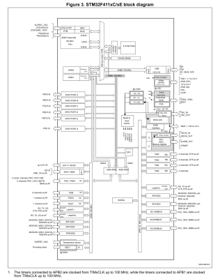
Here the biggest changes are probably in the memory layout, along with the number of certain types of peripherals. Feel free to compare along with us in the block diagrams.
A significant change between F103 and F4xx is that the GPIO peripherals were moved off the Advanced Peripheral Bus (APB) onto the AHB. AHB is the high-performance bus, for high bandwidth, low-latency operations. It is connected directly to the Cortex-M core via the AHB bus matrix. The APB on the other hand is a simpler bus, with no burst operations. Accessing peripherals on the APB from the Cortex-M core requires that the instructions pass over the AHB-to-APB bridge to the APB.
This should mean that GPIO operations are faster on the F4xx MCUs, especially with high-frequency operations. In addition, the I/O pin multiplexing on the F4xx MCUs changed to only allow one alternate function (AF) to be defined for a single GPIO pin. This corresponds to the integration of AF registers in the GPIO peripheral.
A big change is also seen in the RTC peripheral, which on the STM32F1 family is a simple 32-bit counter with programmable prescaler and an alarm register. On the STM32F4xx the RTC peripheral implements a full calendar, with sub-seconds, seconds, minutes, hours, days, months and years. It also has an alarm which can be triggered by any of these calendar fields, as well as an event time-stamp feature and a digital calibration circuit.
While DMA, the FLASH interface and Interrupts also see some changes, these are fairly minor and only of relevance when doing bare-metal programming. The one real gotcha with the F4xx chips is that in place of two 12-bit ADCs with 16 shared channels, the F401 and F411 have a single 12-bit ADC. For the trade, the ADC is marginally faster on the F4xx (2.4 Msps versus 2 Msps on the F103) and has a lower minimum voltage supply requirement of 1.7 V -1.8 V.
The Pills
Comparison of Blue and Black pill boards. Clone STM32F103 at top and STM32F411 on the bottom.
The differences between the two boards are quite stark, even beyond the soldermask color. The board which I am comparing with here is the STM32F411 version, which incidentally seems to be the most popular version when I searched for these boards on the German Amazon website.
The USB connector changed from micro USB-B to USB-C, the MCU package is a 48-pin UFQFPN instead of a 48-pin LQFP, we get an extra user button, and the HSE and LSE oscillators are much smaller. The boot mode pins are gone, but we get a boot mode button instead. We keep the same user-controlled LED on PC13, but the pin-out on the sides of the boards are not 100% compatible. Finally, one ‘Ground’ pin has been replaced with a 5 V pin. (!)
Flipping the boards over, the F103 board features a heap of passives and one IC, while the F411 board is clean except for a footpring for an SPI ROM footprint that fits an W25Q32JVSSIQ 32 Mbit SPI Flash ROM, for instance. This could be used to add a configuration ROM or similar.
Underside of the F103 Blue Pill and F411 Black Pill boards.
Beyond these differences, programming and debugging the board stays the same. One can use serial programming, with genuine STM32 MCUs, Single Wire Debug (SWD) via the four-pin break-out header, or the USB port if a suitable bootloader is installed. The schematic for the board is also available, which refers to the board as the ‘MiniF4’. This schematic also reveals without having to pull out the DMM that the user button is connected to PA0 without pull-up or pull-down resistor.
The Software
The STM32F4 family of MCUs is fully supported by ST’s CMSIS F4 device files, as well as its hardware abstraction layer (HAL) framework. Some may prefer to use ST’s STM32CubeMX software to auto-generate the hardware configuration and setup code.
STM32Duino also shows both the F401 and F411 boards to be supported. Those who are more inclined to meddle with tiny non-venomous snakes should be relieved to know that there are multiple MicroPython definitions for the boards, for the F401 and F411, as well this MicroPython board definition for the F411 version of the board. This means that at least as far as Arduino and MicroPython goes, existing code for F103 boards should run with minimal changes on F401 and F411 boards, keeping in mind potential changes to GPIO and AF pins.
In my own Nodate STM32 project I have added a board definition for the F411 board version as well. The fact of the matter is that these ‘Pill’ boards are such basic break-out boards for STM32 MCUs that very little support is needed. Besides the MCU on the board there’s just the LED on PC13 and a switch on PA0 if one’s framework is the type that abstracts such details away.
Conclusion
There comes a time when one has to move on. Considering that the STM32F103 is part of ST’s first-ever generation of Arm Cortex-M-based MCUs should already hint at that the time may have come for the Cortex-M3. As I noted in my recent article on STM32F103 clone chips, the supply of F103 ‘Blue Pill’ boards has recently become flooded with fakes, clones and brazen imitations of the genuine STM32F103. This makes it hard to even get such a board. Unless one is ready to validate and accept certain of these (admittedly quite good) F103 clone MCUs.
Meanwhile these F401/F411-based ‘Black Pill’ boards do not seem to have any issues with clones or fakes so far, cost roughly the same per unit as the older F103 ‘Blue Pill’, and unless you absolutely need the second ADC unit, are a better deal all-around. Software support should pose no obstacles either, with even details like the user LED using the exact same pin.
Just make sure that that you keep the slightly different pin-out of the F4xx boards in mind (i.e. the new 5 V pin), and double-check against the F401 or F411 reference manual to ensure that the peripherals one uses in a project are still on the same pins after recompiling for the new board. For new projects, using these new boards seems like a no-brainer, which is why I’m pretty sure that I’ll be stocking up on them.
What will your stockpile of cheap STM32 development boards look like the coming years? Will you be switching to F4 MCUs, or sticking with those F103 boards, if only because you bought 75 of them in an auction once and still haven’t used them up? Do you have any special use cases that make the F103 more suitable for your projects? Please let us know in the comments.
Ever wanted your own gesture-controlled robot arm? [EbenKouao]’s DIY Arduino Robot Arm project covers all the bases involved, but even if a robot arm isn’t your jam, his project has plenty to learn from. Every part is carefully explained, complete with source code and a list of required hardware. This approach to documenting a project is great because it not only makes it easy to replicate the results, but it makes it simple to remix, modify, and reuse separate pieces as a reference for other work.
[EbenKouao] uses a 3D-printable robotic gripper, base, and arm design as the foundation of his build. Hobby servos and a single NEMA 17 stepper take care of the moving, and the wiring and motor driving is all carefully explained. Gesture control is done by wearing an articulated glove upon which is mounted flex sensors and MPU6050 accelerometers. These sensors detect the wearer’s movements and turn them into motion commands, which in turn get sent wirelessly from the glove to the robotic arm with HC-05 Bluetooth modules. We really dig [EbenKouao]’s idea of mounting the glove sensors to this slick 3D-printed articulated gauntlet frame, but using a regular glove would work, too. The latest version of the Arduino code can be found on the project’s GitHub repository.
Most of the parts can be 3D printed, how every part works together is carefully explained, and all of the hardware is easily sourced online, making this a very accessible project. Check out the full tutorial video and demonstration, embedded below.
Ever wanted your own gesture-controlled robot arm? [EbenKouao]’s DIY Arduino Robot Arm project covers all the bases involved, but even if a robot arm isn’t your jam, his project has plenty to learn from. Every part is carefully explained, complete with source code and a list of required hardware. This approach to documenting a project is great because it not only makes it easy to replicate the results, but it makes it simple to remix, modify, and reuse separate pieces as a reference for other work.
[EbenKouao] uses a 3D-printable robotic gripper, base, and arm design as the foundation of his build. Hobby servos and a single NEMA 17 stepper take care of the moving, and the wiring and motor driving is all carefully explained. Gesture control is done by wearing an articulated glove upon which is mounted flex sensors and MPU6050 accelerometers. These sensors detect the wearer’s movements and turn them into motion commands, which in turn get sent wirelessly from the glove to the robotic arm with HC-05 Bluetooth modules. We really dig [EbenKouao]’s idea of mounting the glove sensors to this slick 3D-printed articulated gauntlet frame, but using a regular glove would work, too. The latest version of the Arduino code can be found on the project’s GitHub repository.
Most of the parts can be 3D printed, how every part works together is carefully explained, and all of the hardware is easily sourced online, making this a very accessible project. Check out the full tutorial video and demonstration, embedded below.
From his comments about the noisy image and limited controls, we’re going to go out on a limb and assume [Andrew Jeddeloh] isn’t a huge fan of using his Epson V550 for scanning film. But is it really irredeemable? That’s what he set out to determine in a recent series of posts on his blog, and from what we can tell, it’s not looking good for the old Epson.
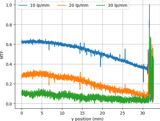
The first post attempts to quantify the optical capabilities of the scanner by determining its modulation transfer function (MTF), point spread function (PSF), and comparing its horizontal and vertical resolution. As you might expect, the nuances of these measurements are a bit beyond the average user. The short version of his analysis is that the scanner’s slide frame does indeed seem to be holding objects at the proper “sweet spot” for this particular image sensor; meaning that contrary to the advice he’d seen online, there’s nothing to be gained by purchasing custom film or slide holders.
MTF versus height of film from bed.
While investigating the optical properties of the scanner, [Andrew] became curious about the automatic focus options offered by the VueScan software he was using. The images produced appeared to be identical regardless of what option he selected, and he began to suspect the feature wasn’t actually doing anything. To confirm his theory, he wrote a shim program that would sit between the proprietary VueScan program and the V550 driver and log all of the data passing between them.
After tweaking various options and comparing the captured data streams, [Andrew] determined that enabling automatic focus in VueScan doesn’t do anything. At least, not with his scanner. He did notice a few extra bytes getting sent to the driver depending on which focus options were selected, but the response from the scanner didn’t change. He thinks the program likely has some kind of generic framework for enabling these kind of features on supported hardware, and it’s just mistakenly showing the autofocus options for a scanner that doesn’t support it.
From his comments about the noisy image and limited controls, we’re going to go out on a limb and assume [Andrew Jeddeloh] isn’t a huge fan of using his Epson V550 for scanning film. But is it really irredeemable? That’s what he set out to determine in a recent series of posts on his blog, and from what we can tell, it’s not looking good for the old Epson.
The first post attempts to quantify the optical capabilities of the scanner by determining its modulation transfer function (MTF), point spread function (PSF), and comparing its horizontal and vertical resolution. As you might expect, the nuances of these measurements are a bit beyond the average user. The short version of his analysis is that the scanner’s slide frame does indeed seem to be holding objects at the proper “sweet spot” for this particular image sensor; meaning that contrary to the advice he’d seen online, there’s nothing to be gained by purchasing custom film or slide holders.
MTF versus height of film from bed.
While investigating the optical properties of the scanner, [Andrew] became curious about the automatic focus options offered by the VueScan software he was using. The images produced appeared to be identical regardless of what option he selected, and he began to suspect the feature wasn’t actually doing anything. To confirm his theory, he wrote a shim program that would sit between the proprietary VueScan program and the V550 driver and log all of the data passing between them.
After tweaking various options and comparing the captured data streams, [Andrew] determined that enabling automatic focus in VueScan doesn’t do anything. At least, not with his scanner. He did notice a few extra bytes getting sent to the driver depending on which focus options were selected, but the response from the scanner didn’t change. He thinks the program likely has some kind of generic framework for enabling these kind of features on supported hardware, and it’s just mistakenly showing the autofocus options for a scanner that doesn’t support it.
Linker scripts are one of those things which nobody who does software development really wants to deal with, but like many things in life sometimes they are inevitable to make things work. Although one could keep pretending linker scripts do not exist and let IDEs handle such pesky details, some of us suffer from this unfortunate condition called ‘curiosity’ and just have to know. People like [Thea].
Recently, [Thea] wrote a blog post on exactly what the linker script generated by the Microchip IDE for a Cortex-M-based SAM D21 project does. The result is a nicely annotated overview of the file’s contents, accompanied by links to the Arm and GCC documentation as well as other references where appropriate. The entire linker script (.ld file) can be viewed on GitHub. With the SAM D21 being a popular choice for Arduino and Arduino-compatible board, this article is a good starting point to understanding what a linker script does and how it affects one’s project.
For other (Cortex-M) MCUs this linker script is also useful as a starting point. Especially knowing which sections are required and what changing them affects in the final (ELF) binary and the firmware that is ultimately written to the MCU. We recently covered linker scripts for Cortex-M as well, along with the concept of memory-mapped I/O.
[Chuck] likes the ability of Simplify3D to add support to parts of a model manually. However, not everyone wants to spend $150 for a slicer, so he’s shared how to install a plugin that allows you to do the same trick in Cura.
The plugin is “Cylindric Custom Support.” That doesn’t sound very exciting, but you get five choices of shapes you can create custom supports easily. There are also size and angle parameters you can use to customize the effect.
The cylinder and cube choices are pretty obvious, but the explanation of abutment support is useful. [Chuck] shows how this can be more efficient than the default support.
Of course, the proof is in the print, and the model looked pretty good for a first attempt. [Chuck] mentions that he should have made larger supports, which is possible, of course.
We liked his earlier video on tree supports, which also talks about support in general, so if you aren’t doing much with support in Cura, you might check that one out, too. It explains a lot of the support options you can tune.
We used to think we really wanted water-soluble support, but modern slicers do a good job of making support material easy to remove. You can also try providing a release agent. If you want some more background on support, here you go.
For map-lovers like [Christopher Getschmann], poring over a quality map can be as satisfying as reading a good book. Good maps can be hard to come by, though, especially at a scale worth looking at, or worth using as adornment on a dull, lifeless wall. The solution is obvious: build a wall-mount CNC plotter to draw maps directly on the wall.
[Christopher] began his map quest by scraping world map data from a number of sources, including OpenStreetMap, Natural Earth, and GEBCO. This gave him data for coastlines, terrain, and bathymetry — enough for a map of the world large enough to fill a wall. Since the scale of the map would preclude the use of even a large-format inkjet printer, [Christopher] set about building a wall-covering pen-plotter to render the map. The CoreXY-style plotter is large, but still light enough to hang on the wall while it works, and to be repositioned to cover a larger area.
The plotter runs on steppers driven by ultra-quiet Trinamic TMC5160 drivers, so the plotter wouldn’t be a nuisance while it worked. The map was plotted on eight pieces of cardboard mounted directly to the wall, filling the 2- x 3-meter space almost entirely. Landmasses and elevation contours were plotted as continuous lines in black ink, while bathymetric data was rendered in blue ink as cross-hatching with variable spacing, to make deeper oceans darker blue.
We find [Christopher]’s map breathtaking, all the more so considering the work that went into making it. It would be interesting to find alternate uses for the plotter, which reminds us a little of a cross between a draw-bot and a Maslow vertical CNC router, now that it’s done with its cartographic duties.
You may not have noticed, but we here at Hackaday really love our clicky stuff. Clicky mechanical keyboards, unnecessarily noisy flip-dot displays, and pretty much anything made with a lot of relays — they all grab our attention, in more ways than one. So it’s with no small surprise that we appear to have entirely missed perhaps the clickiest build of all: a fully operational 8-bit computer using nothing but relays.
What’s even more amazing about our failure to find and feature [Paul Law]’s excellent work is that he has been at it for the better part of a decade now. The first post on his very detailed and very well-crafted blog describing the build dates from 2013, when he was just testing LEDs in the arithmetic-logic unit (ALU). Since then, [Paul] has made incredible progress, building module after module, each containing a small portion of the computer’s functionality. The modules plug into card cages with backplanes to connect them, and the whole thing lives in an enclosure made from aluminum extrusion and glossy black panels for a truly sleek look. The computer is incredibly compact for something that uses 400+ DPDT relays to do its thinking.
In addition to the blog, [Paul] has a criminally undersubscribed YouTube channel with a quite recent series going over the computer in depth. We included the overall tour below, but you should really check out the rest of the videos to appreciate how much work went into this build. We’ve seen relay computers ranging in size from single-board to just plain ludicrous, but this one really takes the prize for fit and finish as well as functionality.
Have you dipped your toe into the SDR ocean? While hacker software-defined radio has been a hot topic for years now, it can be a little daunting to try it out for the first time. Here’s your change to get your legs under you with the SDR overview workshop presented by Josh Conway during the 2020 Hackaday Remoticon.
Josh’s presentation starts with a straightforward definition of SDR before moving to an overview of the hardware and software that’s out there. Hardware designs for radios can be quite simple to build, but they’ll be limited to a single protocol — for instance, an FM radio can’t listen in on 433 Mhz wireless doorbell. SDR breaks out of that by moving to a piece of radio hardware that can be reconfigured to work with protocols merely by making changes to the software that controls it. This makes the radio hardware more expensive, but also means you can listen (and sometimes transmit) to a wide range of devices like that wireless doorbell or automotive tire pressure sensors, but also radio-based infrastructure like airplane transponders and weather satellites.
This is the quickstart you want since it explains a lot of topis at just the right depth. The hardware overview covers RTL-SDR, ADALM-PLUTO, HackRF, KerberosSDR, and BladeRF (which we just featured over the weekend used on the WiFi procotol). For software, Josh recaps GQRX, SDR#, SDRAngel, ShinySDR, Universal Radio Hacker, Inspectrum, SigDigger, RPITX, GnuRadio Companion, and REDHAWK. He also takes us through a wide swath of the antenna types that are out there before turning to questions from the workshop attendees.
If SDR is still absent in your toolbox, now’s a great time to give it another look. Once you’ve made it through the ‘hello world’ stage, there’s plenty to explore like those awesome RF Emissions testing tricks we as in another Remoticon talk.
When the Space Shuttle Atlantis rolled to a stop on its final mission in 2011, it was truly the end of an era. Few could deny that the program had become too complex and expensive to keep running, but even still, humanity’s ability to do useful work in low Earth orbit took a serious hit with the retirement of the Shuttle fleet. Worse, there was no indication of when or if another spacecraft would be developed that could truly rival the capabilities of the winged orbiters first conceived in the late 1960s.
While its primary function was to carry large payloads such as satellites into orbit, the Shuttle’s ability to retrieve objects from space and bring them back was arguably just as important. Throughout its storied career, sensitive experiments conducted at the International Space Station or aboard the Orbiter itself were returned gently to Earth thanks to the craft’s unique design. Unlike traditional spacecraft that ended their flight with a rough splashdown in the open ocean, the Shuttle eased itself down to the tarmac like an airplane. Once landed, experiments could be quickly unloaded and transferred to the nearby Space Station Processing Facility where science teams would be waiting to perform further processing or analysis.
Atlantis is towed from the runway for payload processing.
For 30 years, the Space Shuttle and its assorted facilities at Kennedy Space Center provided a reliable way to deliver fragile or time-sensitive scientific experiments into the hands of researchers just a few hours after leaving orbit. It was a valuable service that simply didn’t exist before the Shuttle, and one that scientists have been deprived of ever since its retirement.
Until now. With the successful splashdown of the first Cargo Dragon 2 off the coast of Florida, NASA is one step closer to regaining a critical capability it hasn’t had for a decade. While it’s still not quite as convenient as simply rolling the Shuttle into the Orbiter Processing Facility after a mission, the fact that SpaceX can guide their capsule down into the waters near the Space Coast greatly reduces the time required to return experiments to the researchers who designed them.
On Dragon’s Wings
While it took nearly ten years to resume crewed launches from American soil after the retirement of the Space Shuttle, there wasn’t nearly as much of a downtime for cargo flights. SpaceX put their first Dragon capsule into orbit in 2010, and just over a year after the final flight of Atlantis, they were ready to begin regular resupply missions to the International Space Station. Not only could the privately developed craft carry a combined 6,000 kilograms (13,000 pounds) of pressurized and unpressurized cargo to the orbiting outpost, it could also bring approximately 3,000 kg (6,600 lbs) back down to Earth.
By 2012, SpaceX had already sent a Dragon to the ISS.
In comparison, the Shuttle could safely land with around 14,400 kg (31,700 lbs) packed in its cavernous cargo bay. But realistically, that capacity was intended for hauling satellites and was completely overkill for simply returning racks of scientific experiments. Price was also a consideration: a Dragon mission cost NASA just a fraction of what a Shuttle flight did. Combined with the much higher launch cadence of the Dragon, it’s clear which vehicle was better suited to performing regular “milk runs” up to the ISS and back.
But there was a downside. Despite SpaceX’s stated intention to one day perform pin-point propulsive landings with the Dragon, the small spacecraft ended up splashing down in the ocean under parachutes just like the Apollo and Gemini capsules before it. This meant returning to Earth on a Dragon was a much rougher ride than what the Shuttle offered. While not a problem for many payloads, it could be a ruinous experience for sensitive experiments such as those designed to study crystal growth in microgravity.
Further complicating matters was the fact that the capsule came down in the Pacific Ocean, several hundred kilometers off the coast. This made recovery operations easier for the California-based SpaceX, but as NASA lacked suitable payload processing facilities on the West Coast, returning cargo would need to be transported to Johnson Space Center in Houston or all the way back to Kennedy Space Center. The prospect of experiments potentially having to endure a cross-country flight before they could be released to scientists made certain research difficult or impossible to accomplish.
The Human Element
While hardly ideal, landing cargo and experiments on the West Coast and flying them back to Florida was still better than having to transport them back from Kazakhstan if they flew on a Soyuz. But it wouldn’t quite do when it came time for SpaceX to start carrying astronauts as part of the Commercial Crew Program. NASA wanted the primary splashdown point for the new Crew Dragon to be as close to Kennedy Space Center as possible to leverage the existing Shuttle era resources and facilities, with a splashdown in the Gulf of Mexico reserved for contingencies.
GO Navigator with Crew Dragon onboard.
This required a considerable expansion of SpaceX’s recovery capabilities. Two ships, GO Searcher and GO Navigator, were procured by the company and outfitted with medical facilities, a helipad, and a lifting apparatus on the stern for hoisting the floating Crew Dragon capsule onto the deck. For redundancy the two craft are virtually identical and can be deployed simultaneously.
With the operational assets and trained personnel moved to East Coast for Crew Dragon, recovering the cargo variant of the spacecraft in California no longer made fiscal sense. Besides, given how similar the two vehicles are, experience gained while pulling the Cargo Dragon from the ocean would serve to improve crewed recovery operations. As NASA’s requirements state that astronauts must egress the capsule within 60 minutes of splashdown, the teams need all the practice they can get.
Beyond the faster delivery time, Cargo Dragon has a number of other advantages over its predecessor. The upgraded capsule has increased payload capacity, twice the number of climate controlled lockers for storing sensitive materials, and a fully autonomous docking system that reduces the workload for astronauts aboard the orbiting outpost. It can also be more easily refurbished for reuse, which not only lowers costs but allows for a higher launch cadence than would be possible otherwise.
Chasing the Dream
With a helicopter waiting to take time-sensitive payloads from the recovery ship to the Space Station Processing Facility, SpaceX can now deliver experiments to scientists between four and nine hours after splashdown. This is a vast improvement over what was possible previously, and arguably the best that can be realistically expected for an off-shore operation. But it’s still not a fast as the Space Shuttle.
Ultimately, having to pull the spacecraft from the ocean and transporting the human crew members or scientific payloads back to land via helicopter will always take longer than simply landing the vehicle at a designated facility. Since SpaceX is no longer pursuing targeted propulsive landings with their Dragon spacecraft, that means another company will have to step up to meet the challenge of truly rapid payload return.
Dream Chaser prototype during testing.
As it so happens, that’s precisely what the Sierra Nevada Corporation hopes to do with their Dream Chaser spaceplane. Currently slated to fly in 2022 as part of NASA’s Commercial Resupply Services-2 program, the vehicle can return as much as 1,750 kg (3,860 lbs) of cargo to a gentle horizontal landing. Being a quarter the size of the Space Shuttle Orbiter, the Dream Chaser has the advantage of being able to use any runway long enough to accommodate a large passenger plane.
This ability to land essentially anywhere on the planet has clear benefits for international scientific collaboration. But more importantly, when the company completes work on their human-rated variant of the spacecraft, it could be a potentially life-saving capability in the event that a medical emergency necessitates a crew member be transported back to Earth as quickly as possible.
Space Force Leads the Way
The fact that multiple commercially operated spacecraft are now in competition to bring cargo and crew members to the International Space Station and beyond is an incredible achievement. It’s something that many people in the industry believed would never happen, and things are just getting started. The next decade will see several more vehicles and boosters come online, all fighting to be the fastest, most reliable, and of course, cheapest. The democratization of space has officially begun.
The X-37B on the Shuttle runway at Kennedy Space Center.
But as has often been the case historically, it seems that the military is considerably ahead of the curve. The Boeing X-37B spaceplane, now being operated by the newly formed Space Force, is an ideal platform for orbital research and development that in many ways exceeds the capabilities of its commercial peers.
Naturally there’s still a lot we don’t know about the secretive craft, but its ability to conduct free-flying experiments and return scientific payloads from space to a soft runway landing has been publicly demonstrated several times. Being fully autonomous, the X-37B is also able to remain in orbit for far longer than any crewed vehicle. This provides a unique opportunity to conduct long-duration experiments in complete isolation; something that simply isn’t possible on the bustling International Space Station.
As you might expect for a shadowy military operation, most of the research being conducted aboard the X-37B is classified. Some believe the vehicle is designed to evaluate new reconnaissance equipment and techniques, while others think its a test platform for anti-satellite weaponry. But there are signs that the Space Force is willing to share its miniature spaceplane with non-military researchers, with the last launch in May carrying a record number of NASA experiments.
In the end, none of these vehicles can carry more scientific payload than the Space Shuttle, and to date, only the government-operated craft is able to approach the sort of rapid turnaround necessary for the truly time-sensitive experiments. But for the first time in history there’s an array of competitive choices available to researchers who want to get their payload into space and back down in one piece; and that’s definitely a step in the right direction.
So far in the $50 Ham series, I’ve concentrated mainly on the VHF and UHF bands. The reason for this has to do mainly with FCC rules, which largely restrict Technician-level licensees to those bands. But there’s a financial component to it, too; high-frequency (HF) band privileges come both at the price of learning enough about radio to pass the General license test, as well as the need for gear that can be orders of magnitude more expensive than a $30 handy-talkie radio.
But while HF gear can be expensive, not everything needed to get on the air has to be so. And since it’s often the antenna that makes or breaks an amateur radio operator’s ability to make contacts, we’ll look at a simple but versatile antenna design that can be adapted to support everything from a big, powerful base station to portable QRP (low-power) activations in the field: the end-fed half-wave antenna.
Making a Match
There are plenty of hams out there for whom antenna building is the be-all and end-all of the hobby. I get that; there’s a non-zero amount of wizardry that goes into designing an antenna that will do what you want it to do electrically, and plenty of engineering involved in making sure it stands up to the elements. I think the latter aspect of antenna building is more attractive to me personally. Getting an antenna to survive wind, snow, sun, and rain is an interesting challenge, so I tend to spend more time thinking about the mechanical aspects of design that someone has already worked the RF bugs out of.
So I set out looking for an antenna that would work for my situation. Perhaps the easiest antenna to build is the classic half-wave dipole. These have two elements, each one-quarter of the design wavelength, radiating out from a central feed point, which is where the coaxial cable feedline attaches. There are elaborations and complications, of course, but the basic issue for me is the central feed point. My shack is located at the very back corner of my property, so it’s difficult to rig an antenna like that without a long feedline, which can introduce unacceptable signal losses. Plus, a dipole for the 80-meter band would be 40 meters end-to-end, and that would be hard to fit across my long, narrow suburban lot.
For my purposes, the end-fed half-wave (EFHW) antenna is a good choice. It’s exactly what it sounds like: a chunk of wire one-half of a wavelength long (in my case, 40 meters long so I can work the 80 meter band) that is fed from its end. But it’s not as simple as cutting a 40 meter long piece of wire and sticking it on your radio. The problem is that the impedance of an antenna varies as the feedpoint moves away from the center. The impedance increases all the way up to about 2,500 ohms when the feedpoint reaches the end of the wire, which would be a very bad match indeed for a transceiver expecting a 50 ohm load.
To fix this, EFHW antennas need a transformer to match impedances. When used to match impedance between a balanced antenna, like a dipole, and an unbalanced feedline, like coaxial cable, these are referred to as “baluns”. In this case, though, both the antenna and the coax feedline are unbalanced, so the transformer I built is technically an “unun”. Whatever you call it, it’s a pretty easy build.
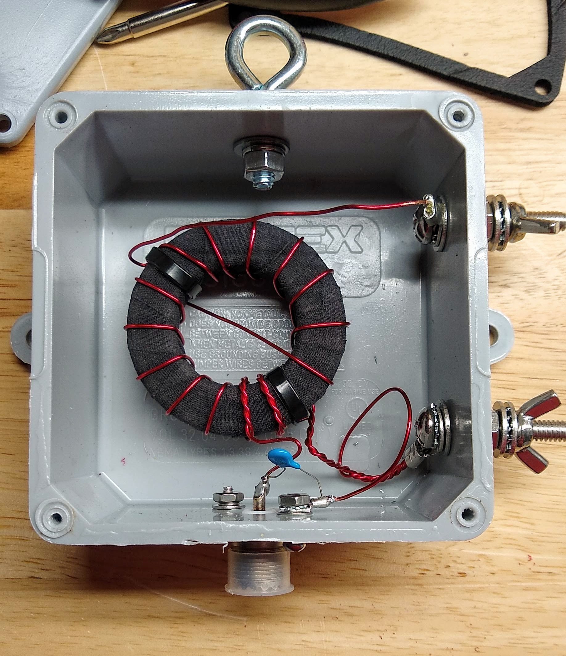
My 49:1 matching transformer, mounted and ready to go outside. I considered potting the hole thing in epoxy, but decided against it.
I followed the excellent instructions provided by Steve Nichols (G0KYA) to wind my 49:1 autotransformer. It’s basically just big ferrite toroid core — I got mine from eBay, but there are plenty of options on Amazon — with a few windings of magnet wire. My core is an FT-240-61, which means its outside diameter is 2.4 inches and it’s made of type 61 material. I used 18 AWG magnet wire for the windings. While I was winding it, I noticed that the lacquer coating on the magnet wire was getting nicked by the edges of the ferrite core. I rewound it after covering the toroid with cloth friction tape to cushion the edges a bit — shorts would be no bueno in something designed to handle 100 Watts of transmitter output.
Like I said, a lot of the fussing I did with this transformer had to do with making it work mechanically. I mounted it into a sturdy plastic electrical enclosure and provided stainless steel fittings for connecting the antenna wire and the ground connection. I also installed an eye bolt to tether the antenna wire. A good-quality SO-239 socket for the feedline connection and a 100 pF high-voltage capacitor for better matching on the higher frequency bands completed the transformer. With luck, this antenna should cover 80 m to 10 m bands.
Pushing Rope
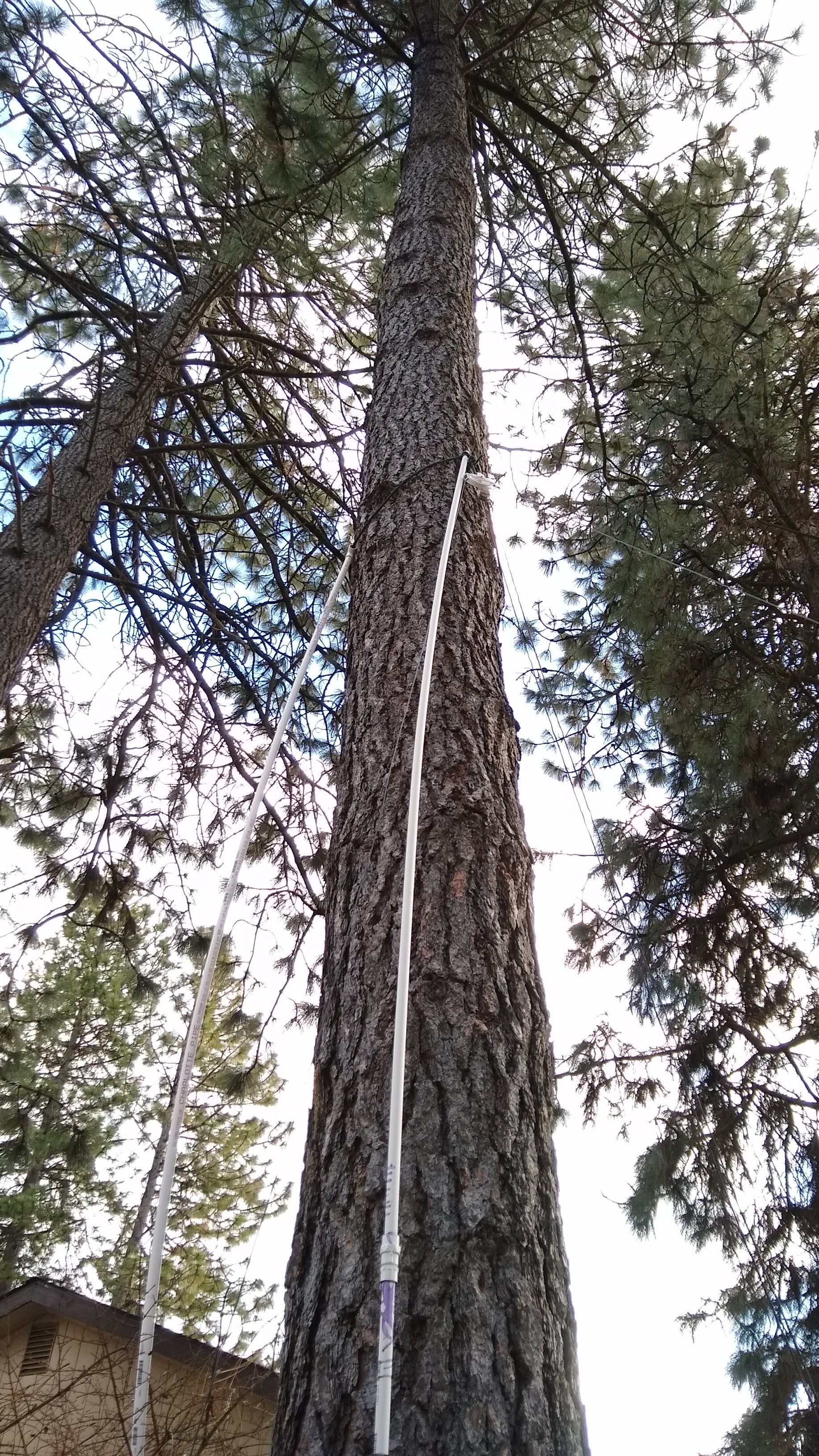
My method for placing a pulley up a tree from the ground. It would have work better on a tree with smoother bark.
As luck would have it, my lot is just about 150 feet deep, and I’m both blessed and cursed by a lot of very tall, very sturdy Ponderosa pines. The length of my lot and the location of the trees allows for a full 40-meter wire in a sort of “inverted-L” configuration. My plan was to slope the wire from the transformer up as far as possible in the first tree, then run it horizontally to an anchor point in a second tree.
This sounds far, far easier than it actually is. While many hams have had good luck suspending antennas from lines lofted over branches, my pine trees have all been pruned of their lower branches, with the first living branches more than 40′ (12 meters) above the ground. I opted for a “work smarter” approach and came up with an idea to basically push a loop of rope up the tree using PVC pipe as a push stick. Although the roughness of the Ponderosa bark constantly snagged the nylon rope and the PVC pipe flopped around as I added sections , it actually worked well enough to get the anchor point about 25′ (7.5 m) above the ground — not much higher than I could have gotten with my 24′ ladder, but with a whole lot less risk of falling to my death.
The anchor point was set in the other tree using a similar method, which drew a lot of attention from the neighbors. One should always seize such opportunities to do a little “ham goodwill” outreach, and I assured the neighbors that I wouldn’t be sterilizing their kids or interfering with their TV reception. In an example of karma, though, the tree I was working in decided to shed a dead branch the next day, which came down and damaged my neighbor’s Durango. It clearly came from much higher in the tree than I was working, but it still caused a little bit of the old stink eye.
Sway relief on the anchor end. Note the safety line that runs through the bore of the spring, just in case it breaks.
One of the most important parts of using trees as anchors for long-wire antennas is dealing with sway. Trees move around quite a bit, and if you anchor a wire tightly between two trees without allowing for them to move with the wind, sadness will ensue. And yet, you want your wire to stay more or less taut, since its shape affects its performance. There are a couple of ways to deal with this, and I chose to use clothesline pulleys at both my anchor points. At the midpoint, the wire runs through the pulley; at the end anchor, the wire is tied off to a length of strong nylon cord through a dogbone insulator. That cord runs through the pulley and down the trunk of the tree to an anchor point through a strong spring. When the trees sway, the antenna can extend or retract by several inches without sagging or snapping.
On the Air at Last
I have to admit that this installation isn’t actually complete yet. Antennas really should be properly grounded, and I’m keen to pound a ground rod in near the transformer. However, both the mains feeder for my house and the primary feeder for the entire neighborhood are buried directly under our back fence, making this a high-risk endeavor. As good as underground location services are, I’m not keen to test their precision with my precious self. So I’m going to wait for a decent ground.
Still, I couldn’t help but want to try this antenna out, so to keep RF out of the shack, I would a 10-turn air-core choke on the feedline and hooked it up. I haven’t made any QSOs yet, but using WSPR, the Weak Signal Propagation Reporter system, I was able to reach four continents over a 24-hour period on the 80-, 40-, 30-, and 20-meter bands.
The world on one antenna: 24 hours of WSPR reports on 80, 40, 30, and 20 meters.
And speaking of WSPR, that and other digital modes are what we’ll be talking about in the next installment of the $50 Ham. Spoiler alert: despite my previous gripes, I think I’m falling in love with ham radio again.
So far in the $50 Ham series, I’ve concentrated mainly on the VHF and UHF bands. The reason for this has to do mainly with FCC rules, which largely restrict Technician-level licensees to those bands. But there’s a financial component to it, too; high-frequency (HF) band privileges come both at the price of learning enough about radio to pass the General license test, as well as the need for gear that can be orders of magnitude more expensive than a $30 handy-talkie radio.
But while HF gear can be expensive, not everything needed to get on the air has to be so. And since it’s often the antenna that makes or breaks an amateur radio operator’s ability to make contacts, we’ll look at a simple but versatile antenna design that can be adapted to support everything from a big, powerful base station to portable QRP (low-power) activations in the field: the end-fed half-wave antenna.
Making a Match
There are plenty of hams out there for whom antenna building is the be-all and end-all of the hobby. I get that; there’s a non-zero amount of wizardry that goes into designing an antenna that will do what you want it to do electrically, and plenty of engineering involved in making sure it stands up to the elements. I think the latter aspect of antenna building is more attractive to me personally. Getting an antenna to survive wind, snow, sun, and rain is an interesting challenge, so I tend to spend more time thinking about the mechanical aspects of design that someone has already worked the RF bugs out of.
So I set out looking for an antenna that would work for my situation. Perhaps the easiest antenna to build is the classic half-wave dipole. These have two elements, each one-quarter of the design wavelength, radiating out from a central feed point, which is where the coaxial cable feedline attaches. There are elaborations and complications, of course, but the basic issue for me is the central feed point. My shack is located at the very back corner of my property, so it’s difficult to rig an antenna like that without a long feedline, which can introduce unacceptable signal losses. Plus, a dipole for the 80-meter band would be 40 meters end-to-end, and that would be hard to fit across my long, narrow suburban lot.
For my purposes, the end-fed half-wave (EFHW) antenna is a good choice. It’s exactly what it sounds like: a chunk of wire one-half of a wavelength long (in my case, 40 meters long so I can work the 80 meter band) that is fed from its end. But it’s not as simple as cutting a 40 meter long piece of wire and sticking it on your radio. The problem is that the impedance of an antenna varies as the feedpoint moves away from the center. The impedance increases all the way up to about 2,500 ohms when the feedpoint reaches the end of the wire, which would be a very bad match indeed for a transceiver expecting a 50 ohm load.
To fix this, EFHW antennas need a transformer to match impedances. When used to match impedance between a balanced antenna, like a dipole, and an unbalanced feedline, like coaxial cable, these are referred to as “baluns”. In this case, though, both the antenna and the coax feedline are unbalanced, so the transformer I built is technically an “unun”. Whatever you call it, it’s a pretty easy build.
My 49:1 matching transformer, mounted and ready to go outside. I considered potting the hole thing in epoxy, but decided against it.
I followed the excellent instructions provided by Steve Nichols (G0KYA) to wind my 49:1 autotransformer. It’s basically just big ferrite toroid core — I got mine from eBay, but there are plenty of options on Amazon — with a few windings of magnet wire. My core is an FT-240-61, which means its outside diameter is 2.4 inches and it’s made of type 61 material. I used 18 AWG magnet wire for the windings. While I was winding it, I noticed that the lacquer coating on the magnet wire was getting nicked by the edges of the ferrite core. I rewound it after covering the toroid with cloth friction tape to cushion the edges a bit — shorts would be no bueno in something designed to handle 100 Watts of transmitter output.
Like I said, a lot of the fussing I did with this transformer had to do with making it work mechanically. I mounted it into a sturdy plastic electrical enclosure and provided stainless steel fittings for connecting the antenna wire and the ground connection. I also installed an eye bolt to tether the antenna wire. A good-quality SO-239 socket for the feedline connection and a 100 pF high-voltage capacitor for better matching on the higher frequency bands completed the transformer. With luck, this antenna should cover 80 m to 10 m bands.
Pushing Rope
My method for placing a pulley up a tree from the ground. It would have work better on a tree with smoother bark.
As luck would have it, my lot is just about 150 feet deep, and I’m both blessed and cursed by a lot of very tall, very sturdy Ponderosa pines. The length of my lot and the location of the trees allows for a full 40-meter wire in a sort of “inverted-L” configuration. My plan was to slope the wire from the transformer up as far as possible in the first tree, then run it horizontally to an anchor point in a second tree.
This sounds far, far easier than it actually is. While many hams have had good luck suspending antennas from lines lofted over branches, my pine trees have all been pruned of their lower branches, with the first living branches more than 40′ (12 meters) above the ground. I opted for a “work smarter” approach and came up with an idea to basically push a loop of rope up the tree using PVC pipe as a push stick. Although the roughness of the Ponderosa bark constantly snagged the nylon rope and the PVC pipe flopped around as I added sections , it actually worked well enough to get the anchor point about 25′ (7.5 m) above the ground — not much higher than I could have gotten with my 24′ ladder, but with a whole lot less risk of falling to my death.
The anchor point was set in the other tree using a similar method, which drew a lot of attention from the neighbors. One should always seize such opportunities to do a little “ham goodwill” outreach, and I assured the neighbors that I wouldn’t be sterilizing their kids or interfering with their TV reception. In an example of karma, though, the tree I was working in decided to shed a dead branch the next day, which came down and damaged my neighbor’s Durango. It clearly came from much higher in the tree than I was working, but it still caused a little bit of the old stink eye.
Sway relief on the anchor end. Note the safety line that runs through the bore of the spring, just in case it breaks.
One of the most important parts of using trees as anchors for long-wire antennas is dealing with sway. Trees move around quite a bit, and if you anchor a wire tightly between two trees without allowing for them to move with the wind, sadness will ensue. And yet, you want your wire to stay more or less taut, since its shape affects its performance. There are a couple of ways to deal with this, and I chose to use clothesline pulleys at both my anchor points. At the midpoint, the wire runs through the pulley; at the end anchor, the wire is tied off to a length of strong nylon cord through a dogbone insulator. That cord runs through the pulley and down the trunk of the tree to an anchor point through a strong spring. When the trees sway, the antenna can extend or retract by several inches without sagging or snapping.
On the Air at Last
I have to admit that this installation isn’t actually complete yet. Antennas really should be properly grounded, and I’m keen to pound a ground rod in near the transformer. However, both the mains feeder for my house and the primary feeder for the entire neighborhood are buried directly under our back fence, making this a high-risk endeavor. As good as underground location services are, I’m not keen to test their precision with my precious self. So I’m going to wait for a decent ground.
Still, I couldn’t help but want to try this antenna out, so to keep RF out of the shack, I would a 10-turn air-core choke on the feedline and hooked it up. I haven’t made any QSOs yet, but using WSPR, the Weak Signal Propagation Reporter system, I was able to reach four continents over a 24-hour period on the 80-, 40-, 30-, and 20-meter bands.
The world on one antenna: 24 hours of WSPR reports on 80, 40, 30, and 20 meters.
And speaking of WSPR, that and other digital modes are what we’ll be talking about in the next installment of the $50 Ham. Spoiler alert: despite my previous gripes, I think I’m falling in love with ham radio again.
So far in the $50 Ham series, I’ve concentrated mainly on the VHF and UHF bands. The reason for this has to do mainly with FCC rules, which largely restrict Technician-level licensees to those bands. But there’s a financial component to it, too; high-frequency (HF) band privileges come both at the price of learning enough about radio to pass the General license test, as well as the need for gear that can be orders of magnitude more expensive than a $30 handy-talkie radio.
But while HF gear can be expensive, not everything needed to get on the air has to be so. And since it’s often the antenna that makes or breaks an amateur radio operator’s ability to make contacts, we’ll look at a simple but versatile antenna design that can be adapted to support everything from a big, powerful base station to portable QRP (low-power) activations in the field: the end-fed half-wave antenna.
Making a Match
There are plenty of hams out there for whom antenna building is the be-all and end-all of the hobby. I get that; there’s a non-zero amount of wizardry that goes into designing an antenna that will do what you want it to do electrically, and plenty of engineering involved in making sure it stands up to the elements. I think the latter aspect of antenna building is more attractive to me personally. Getting an antenna to survive wind, snow, sun, and rain is an interesting challenge, so I tend to spend more time thinking about the mechanical aspects of design that someone has already worked the RF bugs out of.
So I set out looking for an antenna that would work for my situation. Perhaps the easiest antenna to build is the classic half-wave dipole. These have two elements, each one-quarter of the design wavelength, radiating out from a central feed point, which is where the coaxial cable feedline attaches. There are elaborations and complications, of course, but the basic issue for me is the central feed point. My shack is located at the very back corner of my property, so it’s difficult to rig an antenna like that without a long feedline, which can introduce unacceptable signal losses. Plus, a dipole for the 80-meter band would be 40 meters end-to-end, and that would be hard to fit across my long, narrow suburban lot.
For my purposes, the end-fed half-wave (EFHW) antenna is a good choice. It’s exactly what it sounds like: a chunk of wire one-half of a wavelength long (in my case, 40 meters long so I can work the 80 meter band) that is fed from its end. But it’s not as simple as cutting a 40 meter long piece of wire and sticking it on your radio. The problem is that the impedance of an antenna varies as the feedpoint moves away from the center. The impedance increases all the way up to about 2,500 ohms when the feedpoint reaches the end of the wire, which would be a very bad match indeed for a transceiver expecting a 50 ohm load.
To fix this, EFHW antennas need a transformer to match impedances. When used to match impedance between a balanced antenna, like a dipole, and an unbalanced feedline, like coaxial cable, these are referred to as “baluns”. In this case, though, both the antenna and the coax feedline are unbalanced, so the transformer I built is technically an “unun”. Whatever you call it, it’s a pretty easy build.
My 49:1 matching transformer, mounted and ready to go outside. I considered potting the hole thing in epoxy, but decided against it.
I followed the excellent instructions provided by Steve Nichols (G0KYA) to wind my 49:1 autotransformer. It’s basically just big ferrite toroid core — I got mine from eBay, but there are plenty of options on Amazon — with a few windings of magnet wire. My core is an FT-240-61, which means its outside diameter is 2.4 inches and it’s made of type 61 material. I used 18 AWG magnet wire for the windings. While I was winding it, I noticed that the lacquer coating on the magnet wire was getting nicked by the edges of the ferrite core. I rewound it after covering the toroid with cloth friction tape to cushion the edges a bit — shorts would be no bueno in something designed to handle 100 Watts of transmitter output.
Like I said, a lot of the fussing I did with this transformer had to do with making it work mechanically. I mounted it into a sturdy plastic electrical enclosure and provided stainless steel fittings for connecting the antenna wire and the ground connection. I also installed an eye bolt to tether the antenna wire. A good-quality SO-239 socket for the feedline connection and a 100 pF high-voltage capacitor for better matching on the higher frequency bands completed the transformer. With luck, this antenna should cover 80 m to 10 m bands.
Pushing Rope
My method for placing a pulley up a tree from the ground. It would have work better on a tree with smoother bark.
As luck would have it, my lot is just about 150 feet deep, and I’m both blessed and cursed by a lot of very tall, very sturdy Ponderosa pines. The length of my lot and the location of the trees allows for a full 40-meter wire in a sort of “inverted-L” configuration. My plan was to slope the wire from the transformer up as far as possible in the first tree, then run it horizontally to an anchor point in a second tree.
This sounds far, far easier than it actually is. While many hams have had good luck suspending antennas from lines lofted over branches, my pine trees have all been pruned of their lower branches, with the first living branches more than 40′ (12 meters) above the ground. I opted for a “work smarter” approach and came up with an idea to basically push a loop of rope up the tree using PVC pipe as a push stick. Although the roughness of the Ponderosa bark constantly snagged the nylon rope and the PVC pipe flopped around as I added sections , it actually worked well enough to get the anchor point about 25′ (7.5 m) above the ground — not much higher than I could have gotten with my 24′ ladder, but with a whole lot less risk of falling to my death.
The anchor point was set in the other tree using a similar method, which drew a lot of attention from the neighbors. One should always seize such opportunities to do a little “ham goodwill” outreach, and I assured the neighbors that I wouldn’t be sterilizing their kids or interfering with their TV reception. In an example of karma, though, the tree I was working in decided to shed a dead branch the next day, which came down and damaged my neighbor’s Durango. It clearly came from much higher in the tree than I was working, but it still caused a little bit of the old stink eye.
Sway relief on the anchor end. Note the safety line that runs through the bore of the spring, just in case it breaks.
One of the most important parts of using trees as anchors for long-wire antennas is dealing with sway. Trees move around quite a bit, and if you anchor a wire tightly between two trees without allowing for them to move with the wind, sadness will ensue. And yet, you want your wire to stay more or less taut, since its shape affects its performance. There are a couple of ways to deal with this, and I chose to use clothesline pulleys at both my anchor points. At the midpoint, the wire runs through the pulley; at the end anchor, the wire is tied off to a length of strong nylon cord through a dogbone insulator. That cord runs through the pulley and down the trunk of the tree to an anchor point through a strong spring. When the trees sway, the antenna can extend or retract by several inches without sagging or snapping.
On the Air at Last
I have to admit that this installation isn’t actually complete yet. Antennas really should be properly grounded, and I’m keen to pound a ground rod in near the transformer. However, both the mains feeder for my house and the primary feeder for the entire neighborhood are buried directly under our back fence, making this a high-risk endeavor. As good as underground location services are, I’m not keen to test their precision with my precious self. So I’m going to wait for a decent ground.
Still, I couldn’t help but want to try this antenna out, so to keep RF out of the shack, I would a 10-turn air-core choke on the feedline and hooked it up. I haven’t made any QSOs yet, but using WSPR, the Weak Signal Propagation Reporter system, I was able to reach four continents over a 24-hour period on the 80-, 40-, 30-, and 20-meter bands.
The world on one antenna: 24 hours of WSPR reports on 80, 40, 30, and 20 meters.
And speaking of WSPR, that and other digital modes are what we’ll be talking about in the next installment of the $50 Ham. Spoiler alert: despite my previous gripes, I think I’m falling in love with ham radio again.
Boston Dynamics loves showing off their robots with dance videos. Every time they put one out, it ignites a discussion among robot enthusiasts debating what’s real versus merely implied by the exhibition. We really want to see tooling behind the scenes and fortunately we get a peek with a Spot dance choreography session posted by [Adam Savage]’s Tested team. (YouTube video, also embedded below.)
For about a year, the Tested team has been among those exploring a Spot’s potential. Most of what we’ve seen has been controlled from a custom tablet that looked like a handheld video game console. In contrast, this video shows a computer application for sequencing Spot actions on a music-focused timeline. The timer period is specified in beats per minute, grouped up eight to a bar. The high level task is no different from choreographing human dancers: design something that can be performed to music, delights your audience, all while staying within the boundaries of what your dancers can physically do with their bodies. Then, trust your dancers to perform!
That computer application is Boston Dynamics Choreographer, part of the Spot Choreography SDK. A reference available to anyone who is willing to Read The Fine Manual even if we don’t have a Spot of our own. As of this writing, Choreography SDK covers everything we saw Spot do in an earlier UpTown Funk dance video, but looks like it has yet to receive some of the more advanced Spot dances in the recent Do You Love me? video. There is a reference chart of moves illustrated with animated GIF, documented with customizable parameters along with other important notes.
We’ve seen a lot of hackers take on the challenge of building their own quadruped robots on these pages. Each full of clever mechanical design solutions that can match Spot’s kinematics. And while not all of them can match Spot’s control systems, we’re sure it’s only a matter of time before counterparts to Choreographer application show up on GitHub. (If they already exist, please link in comments.) Will we love robots once they can all dance? The jury is still out.
Boston Dynamics loves showing off their robots with dance videos. Every time they put one out, it ignites a discussion among robot enthusiasts debating what’s real versus merely implied by the exhibition. We really want to see tooling behind the scenes and fortunately we get a peek with a Spot dance choreography session posted by [Adam Savage]’s Tested team. (YouTube video, also embedded below.)
For about a year, the Tested team has been among those exploring a Spot’s potential. Most of what we’ve seen has been controlled from a custom tablet that looked like a handheld video game console. In contrast, this video shows a computer application for sequencing Spot actions on a music-focused timeline. The timer period is specified in beats per minute, grouped up eight to a bar. The high level task is no different from choreographing human dancers: design something that can be performed to music, delights your audience, all while staying within the boundaries of what your dancers can physically do with their bodies. Then, trust your dancers to perform!
That computer application is Boston Dynamics Choreographer, part of the Spot Choreography SDK. A reference available to anyone who is willing to Read The Fine Manual even if we don’t have a Spot of our own. As of this writing, Choreography SDK covers everything we saw Spot do in an earlier UpTown Funk dance video, but looks like it has yet to receive some of the more advanced Spot dances in the recent Do You Love me? video. There is a reference chart of moves illustrated with animated GIF, documented with customizable parameters along with other important notes.
We’ve seen a lot of hackers take on the challenge of building their own quadruped robots on these pages. Each full of clever mechanical design solutions that can match Spot’s kinematics. And while not all of them can match Spot’s control systems, we’re sure it’s only a matter of time before counterparts to Choreographer application show up on GitHub. (If they already exist, please link in comments.) Will we love robots once they can all dance? The jury is still out.
Boston Dynamics loves showing off their robots with dance videos. Every time they put one out, it ignites a discussion among robot enthusiasts debating what’s real versus merely implied by the exhibition. We really want to see tooling behind the scenes and fortunately we get a peek with a Spot dance choreography session posted by [Adam Savage]’s Tested team. (YouTube video, also embedded below.)
For about a year, the Tested team has been among those exploring a Spot’s potential. Most of what we’ve seen has been controlled from a custom tablet that looked like a handheld video game console. In contrast, this video shows a computer application for sequencing Spot actions on a music-focused timeline. The timer period is specified in beats per minute, grouped up eight to a bar. The high level task is no different from choreographing human dancers: design something that can be performed to music, delights your audience, all while staying within the boundaries of what your dancers can physically do with their bodies. Then, trust your dancers to perform!
That computer application is Boston Dynamics Choreographer, part of the Spot Choreography SDK. A reference available to anyone who is willing to Read The Fine Manual even if we don’t have a Spot of our own. As of this writing, Choreography SDK covers everything we saw Spot do in an earlier UpTown Funk dance video, but looks like it has yet to receive some of the more advanced Spot dances in the recent Do You Love me? video. There is a reference chart of moves illustrated with animated GIF, documented with customizable parameters along with other important notes.
We’ve seen a lot of hackers take on the challenge of building their own quadruped robots on these pages. Each full of clever mechanical design solutions that can match Spot’s kinematics. And while not all of them can match Spot’s control systems, we’re sure it’s only a matter of time before counterparts to Choreographer application show up on GitHub. (If they already exist, please link in comments.) Will we love robots once they can all dance? The jury is still out.
Apparently, in the drone scene, sticker wraps are popular for a custom aesthetic. [Useless Mod] wanted to go a little further, however, and decided to build a full crystal enclosure for his Mavic Mini, facing some hurdles along the way. (Video, embedded below.)
The first stage of the build was disassembly, with the compact 249 gram drone requiring a deft touch to avoid damaging the delicate ribbon cables and mechanisms inside. With the drone stripped down to its bare components, a silicone mould was made of each individual piece of the case, with new parts being cast in clear epoxy. It’s not a job for the faint of heart, with many undercuts and complex features to contend with. However, [Useless Mod] managed to produce the parts and get it all back together.
An initial test flight ended poorly, when the drone entered an uncontrollable wobble due to the case not being fully assembled. However, with fresh internals and with everything properly put together, everything worked! It’s not a build we’d suggest for the inexperienced, as the moulds required are complex and the electronics quite fragile. The final result is a good one though, and it even weighs 10 grams less than the original casing!
Do you have a small garden or courtyard? There are plenty of strategies that you can use to spruce up your outdoor space. With some extra attention, you can create a comfortable outdoor area to enjoy during the warmer months. Find affordable pots, plants, and gardening equipment on Junk Mail today.
Photo Source – www.unsplash.com
1. Stick to a single style and use the right landscaping materials
Know
what style you would like to incorporate and whether it will compliment your
house. Choose a maximum of three landscaping materials and use them
consistently throughout your garden.
You can match the landscaping materials to the materials your house is built
from. This will help make the space feel larger.
2. Use large pots and avoid clutter
Invest in a few large pots and fill them with a variety of plants. If you have lots of small pots, it can make the area seem cluttered. Choose the same type of pots for a stylish look you’ll love. By reducing the clutter in your outdoor area, it will make your garden seem bigger.
3. Don’t make use of too many colours
Using
too many colours in your garden
will make the space feel cluttered. Use neutral colours with a few accent
colours. This includes plants, furniture, walls, art, etc. Also, be consistent
with the neutral colours you use.
Photo credit – Stephanie Krist on Unsplash
4. Add mirrors in your garden
Create
a sense of spaciousness in your garden by adding mirrors. Not only do mirrors make your outdoor
space appear bigger, but they also add interest to your garden. When properly positioned, they can
maximise on the natural light. Position the mirrors so that they reflect your
plants, which are the most attractive aspect of your garden.
5. Build a vertical garden
Working
in a confined space? A vertical garden is a simple solution to small outdoor spaces. You can
build your garden
up a wall, which creates an attractive feature, or build it on pallets so you
have the ability to move them around. You can repurpose an old ladder to create
vertical shelving outdoors. Once you’ve got the structure right, you can add
small pot plants and baskets to your vertical garden.
Photo credit – Daderot on Wiki Commons
6. Vary the heights of your plants
Just
because you have a small garden,
doesn’t mean that you should only buy small plants. Add in taller plants and
draw people’s attention upwards. Creepers also give your garden a new dimension by
growing across arches and over walls. You can plant smaller trees that will
create a focal point, but not take up so much space that it will make the area
feel smaller.
7. Add blue plants to the borders
Plant
blue flowers at the edges of your outdoor area to create a sense of space. Blue
fades into the distance, similar to the horizon. Lavender and agapanthus are
the perfect choices for this purpose. Avoid planting red flowers at the borders
as they have the opposite effect by appearing to be closer than they really
are. This tip will depend on the style you’re going for and the colours you
want to incorporate.
Photo credit: Daria Nepriakhina
8. Divide up your space
Dividing
up spaces gives your garden
a cleaner look and focal points instead of letting everything flow into one
area.
9. Combine storage and style
You
can create stylish benches that serve as storing and seating space while still
suiting the style of your garden.
You can also decide on the dimensions and build it to suit your garden perfectly.
10. Include a birdbath in your garden
A
birdbath can be a nice accent to your garden, even if it’s a small one, and it also serves
a much bigger purpose. As humans, we tend to focus on what we like and want and
forget about nature. This addition is about sharing your beautiful garden with
birds, bees, and other insects. It gives them the opportunity to drink water so
that they can carry on with their day. You can use the birdbath as a focal
point and even make it part of a water feature.
These days, we’re alerted to the rise of Bitcoin and the fall of nations via little buzzes from the smartphones in our pocket. Go back fifty years or so and it was all a bit more romantic, with noisy teletype machines delivering hot tips straight to the newsroom for broadcast to the wider public. [Joshua Coleman] wanted a bit of that old fashioned charm, so set up a news printer at home with his old Apple II.
The Apple II in this case isn’t directly connected to the Internet. Instead, it talks to a modern Macintosh, acting as a serial terminal. The Macintosh then connects to a modern BBS that delivers news headlines over Telnet. The Apple II then routes the headlines as they come in to a beautiful Epson LQ-500 dot matrix printer, replete with vintage tractor feed paper. [Joshua] takes the time to highlight just what hardware is required, as well as how to set up the Apple II to redirect the serial output to the printer so the news automatically prints as it comes in.
It’s a fun and noisy way to stay up to date, and you can be sure that if you hear the printer really start going for it, you might want to switch on the TV for more information on just what’s going wrong at the present minute. Old computers may not have the grunt to really hang with the modern net, but they can make a charming interface for it; this SE/30 does a great job with Spotify, as an example. Video after the break.