Starlink Satellite Dish X-Rayed to Unlock RF Magic Inside

When [Kenneth Keiter] took apart his Starlink dish back in November, he did his best to explain the high-level functionality of the incredibly complex device in a video posted to his YouTube channel. It was a fascinating look at the equipment, but by his own admission, he wasn’t the right person to try and explain the nuances of how the phased array actually functioned. But he knew who could do the technology justice, which is why he shipped the dismembered dish over to [Shahriar Shahramian] of The Signal Path.

Don’t be surprised if you can’t quite wrap your head around his detailed analysis after your first viewing. You’ll probably have a few lingering questions after the second re-watch as well. But that’s OK, as [Shahriar] still has a few of his own. Even after cutting out a section of the dish and putting it under an X-ray, it’s still not completely clear how the SpaceX engineers managed to cram everything into such a tidy package. Though there seems to be no question that the $500 price for the early-access hardware is an absolute steal, all things considered.

The layered antenna works on multiple frequencies.

Most of the video is spent examining the stacked honeycomb construction of the phased antenna array, which as expected, holds a number of RF secrets if you know what to look for. Put simply, there’s no such thing as an insignificant detail to the trained eye. From the carefully sized injection molded spacer sheet that keeps the upper array a specific distance from the RF4-like radome, to the almost microscopic holes that have been bored through each floating patch to maintain equalized air pressure through the stack up, [Shahriar] picks up on fascinating details which might otherwise seem like arbitrary design decisions.

But a visual inspection will only get you so far. Eventually [Shahriar] has to cut out a slice of the PCB so he can fit it into the X-ray machine, but don’t feel too bad, the dish was long dead before he got his hands on it. While he hasn’t yet completed his full analysis, an initial examination indicates that each large IC and the eight chips surrounding it make up a 16 channel beam forming module. Each channel is further split into two RX and TX pairs, which provides the necessary right and left hand polarization. That said, he admits there’s some room for interpretation and that further work would be necessary before any hard conclusions could be made.

Between this RF analysis and the initial overview provided by [Kenneth], we’ve already learned a lot more about this device than many might have expected considering how rare and expensive the hardware is. While we admit it’s not immediately clear what kind of hijinks hardware hackers could get into once this device is fully understood, we’re certainly eager to find out.

source https://hackaday.com/2021/01/11/starlink-satellite-dish-x-rayed-to-unlock-rf-magic-inside/
Starlink Satellite Dish X-Rayed to Unlock RF Magic Inside

When [Kenneth Keiter] took apart his Starlink dish back in November, he did his best to explain the high-level functionality of the incredibly complex device in a video posted to his YouTube channel. It was a fascinating look at the equipment, but by his own admission, he wasn’t the right person to try and explain the nuances of how the phased array actually functioned. But he knew who could do the technology justice, which is why he shipped the dismembered dish over to [Shahriar Shahramian] of The Signal Path.

Don’t be surprised if you can’t quite wrap your head around his detailed analysis after your first viewing. You’ll probably have a few lingering questions after the second re-watch as well. But that’s OK, as [Shahriar] still has a few of his own. Even after cutting out a section of the dish and putting it under an X-ray, it’s still not completely clear how the SpaceX engineers managed to cram everything into such a tidy package. Though there seems to be no question that the $500 price for the early-access hardware is an absolute steal, all things considered.

The layered antenna works on multiple frequencies.

Most of the video is spent examining the stacked honeycomb construction of the phased antenna array, which as expected, holds a number of RF secrets if you know what to look for. Put simply, there’s no such thing as an insignificant detail to the trained eye. From the carefully sized injection molded spacer sheet that keeps the upper array a specific distance from the RF4-like radome, to the almost microscopic holes that have been bored through each floating patch to maintain equalized air pressure through the stack up, [Shahriar] picks up on fascinating details which might otherwise seem like arbitrary design decisions.

But a visual inspection will only get you so far. Eventually [Shahriar] has to cut out a slice of the PCB so he can fit it into the X-ray machine, but don’t feel too bad, the dish was long dead before he got his hands on it. While he hasn’t yet completed his full analysis, an initial examination indicates that each large IC and the eight chips surrounding it make up a 16 channel beam forming module. Each channel is further split into two RX and TX pairs, which provides the necessary right and left hand polarization. That said, he admits there’s some room for interpretation and that further work would be necessary before any hard conclusions could be made.

Between this RF analysis and the initial overview provided by [Kenneth], we’ve already learned a lot more about this device than many might have expected considering how rare and expensive the hardware is. While we admit it’s not immediately clear what kind of hijinks hardware hackers could get into once this device is fully understood, we’re certainly eager to find out.

source https://hackaday.com/2021/01/11/starlink-satellite-dish-x-rayed-to-unlock-rf-magic-inside/

Dangerous Greeting Cards You Probably Shouldn’t Send Anyone

Regular paper greeting cards are pricey for what they are, and of course the annoying musical variety are even more so. If you really want to go all out, however, you’ve got to go custom made. That’s what [Xyla] and [Ian] did, though we’d stop short of recommending you build or send these to anyone!

Two variants of the “dangerous cards” were built. One repurposed an electric shocking circuit from a handheld buzzer, tucking it inside a shiny Disney greeting card. Using a switch from a musical greeting card, when opened, the shocking circuit is activated. With the circuit connected to aluminium tape electrodes hidden in the shiny foil design, when the user opens the card, they receive a painful shock. The flamethrowing variant was triggered by the same mechanism, though instead sent power to an electric match, shooting a fireball with flash cotton when the card was opened.

These cards make excellent pranks, though we’d be wary about sending them by mail for obvious reasons. We’ve seen [Xyla’s] work before too, with her glowing kayak a particular highlight. Video after the break.


source https://hackaday.com/2021/01/11/dangerous-greeting-cards-you-probably-shouldnt-send-anyone/

Laser Blasts Out High-Quality PCBs

With how cheap and how fast custom PCBs have gotten, it almost doesn’t make sense to roll your own anymore, especially when you factor in the messy etching steps and the less than stellar results. That’s not the only way to create a PCB, of course, and if you happen to have access to a 20-Watt fiber laser, you can get some fantastic homemade PCBs that are hard to tell from commercial boards.

Lucikly, [Saulius Lukse] of Kurokesu fame has just such a laser on hand, and with a well-tuned toolchain and a few compromises, he’s able to turn out 0.1-mm pitch PCBs in 30 minutes. The compromises include single-sided boards and no through-holes, but that should still allow for a lot of different useful designs. The process starts with Gerbers going through FlatCAM and then getting imported into EZCAD for the laser. There’s a fair bit of manual tweaking before the laser starts burning away the copper between the traces, which took about 20 passes for 0.035-mm foil on FR4. We have to admit that watching the cutting proceed in the video below is pretty cool.

Once the traces are cut, UV-curable solder resist is applied to the whole board. After curing, the board goes back to the laser for another pass to expose the pads. A final few passes with the laser turned up to 11 cuts the finished board free. We wonder why the laser isn’t used to drill holes; we understand that vias would be hard to connect to the other side, but it seems like through-hole components could be supported. Maybe that’s where [Saulius] is headed with this eventually, since there are traces that terminate in what appears to be via pads.

Whatever the goal, these boards are really slick. We usually see lasers used to remove resist prior to traditional etching, so this is a nice change.

source https://hackaday.com/2021/01/11/laser-blasts-out-high-quality-pcbs/

Retro Terminals Bring Some Style to Your Desktop

It wasn’t so long ago that a desktop computer was just a beige box with another, heavier, beige box sitting next to it or maybe perched on top. They’re a bit more visually exciting these days, with even mass produced PCs now shipping with RGB lighting and clear side panels. But even so, few could really look at a modern desktop computer and call it objectively beautiful.

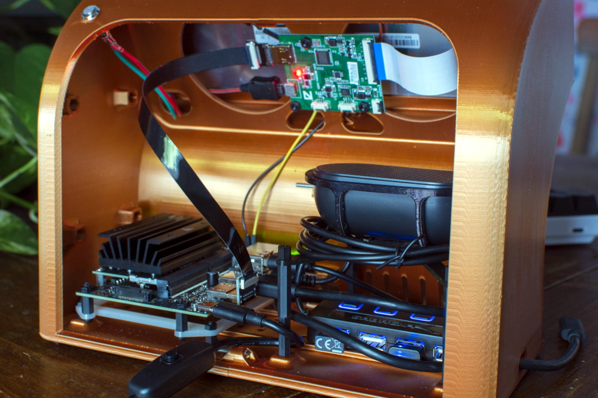
But [Oriol Ferrer Mesià] wonders if we couldn’t improve on things a bit. Over the last few months, he’s been experimenting with small 3D printed enclosures that reimagine the traditional desktop computer aesthetic. With their distinctively retro-futuristic style, they look like the kind of gadgets science magazines in the 1960s thought would be dotting kitchens, living rooms, and space stations by the year 2000. But unlike those fanciful creations, each one of these beauties is a fully functional computer.

A few of the designs are relatively conservative, and not entirely unlike some of the old “dumb terminals” of the 1970s. With a Raspberry Pi 4 and a tablet-sized screen, these diminutive terminals would be perfectly usable for light desktop work or some retro gaming.

But we particularly like the ultra-widescreen design that [Oriol] has come up with. With a fairly unusual 4:1 aspect ratio LCD, the printed enclosure for this one was so large that it had to be done in two pieces on his Ender 3. To keep the 8″ 1920 x 480 panel well fed, this design uses a Jetson Nano 2GB which has considerably more graphical punch than other Linux SBCs of similar size and price.

As part of the recent cyberdeck craze, we’ve seen plenty of people recreating the look and feel of vintage portable computers with 3D printed cases and modern components. Desktop creations have been far less common, but with gorgeous designs like these to serve as inspiration, that may change.

source https://hackaday.com/2021/01/11/retro-terminals-bring-some-style-to-your-desktop/

Circuit Sculpture Vibration Sensor

Here’s your useful and beautiful circuit for the day — [New Pew]’s vibration sensor takes manual control of the flip-flop inside a 555 timer and lights an LED in response. Use it to detect those vibrations you expect, like laundry machines, or those you only suspect, like the kind that might be coming from your engine. This gadget isn’t super-precise, but it will probably get the job done.

The vibration-detecting bit is a tiny ball bearing soldered to the spring from an old pen, which is tied between the trigger and ground pins of the 555. When the chip is powered with a 9 V battery, nearby vibrations will induce wiggle in the spring, causing the ball bearing to contact the brass rod and completing the circuit. When this happens, the internal flip flop’s output goes high, which turns on the LED. Then the flip flop must be reset with a momentary button. Check out the build video after the break.

Want to pick up Earthly vibrations? You can detect earthquakes with a homemade variable capacitor, a 555, and a Raspberry Pi.

source https://hackaday.com/2021/01/10/circuit-sculpture-vibration-sensor/

Hackaday Links: January 10, 2021

You know that feeling when your previously niche hobby goes mainstream, and suddenly you’re not interested in it anymore because it was once quirky and weird but now it’s trendy and all the newcomers are going to come in and ruin it? That just happened to retrocomputing. The article is pretty standard New York Times fare, and gives a bit of attention to the usual suspects of retrocomputing, like Amiga, Atari, and the Holy Grail search for an original Apple I. There’s little technically interesting in it, but we figured that we should probably note it since prices for retrocomputing gear are likely to go up soon. Buy ’em while you can.

Remember the video of the dancing Boston Dynamics robots? We actually had intended to cover that in Links last week, but Editor-in-Chief Mike Szczys beat us to the punch, in an article that garnered a host of surprisingly negative comments. Yes, we understand that this was just showboating, and that the robots were just following a set of preprogrammed routines. Some commenters derided that as not dancing, which we find confusing since human dancing is just following preprogrammed routines. Nevertheless, IEEE Spectrum had an interview this week with Boston Dynamics’ VP of Engineering talking about how the robot dance was put together. There’s a fair amount of doublespeak and couched terms, likely to protect BD’s intellectual property, but it’s still an interesting read. The take-home message is that despite some commenters’ assertions, the routines were apparently not just motion-captured from human dancers, but put together from a suite of moves Atlas, Spot, and Handle had already been trained on. That and the fact that BD worked with a human choreographer to work out the routines.

Looks like 2021 is already trying to give 2020 a run for its money, at least in the marketplace of crazy ideas. The story, released in Guitar World of all places, goes that some conspiracy-minded people in Italy started sharing around a schematic of what they purported to be the “5G chip” that’s supposedly included in the SARS-CoV-2 vaccine. The reason Guitar World picked it up is that eagle-eyed guitar gear collectors noticed that the schematic was actually that of the Boss MetalZone-2 effects pedal, complete with a section labeled “5G Freq.” That was apparently enough to trigger someone, and to ignore the op-amps, potentiometers, and 1/4″ phone jacks on the rest of the schematic. All of which would certainly smart going into the arm, no doubt, but seriously, if it could make us shred like this, we wouldn’t mind getting shot up with it.

Remember the first time you saw a Kindle with an e-ink display? The thing was amazing — the clarity and fine detail of the characters were unlike anything possible with an LCD or CRT display, and the fact that the display stayed on while the reader was off was a little mind-blowing at the time. Since then, e-ink technology has come considerably down market, commoditized to the point where they can be used for price tags on store shelves. But now it looks like they’re scaling up to desktop display sizes, with the announcement of a 25.3″ desktop e-ink monitor by Dasung. Dubbed the Paperlike 253, the 3200 x 1800 pixel display will be able to show 16 shades of gray with no backlighting. The videos of the monitor in action are pretty low resolution, so it’s hard to say what the refresh rate will be, but given the technology it’s going to be limited. This might be a great option as a second or third monitor for those who can work with the low refresh rate and don’t want an LCD monitor backlight blasting them in the face all day.

And finally, if it feels like time has been flying lately, you’re right. The Earth’s rotation on its axis has been shortening lately, such that days are spinning by not in a glacial 24 hours, but at a frenetic pace of 23 hours, 59 minutes, and 59.9998927 seconds. Laugh if you will, but those microseconds add up over the year. Leap seconds have been applied at least 27 times in the last 50 years to correct for Earth’s slowing rotation, but we’re now in a regime that may require a “negative leap second” be applied. Scientists will be studying the trends in Earth’s rotation and make a decision at the World Radiocommunication Conference in 2023, so our 24-hour day is safe until then.

source https://hackaday.com/2021/01/10/hackaday-links-january-10-2021/

Cyberpunk Mazda MX-5 Packs Onboard Cyberdeck

Back in April of 2019, inspired by iconic films such as Blade Runner and Akira, [Chris Watson] embarked on a journey to create his very own cyberpunk roadster from a 1991 Mazda MX-5. After pouring an incredible amount of blood, sweat, and fiberglass into the project, he now has a vehicle that wouldn’t look out of place cruising the streets of Neo Tokyo. Even if you’re not usually into car mods, his impeccably photographed build log is an absolutely fascinating journey.

But as impressive as the car itself might be, what really caught our attention was the computer sitting on the dash. From early on, [Chris] wanted the vehicle to have a companion cyberdeck that would be used to control various onboard systems. At this point it’s just for show, but he says ultimately it will be integrated with the electric motor he plans to install in place of the MX-5’s original power plant. We can’t wait to see it.

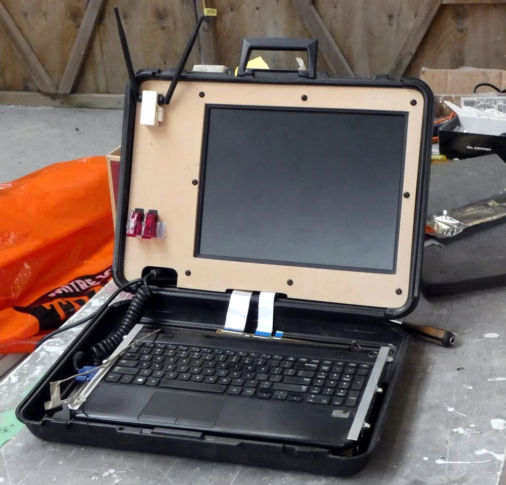
Of course, the lack of a practical application has hardly stopped us from admiring any of the other cyberdecks we’ve covered thus far. This one started out life as a laptop with a broken screen, which [Chris] beheaded and connected it to 15″ external display mounted in the top of a heavy-duty case. With a new SSD and a fresh copy of Linux Mint to verify all the hardware was still functional, he put together an MDF bezel for the display that includes some faux antennae and covered aircraft style switches.

When this futuristic roadster is making an appearance at a car show or contest, [Chris] makes sure to load up some suitably high-tech looking imagery on the display. It even shows some flashing technobabble error messages pulled from The Fast & The Furious.

Traditionally we haven’t covered many custom car projects, though to be fair, we traditionally haven’t seen many that looked like this either. But between ever more technologically advanced vehicles and the insightful car modding column helmed by our very own [Lewin Day], we expect tricked out rides may become an increasingly common sight on these pages.

source https://hackaday.com/2021/01/10/cyberpunk-mazda-mx-5-packs-onboard-cyberdeck/

Turning a Waffle Iron into a Reflow Station

There are a ton of ways to go about building your own reflow oven. Most of these builds start with, well, an oven — usually a toaster oven — with a small but significant minority choosing to modify a hotplate. But this might be the first time we’ve seen a waffle iron turned into a reflow oven.

Of course, what [Vincent Deconinck] came up with is not an oven per se. But his “RefloWaffle” certainly gets the job done. It started with an old waffle maker and a few experiments to see just how much modification it would take to create the various thermal reflow profiles. As it turned out, the original cooking surfaces had too much thermal inertia, so [Vincent] replaced them with plain copper sheets. That made for quicker temperature transitions, plus created some space between the upper and lower heating elements for the SMD board.

As for control, [Vincent] originally used an Arduino with a relay and a thermocouple, but he eventually built a version 2.0 that used a hacked Sonoff as both controller and switch. Adding the thermocouple driver board inside the Sonoff case took a little finagling, but he managed to get everything safely tucked inside. A web interface runs on the Sonoff and controls the reflow process.

We think this is a great build, one that will no doubt see us trolling the thrift stores for cheap waffle irons to convert. We’ve seen some amazing toaster oven reflows, of course, but something about the simplicity and portability of RefloWaffle just works for us.

source https://hackaday.com/2021/01/10/turning-a-waffle-iron-into-a-reflow-station/

Careful Drilling Keeps Stadia From Listening In

Google’s fledgling Stadia service leverages the Chrome ecosystem to deliver streamed PC games on mobile devices, web browsers, and TVs. While not strictly required, the company even offers a dedicated Stadia controller that connects directly to the streaming servers over its own WiFi connection to reduce overall system latency. Of course, being a Google product, the controller has a tiny microphone that’s always listening in.

[Heikki Juva] didn’t like the privacy implications of this, but unfortunately, there appears to be no way to turn off this “feature” in software. He decided the most expedient solution would be to simply remove the microphone from the controller, but it turns out there was a problem. By researching previous teardowns, he found out that it’s nearly impossible to take the controller apart without damaging it.

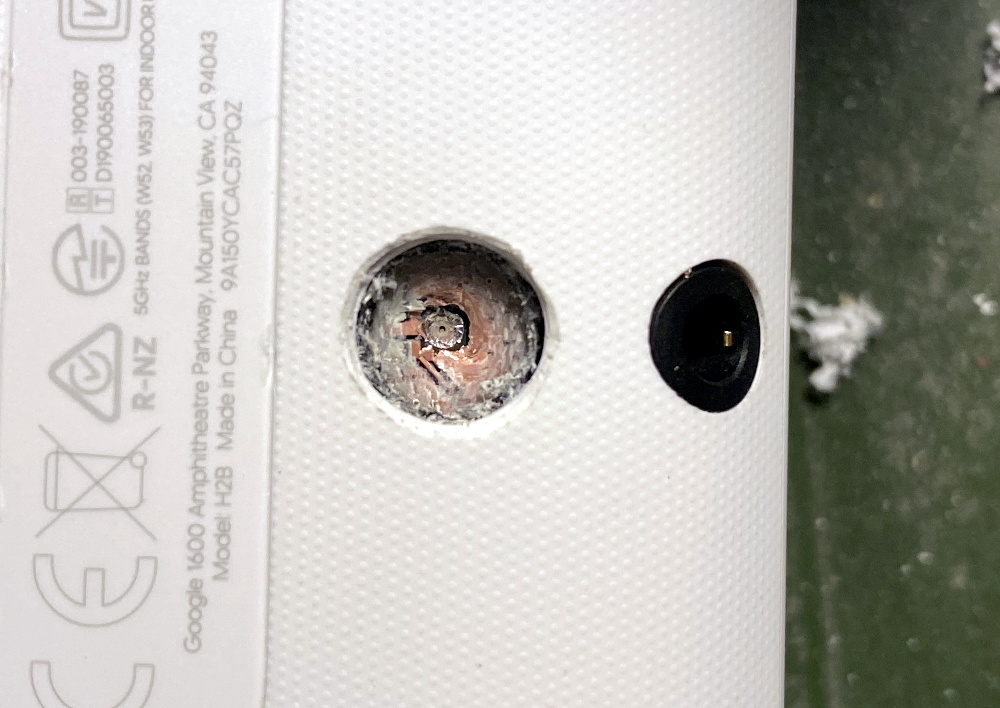
Getting close to the target.

So [Heikki] came up with a bold idea. Knowing roughly the position of the microphone, he would simply drill through the controller’s case to expose and ultimately remove the device. The operation was complicated by the fact that, from the teardown video he saw, he knew he’d also have to drill through the PCB to get to the microphone mounted to the opposite side. The only bright spot was that the microphone was on its own separate PCB, so physically destroying it probably wouldn’t take the whole controller out with it.

Now we don’t have to explain why drilling into a gadget powered by an internal lithium-ion battery is dangerous, and we’re not necessarily vouching for the technique [Heikki] used here. But when presented with a sealed unit like this, we admit there weren’t a lot of good options. The fact that the user should have to go to such ridiculous lengths to disable the microphone in a game controller is a perfect example of why we should try to avoid these adversarially designed devices, but that’s a discussion for another time.

In the end, with a steady and and increasingly larger bits, [Heikki] was able to put a 7 mm hole in the back of the Stadia controller that allowed him to extract the microphone in one piece. Removing the microphone seems to have had no adverse effect on the device as, surprisingly enough, it turns out that a game controller doesn’t actually need to listen to the player. Who knew?

As our devices get smarter, hidden microphones and cameras are unfortunately becoming more common. Thankfully a few manufacturers out there are taking the hint and including hardware kill switches for these intrusive features, but until that becomes the norm, hackers will have to come up with their own solutions.

source https://hackaday.com/2021/01/10/careful-drilling-keeps-stadia-from-listening-in/

Careful Drilling Keeps Stadia From Listening In

Google’s fledgling Stadia service leverages the Chrome ecosystem to deliver streamed PC games on mobile devices, web browsers, and TVs. While not strictly required, the company even offers a dedicated Stadia controller that connects directly to the streaming servers over its own WiFi connection to reduce overall system latency. Of course, being a Google product, the controller has a tiny microphone that’s always listening in.

[Heikki Juva] didn’t like the privacy implications of this, but unfortunately, there appears to be no way to turn off this “feature” in software. He decided the most expedient solution would be to simply remove the microphone from the controller, but it turns out there was a problem. By researching previous teardowns, he found out that it’s nearly impossible to take the controller apart without damaging it.

Getting close to the target.

So [Heikki] came up with a bold idea. Knowing roughly the position of the microphone, he would simply drill through the controller’s case to expose and ultimately remove the device. The operation was complicated by the fact that, from the teardown video he saw, he knew he’d also have to drill through the PCB to get to the microphone mounted to the opposite side. The only bright spot was that the microphone was on its own separate PCB, so physically destroying it probably wouldn’t take the whole controller out with it.

Now we don’t have to explain why drilling into a gadget powered by an internal lithium-ion battery is dangerous, and we’re not necessarily vouching for the technique [Heikki] used here. But when presented with a sealed unit like this, we admit there weren’t a lot of good options. The fact that the user should have to go to such ridiculous lengths to disable the microphone in a game controller is a perfect example of why we should try to avoid these adversarially designed devices, but that’s a discussion for another time.

In the end, with a steady and and increasingly larger bits, [Heikki] was able to put a 7 mm hole in the back of the Stadia controller that allowed him to extract the microphone in one piece. Removing the microphone seems to have had no adverse effect on the device as, surprisingly enough, it turns out that a game controller doesn’t actually need to listen to the player. Who knew?

As our devices get smarter, hidden microphones and cameras are unfortunately becoming more common. Thankfully a few manufacturers out there are taking the hint and including hardware kill switches for these intrusive features, but until that becomes the norm, hackers will have to come up with their own solutions.

source https://hackaday.com/2021/01/10/careful-drilling-keeps-stadia-from-listening-in/

Careful Drilling Keeps Stadia From Listening In

Google’s fledgling Stadia service leverages the Chrome ecosystem to deliver streamed PC games on mobile devices, web browsers, and TVs. While not strictly required, the company even offers a dedicated Stadia controller that connects directly to the streaming servers over its own WiFi connection to reduce overall system latency. Of course, being a Google product, the controller has a tiny microphone that’s always listening in.

[Heikki Juva] didn’t like the privacy implications of this, but unfortunately, there appears to be no way to turn off this “feature” in software. He decided the most expedient solution would be to simply remove the microphone from the controller, but it turns out there was a problem. By researching previous teardowns, he found out that it’s nearly impossible to take the controller apart without damaging it.

Getting close to the target.

So [Heikki] came up with a bold idea. Knowing roughly the position of the microphone, he would simply drill through the controller’s case to expose and ultimately remove the device. The operation was complicated by the fact that, from the teardown video he saw, he knew he’d also have to drill through the PCB to get to the microphone mounted to the opposite side. The only bright spot was that the microphone was on its own separate PCB, so physically destroying it probably wouldn’t take the whole controller out with it.

Now we don’t have to explain why drilling into a gadget powered by an internal lithium-ion battery is dangerous, and we’re not necessarily vouching for the technique [Heikki] used here. But when presented with a sealed unit like this, we admit there weren’t a lot of good options. The fact that the user should have to go to such ridiculous lengths to disable the microphone in a game controller is a perfect example of why we should try to avoid these adversarially designed devices, but that’s a discussion for another time.

In the end, with a steady and and increasingly larger bits, [Heikki] was able to put a 7 mm hole in the back of the Stadia controller that allowed him to extract the microphone in one piece. Removing the microphone seems to have had no adverse effect on the device as, surprisingly enough, it turns out that a game controller doesn’t actually need to listen to the player. Who knew?

As our devices get smarter, hidden microphones and cameras are unfortunately becoming more common. Thankfully a few manufacturers out there are taking the hint and including hardware kill switches for these intrusive features, but until that becomes the norm, hackers will have to come up with their own solutions.

source https://hackaday.com/2021/01/10/careful-drilling-keeps-stadia-from-listening-in/

Lego Heist Bot Steals Keys

Breaking and entering is a felony offense, and one that risks the interloper receiving serious bodily harm for the trouble. Sending in a robot instead is an attractive alternative. While we doubt any actual intention to use their creation for evil, [Brick Experiment Channel] have nonetheless built a viable heist bot out of Lego.

The robot in question is actually two, that work together to execute their mission. Once lowered in the house, the scissor lift bot drives into position next to a coffee table. It then lifts its companion bot into position by extending its motor-driven linear actuators. The recovery bot then drives out onto the table, snatches a set of keys with its arm, and returns to the lift bot, before exiting the house. It’s all achieved with the use of the SBrick, a third-party Lego accessory which allows remote control of Lego motors over Bluetooth. A wireless camera also helps out with vision for the platform.

Lego really does make it easy to build quick, functional mechanisms without a whole lot of fuss. We’ve seen it employed in all sorts of ways, like this handy film scanner. Video after the break.

source https://hackaday.com/2021/01/09/lego-heist-bot-steals-keys/

South Korea Blankets Country with Free WiFi On All Public Transit

Wrapping up a multi-year project to provide free WiFi on all public transportation, South Korea’s Ministry of Science and Information and Communications Technology (MSIT) announced that a total of 35,006 buses had been equipped nationwide.

Previously, subscriber-based WiFi had been installed on subways and in subway stations. It was provided privately by two phone carriers and free only for their subscribers. The coverage was spotty and slow, and in 2017 the government took over and implemented a better system. With this announcement, the whole public transportation system is now covered with stable and free WiFi.

We also noticed that the government has released the details of the 220,000 WiFi access points to the public. This includes the location, IP address, and RSSI data for use by people and companies wanting to develop location-based services. What is the state of free WiFi access points in your region, and does it extend to public transportation? Do you find it reliable, or do you use your data plan when out and about?

source https://hackaday.com/2021/01/09/south-korea-blankets-country-with-free-wifi-on-all-public-transit/

New Part Day: Espressif ESP32-S3

Since Espressif Systems arrived in our collective consciousness they have expanded their range from the ESP8266 to the ESP32, and going beyond the original WROOM and WROVER modules to a range of further ESP32 products. There’s a single-core variant and one that packs a RISC-V core in place of the Tensilica one, and now they’ve revealed their latest product. The ESP32-S3 takes the ESP to a new level, packing as it does more I/O, onboard USB, and an updated version of the two Tensilica cores alongside Bluetooth version 5. It’s still an ESP32, but one that’s more useful, and it’s worth a closer look because we expect it to figure in quite a few projects.

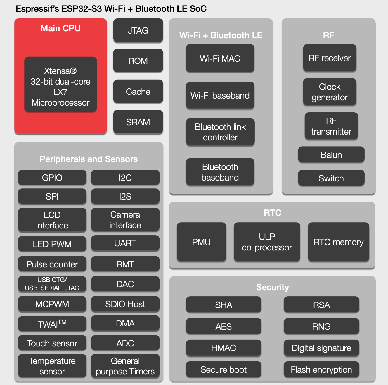
Espressif's block diagram for the chip.
Espressif’s block diagram for the chip.

Sadly the data sheet does not seem to have been released, but we do have some titbits to consider. Espressif are anxious to tell us about its “AIOT” capabilities thanks to the vector instructions in the EXTensa LX7 cores (PDF) that were not present in the previous model’s LX6. They claim that this will speed up software neural networks; this does have an air of marketing about it but we’ll withhold judgement until we see it in use. The new core certainly will offer a performance improvement across the board though, which should be of interest to all ESP32 developers. Meanwhile the ultra-low-power core that existing ESP32 developers will be familiar with remains.

Then there is that USB support, which appears in the feature block diagram but has little information elsewhere. It’s listed as USB OTG which raises the possibility of the ESP32 being the host, but what it should also bring is the ability to emulate other USB devices. We’ve seen badges mount as WebUSB devices using STM32 clones as peripherals for an ESP32, but in future these tricks should be possible on the Espressif chip itself.

Probably the most anticipated piece of the new device’s specification comes in the addition of 10 new I/O lines. This has historically been a weakness of the ESP line, that it’s an easy chip with which to run out of available pins. These extra lines will make it more competitive with for example the STM32 series of microcontrollers that have larger package options, and will also mean that designs can have more in the way of peripherals without the use of port expanders.

In summary then, the latest member of the ESP32 family delivers a significant and useful update, and brings some of the features first seen in the single core version to the more powerful line of chips. Sadly it doesn’t have the hoped-for on-chip RAM boost, but it brings enough in the way of new capabilities to be of interest. At the moment it doesn’t look like the ESP32-S3 is available to order, but we hope to have engineering samples soon and should be bringing you a hands-on report in due course.

source https://hackaday.com/2021/01/09/new-part-day-espressif-esp32-s3/

New Part Day: Espressif ESP32-S3

Since Espressif Systems arrived in our collective consciousness they have expanded their range from the ESP8266 to the ESP32, and going beyond the original WROOM and WROVER modules to a range of further ESP32 products. There’s a single-core variant and one that packs a RISC-V core in place of the Tensilica one, and now they’ve revealed their latest product. The ESP32-S3 takes the ESP to a new level, packing as it does more I/O, onboard USB, and an updated version of the two Tensilica cores alongside Bluetooth version 5. It’s still an ESP32, but one that’s more useful, and it’s worth a closer look because we expect it to figure in quite a few projects.

Espressif's block diagram for the chip.
Espressif’s block diagram for the chip.

Sadly the data sheet does not seem to have been released, but we do have some titbits to consider. Espressif are anxious to tell us about its “AIOT” capabilities thanks to the vector instructions in the EXTensa LX7 cores (PDF) that were not present in the previous model’s LX6. They claim that this will speed up software neural networks; this does have an air of marketing about it but we’ll withhold judgement until we see it in use. The new core certainly will offer a performance improvement across the board though, which should be of interest to all ESP32 developers. Meanwhile the ultra-low-power core that existing ESP32 developers will be familiar with remains.

Then there is that USB support, which appears in the feature block diagram but has little information elsewhere. It’s listed as USB OTG which raises the possibility of the ESP32 being the host, but what it should also bring is the ability to emulate other USB devices. We’ve seen badges mount as WebUSB devices using STM32 clones as peripherals for an ESP32, but in future these tricks should be possible on the Espressif chip itself.

Probably the most anticipated piece of the new device’s specification comes in the addition of 10 new I/O lines. This has historically been a weakness of the ESP line, that it’s an easy chip with which to run out of available pins. These extra lines will make it more competitive with for example the STM32 series of microcontrollers that have larger package options, and will also mean that designs can have more in the way of peripherals without the use of port expanders.

In summary then, the latest member of the ESP32 family delivers a significant and useful update, and brings some of the features first seen in the single core version to the more powerful line of chips. Sadly it doesn’t have the hoped-for on-chip RAM boost, but it brings enough in the way of new capabilities to be of interest. At the moment it doesn’t look like the ESP32-S3 is available to order, but we hope to have engineering samples soon and should be bringing you a hands-on report in due course.

source https://hackaday.com/2021/01/09/new-part-day-espressif-esp32-s3/

New Part Day: Espressif ESP32-S3

Since Espressif Systems arrived in our collective consciousness they have expanded their range from the ESP8266 to the ESP32, and going beyond the original WROOM and WROVER modules to a range of further ESP32 products. There’s a single-core variant and one that packs a RISC-V core in place of the Tensilica one, and now they’ve revealed their latest product. The ESP32-S3 takes the ESP to a new level, packing as it does more I/O, onboard USB, and an updated version of the two Tensilica cores alongside Bluetooth version 5. It’s still an ESP32, but one that’s more useful, and it’s worth a closer look because we expect it to figure in quite a few projects.

Espressif's block diagram for the chip.
Espressif’s block diagram for the chip.

Sadly the data sheet does not seem to have been released, but we do have some titbits to consider. Espressif are anxious to tell us about its “AIOT” capabilities thanks to the vector instructions in the EXTensa LX7 cores (PDF) that were not present in the previous model’s LX6. They claim that this will speed up software neural networks; this does have an air of marketing about it but we’ll withhold judgement until we see it in use. The new core certainly will offer a performance improvement across the board though, which should be of interest to all ESP32 developers. Meanwhile the ultra-low-power core that existing ESP32 developers will be familiar with remains.

Then there is that USB support, which appears in the feature block diagram but has little information elsewhere. It’s listed as USB OTG which raises the possibility of the ESP32 being the host, but what it should also bring is the ability to emulate other USB devices. We’ve seen badges mount as WebUSB devices using STM32 clones as peripherals for an ESP32, but in future these tricks should be possible on the Espressif chip itself.

Probably the most anticipated piece of the new device’s specification comes in the addition of 10 new I/O lines. This has historically been a weakness of the ESP line, that it’s an easy chip with which to run out of available pins. These extra lines will make it more competitive with for example the STM32 series of microcontrollers that have larger package options, and will also mean that designs can have more in the way of peripherals without the use of port expanders.

In summary then, the latest member of the ESP32 family delivers a significant and useful update, and brings some of the features first seen in the single core version to the more powerful line of chips. Sadly it doesn’t have the hoped-for on-chip RAM boost, but it brings enough in the way of new capabilities to be of interest. At the moment it doesn’t look like the ESP32-S3 is available to order, but we hope to have engineering samples soon and should be bringing you a hands-on report in due course.

source https://hackaday.com/2021/01/09/new-part-day-espressif-esp32-s3/

Micromachining Glass with a Laser — Very, Very Slowly

When it comes to machining, the material that springs to mind is likely to be aluminum, steel, or plastic. We don’t necessarily think of glass as a material suitable for machining, at least not in the chuck-it-up-in-the-lathe sense. But glass is a material that needs to be shaped, too, and there are a bunch of different ways to accomplish that. Few, though, are as interesting as micromachining glass with laser-induced plasma bubbles. (Video, embedded below.)

The video below is from [Zachary Tong]. It runs a bit on the longish side, but we found it just chock full of information. The process, formally known as “laser-induced backside wet-etching,” uses a laser to blast away at a tank of copper sulfate. When a piece of glass is suspended on the surface of the solution and the laser is focused through the glass from the top, some interesting things happen.

The first pulse of the laser vaporizes the solution and decomposes the copper sulfate. Copper adsorbs onto the glass surface inside the protective vapor bubble, which lasts long enough for a second laser pulse to come along. That pulse heats up the adsorbed copper and the vapor in the original bubble, enough to melt a tiny bit of the glass. As the process is repeated, small features are slowly etched into the underside of the glass. [Zachary] demonstrates all this in the video, as well as what can go wrong when the settings are a bit off. There’s also some great high-speed footage of the process that’s worth the price of admission alone.

We doubt this process will be a mainstream method anytime soon, not least because it requires a 50-Watt Nd:YAG fiber laser. But it’s an interesting process that reminds us of [Zachary]’s other laser explorations, like using a laser and Kapton to make graphene supercapacitors.

source https://hackaday.com/2021/01/09/micromachining-glass-with-a-laser-very-very-slowly/

Replacement LED light build uses a few tricks

Microscopes have become essential work bench tools for hackers, allowing them to work with tiny SMD parts for PCB assembly and inspection. Couple of years back, mad scientist [smellsofbikes] picked up a stereo microscope from eBay. But its odd-sized, 12 volt Edison-style screw base lamp, connected to a 17 volt AC supply, burned off after a while. He swapped the burnt lamp with the spare, which too blew up after some time. Dumb lamps. Maybe the original spec called for 24 volt lamps, which were unobtanium due to the odd Edison screw base, but those would throw out a pretty yellow-orange glow. Anyhow, for some time, he worked with a jury-rigged goose neck lamp, but frequently moving the microscope and the lamp was becoming a chore. When he got fed up enough about it, he decided to Build a Replacement LED Microscope Light.

Usually, such builds are plain vanilla and not much to write in about, but [smellsofbikes] has a few tricks worth taking note of. He found a couple of high power, SMD LEDs in his parts bin. They were just slightly wider than 1.6 mm across the terminals. So he took a piece of double sided, copper clad FR4, and edge mounted the LED against one side of the PCB piece, twisting it slightly so he could solder both terminals. This works as a great heat sink for the LED while still having a very narrow profile. This was important as the replacement LED board had to fit the cylinder in which the original lamp was fitted.
The LED is driven by a constant current buck regulator, powered by the original 17 volt transformer. A bridge rectifier and several filter capacitors result in a low ripple DC supply, for which he used the KiCad spice functionality to work out the values. The LM3414 driver he used is a bit off the beaten track. It can run LEDs up to 60 watts at 1 amps and does not require an external current sense resistor. This was overkill since he planned to run the LED at just 150 mA, which would result in a very robust, long lasting solution. He designed the driver PCB in KiCad, and milled it on his LPKF circuit board plotter. The nice thing with CNC milled PCBs is that you can add custom copper floods and extend footprint pads. This trick lets you solder either a 0805 or a 1206 part to the same footprint – depending on what you can dig up from your parts bin.

What left us wondering was [smellsofbikes] statement that “The only annoying bit is it (LM3414) also needs to have its enable pin tied high, but the enable pin has a max voltage of 5.5V, so I have to derive 5.5V from the 20-ish volts of the rectified transformer voltage.” Looking at the LM3414 datasheet, there is a VCC output on pin 1, derived from an internal regulator. From the data sheet, “The VCC provides self bias for the internal gate drive and control circuits.” We are not sure why this could not be used to tie the Enable (actually the PWM pin) to 5 volts without having to use an external regulator. Instead, he added a SOT-23 regulator in his design to get the 5 volt to enable the driver. But the regulator he had on hand had an odd, inverted pin out, and had to dead-bug solder the SOT-23 LDO to make it work. Eventually, it all worked out great, so we guess all’s well that ends well.

To fit the LED PCB in side the original cylinder, he designed a 3D printed collar with tapered fingers which hold the PCB without having to use any fasteners. For the main PCB, a simple 3D printed housing was used to fit it inside the transformer box. Even at 150 mA drive current, the LED lamp is mighty bright, and the over-kill driver will make sure he doesn’t have to worry about a burnt out lamp any time soon.

source https://hackaday.com/2021/01/08/replacement-led-light-build-uses-a-few-tricks/

Helping Hands, Reinvented

[Nixie] was tired of using whatever happens to be around to hold things in place while soldering and testing. It was high time to obtain a helping hands of some kind, but [Nixie] was dismayed by commercial offerings — the plain old alligator clips and cast metal type leave a lot to be desired, and the cooling tube cephalopod type usually have the alligator clips just jammed into the standard tube ends with no thought given to fine control or the possibility of reducing cable count.

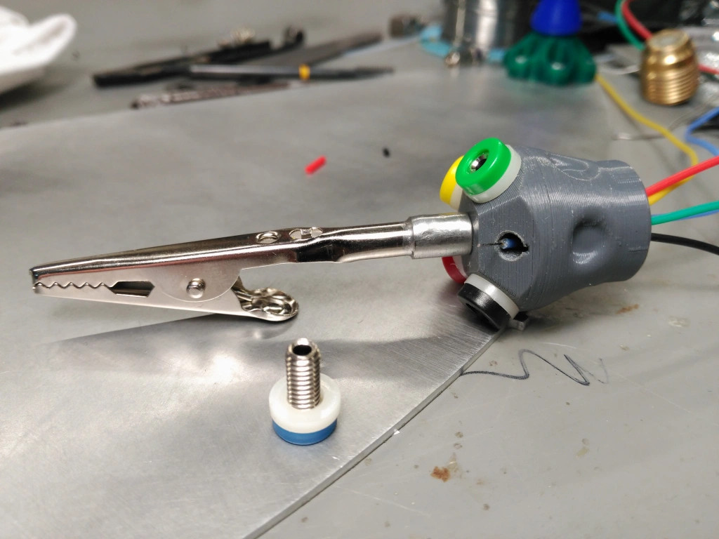
[Nixie] happened to have some unneeded cooling tube lying around and started designing a new type of helping hands from the ground plane up. Taking advantage of the fact that cooling tubes are hollow,  [Nixie] routed silicone-jacketed wires through them for power and low speed signals. These are soldered to five banana jacks that are evenly spaced around an alligator clip.

Even if you don’t need power, all those extra alligators would come in quite handy for circuit sculpture or anything else that requires a lot of hands. [Nixie] put the files up on Thingiverse if you want to make your own.

We’ve seen plenty of helping hands over the years, but this concrete-based helper ought to cement your decision to make your own.

source https://hackaday.com/2021/01/08/helping-hands-reinvented/

Helping Hands, Reinvented

[Nixie] was tired of using whatever happens to be around to hold things in place while soldering and testing. It was high time to obtain a helping hands of some kind, but [Nixie] was dismayed by commercial offerings — the plain old alligator clips and cast metal type leave a lot to be desired, and the cooling tube cephalopod type usually have the alligator clips just jammed into the standard tube ends with no thought given to fine control or the possibility of reducing cable count.

[Nixie] happened to have some unneeded cooling tube lying around and started designing a new type of helping hands from the ground plane up. Taking advantage of the fact that cooling tubes are hollow,  [Nixie] routed silicone-jacketed wires through them for power and low speed signals. These are soldered to five banana jacks that are evenly spaced around an alligator clip.

Even if you don’t need power, all those extra alligators would come in quite handy for circuit sculpture or anything else that requires a lot of hands. [Nixie] put the files up on Thingiverse if you want to make your own.

We’ve seen plenty of helping hands over the years, but this concrete-based helper ought to cement your decision to make your own.

source https://hackaday.com/2021/01/08/helping-hands-reinvented/

Helping Hands, Reinvented

[Nixie] was tired of using whatever happens to be around to hold things in place while soldering and testing. It was high time to obtain a helping hands of some kind, but [Nixie] was dismayed by commercial offerings — the plain old alligator clips and cast metal type leave a lot to be desired, and the cooling tube cephalopod type usually have the alligator clips just jammed into the standard tube ends with no thought given to fine control or the possibility of reducing cable count.

[Nixie] happened to have some unneeded cooling tube lying around and started designing a new type of helping hands from the ground plane up. Taking advantage of the fact that cooling tubes are hollow,  [Nixie] routed silicone-jacketed wires through them for power and low speed signals. These are soldered to five banana jacks that are evenly spaced around an alligator clip.

Even if you don’t need power, all those extra alligators would come in quite handy for circuit sculpture or anything else that requires a lot of hands. [Nixie] put the files up on Thingiverse if you want to make your own.

We’ve seen plenty of helping hands over the years, but this concrete-based helper ought to cement your decision to make your own.

source https://hackaday.com/2021/01/08/helping-hands-reinvented/

Old Kindle Shows HDMI Video, Eventually

Even with the recent price reductions on stand-alone panels, picking up a used Kindle is still arguably the most cost effective way to get your hands on a large electronic paper display. Especially when you consider the Kindle includes a battery, case, and electronics to drive the display. Bending the Kindle software to your whims introduces its own unique challenges of course, but with a little tweaking, an old e-reader can live again as whatever you wish it to be.

Case in point, the OkMonitor project by [Brendan Sleight]. Using a somewhat dizzying combination of software and hardware, he’s figured out a way to turn an older Kindle Paperwhite into a plug-and-play HDMI monitor. Is it a great monitor? Far from it. As the name implies, the best you can hope to get from this solution is an OK monitor. But at least it’s something.

There’s quite a bit going on behind the scenes in OkMonitor, which [Brendan] describes through a slideshow on the project page. But the high-level idea is that a Raspberry Pi 4 with a simple USB HDMI capture device takes the video input and converts it on the fly to a scaled down Kindle-friendly format. The converted video is streamed over WiFi to the jailbroken Kindle with netcat, where it’s displayed by a native video player. In the video after the break you can see that the end result looks pretty impressive, even if there is a considerable delay involved.

Despite the demonstration [Brendan] has put together for OkMonitor, we can’t say we’d watch many films over this setup. But the fact that you can plug any HDMI device into the “base station” and have the video sent out to one or more Kindles is undeniably impressive. It’s definitely worth a close look, even if you just take some of the concepts of this project to get your own Kindle repurposing idea off the ground.

We’ve recently seen some promising progress made towards repurposing large e-paper price tags labels, but it’s hard to imagine such niche devices will ever become cheaper than second hand Kindles. With continued software development, these old e-readers are likely to remain quite popular among hackers.

source https://hackaday.com/2021/01/08/old-kindle-shows-hdmi-video-eventually/

Hackaday Podcast 100: Arduino Plays CDs, Virtual Reality in the 60s, and Magical Linear Actuators

Hackaday editors Elliot Williams and Mike Szczys kick off the first episode of the new year with the best hacks the internet has to offer. There’s a deep dive into water-level sensing using a Christmas tree as an excuse. We ooh and ah over turning a CD-ROM drive into a CD player (miraculous tech of the previous century?). Do you have any use cases for ATtiny oscillator calibration registers? We look in on a hack that makes it dead simple to measure and set their values. The episode finishes up with a discussion of the constantly moving goal posts of virtual reality.

Take a look at the links below if you want to follow along, and as always, tell us what you think about this episode in the comments!

Direct download (~65 MB)

Places to follow Hackaday podcasts:

Episode 100 Show Notes:

New This Week:

  • Elliot’s been rebuilding his CNC foam cutter
  • Mike’s getting closer to a proper automated backup system

Interesting Hacks of the Week:

Quick Hacks:

Can’t-Miss Articles:

source https://hackaday.com/2021/01/08/hackaday-podcast-100-arduino-plays-cds-virtual-reality-in-the-60s-and-magical-linear-actuators/

Solid Oak Arcade Cabinet: When Particle Board Won’t Do

Having an arcade cabinet of one’s own is a common dream among those who grew up during the video game arcade heyday of the 80s and early 90s. It’s a fairly common build that doesn’t take too much specialized knowledge to build. This cabinet, on the other hand, pulled out all of the stops for the cabinet itself, demonstrating an impressive level of woodworking expertise.

The cabinet enclosure is made with red oak boards, which the creator [Obstreperuss] sawed and planed and then glued together to create the various panels (more details are available on his Imgur album). The Mario artwork on the sides and front aren’t just vinyl stickers, either. He used various hardwoods cut into small squares to create pixel art inlays in the oak faces. After the fancy woodwork was completed, the build was finished out with some USB arcade controllers, a flat-panel screen, and a Raspberry Pi to run the games.

While the internals are pretty standard, we have to commend the incredible quality of the woodworking. It’s an impressive homage to classic arcade machines and we wouldn’t mind a similar one in our own homes. If you’re lacking the woodworking equipment, though, it’s possible to get a refined (yet smaller) arcade cabinet for yourself with a 3D printer instead.

source https://hackaday.com/2021/01/08/solid-oak-arcade-cabinet-when-particle-board-wont-do/