Do you have a great application for computer vision, but couldn’t spare the cost of hardware needed to build it? Or perhaps you just need a deadline to pull you away from endless doom scrolling? Either way, the OpenCV team wants you to enter their OpenCV AI Competition 2021 and they’re willing to pitch in hardware to make it happen.
This competition is part of OpenCV’s 20th anniversary celebration, and the field of machine vision has changed a lot in those two decades. OpenCV started within Intel harnessing power of their high end CPUs, but today the excitement is around specialized acceleration hardware for vision processing. Which is why OpenCV put their support and lent their name to the OpenCV AI Kit (OAK) Kickstarter we covered a few months ago. Since then, the hardware was produced and starting to arrive in project backer’s hands. (Barring pandemic-related shipping restrictions…)
This shiny new hardware is the competition’s focus. Phase one solicits team proposals for putting an OAK-D’s power to novel use. University teams may have up to ten members, general teams are limited to four. Each team’s geographic home will put them in one of six global regions. Proposals must be submitted by January 27th, 2021. By February 11th, judges will select the best twenty-five general and ten university team proposals from each region, and every member of the team gets an OAK-D unit to turn their idea into reality by phase two deadline of June 27th. That’s up to 1,200 OAK-D modules available to anyone who can convince the judges they have a great idea and they are capable of bringing it to fruition. Is that you? Of course it is!
Teams will also receive additional resources such as an allotment of cloud compute credits to train their models, and naturally all tutorials and sample code released as part of OAK Kickstarter. No explicit resource for project team organization is mentioned, but of course our own Hackaday.io is available to support you. Best of luck to everyone who enters and we look forward to seeing all the projects this contest will bring to life.
You’ve got a machine hooked up to the Internet via a shiny new cellular modem, which you plan to administer remotely. You do a quick check on the external IP, and try and log in from another PC. Try as you might, SSH simply won’t connect. What gives?
The reality of the modern internet is that most clients no longer get their own unique IPv4 address. There simply aren’t enough to go around anymore. Instead, most telecommunications operators use Carrier Grade Network Address Translation which allows a single external address to be shared by many customers. This can get in the way of direct connection attempts from the outside world. Even if that’s not the case, most cellular operators tend to block inbound connections by default. However, there is a way around this quandary – using a VPN.
A Network That’s Private And Virtual
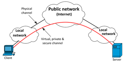
A VPN allows two or more systems connected to the Internet to behave as if they’re on a local network. This is useful for remote administration, particularly when working with cellular connections with restrictive traffic rules.
VPNs, or Virtual Private Networks, are exactly what they sound like. They’re a private network that exists between clients on a broader public network like the Internet. When it comes to making connections to remote hosts on cellular connections, they’re the perfect tool to get the job done. Having the remote host connect to a VPN server gets around the issue of rejected incoming connections, as all traffic goes through the VPN tunnel initiated by the remote host itself. Additionally, it means that other hosts connected to the VPN can talk to the remote host as if it’s another machine on a local network. With the correct setup, a VPN can be a highly secure and flexible way of talking to remote machines with a minimum of fuss and bluster.
You can run your own VPN server at home without much trouble. You’ll need a computer with reliable Internet access, that can accept incoming connections. Typically, this will involve enabling port forwarding on your home router so that connections made to your home IP on a particular port are forwarded to the computer running the VPN server software. Additionally, you’ll need to make sure your home internet connection isn’t behind carrier-grade NAT. Generally, if you’ve got cable, ADSL, or fiber, a simple phone call to your ISP is all that’s required. However, in some cases, you may find you have to upgrade to a higher tier connection package to get such treatment. There’s no need to have a static IP, either; dynamic DNS services can make it easy for your remote system to call back home. You can even run your own Dynamic DNS if you so desire.
So, assuming you’ve got a computer standing by, and a router with an open port to the wider internet, all you need to do is install the right software. OpenVPN is a popular choice for running a VPN server, and has all the functionality required with a bonus of being free. Historically, it’s required a significant amount of setup to install and generate all the required cryptographic certificates, however, with the release of OpenVPN Access Server, getting started is somewhat more streamlined.
Other options exist, however. PageKite is an opensource VPN solution that aims to make connecting remote systems a cinch. We’ve featured it before when discussing how to connect to Raspberry Pis from anywhere and everywhere. It’s available on a pay-what-you-want basis, with some data going through PageKite’s cloud servers to make everything that much easier to setup. Recommended pricing is just $3 USD a month, rising to $6 USD a month for more serious users. It’s a great way to get started if you just need to get your remote system talking online without a lot of unnecessary yak shaving. Another solution is WireGuard, an open-source VPN built upon concepts of ease-of-use, speed, and simplicity. With clients available for a broad base of popular operating systems, it’s easy to get up and running without a whole lot of fuss.
Once you’ve got your remote host connecting to a VPN, admin is easy. Simply enable SSH or your favored remote admin protocol, and log in as if the machine were on your local network. If your remote machine is properly configured to maintain the connection and reconnect on dropouts, you should have no issues controlling the machine no matter where it finds itself in the world – as long as it’s got a good cellular data connection. Just make sure that before you deploy it to a far flung locale, you have it to connect to the VPN on boot – else you’ll be out of luck the first time you need to command a restart.
If you’ve been following this series, you should now be confident to select the right hardware and software to control a computer remotely over the cellular network. Of course, with the roaming freedom of cellular network comes the difficulty that your remote system may end up somewhere far away and difficult to access. In the event something goes wrong, this can make solving the problem expensive and complicated. In future articles, we’ll explore ways to minimise these problems and how to best stop things from going sideways. Until then, happy hacking!
Humanoid robots always attract attention, but anyone who tries to build one quickly learns respect for a form factor we take for granted because we were born with it. Pollen Robotics wants to help move the field forward with Reachy: a robot platform available both as a product and as a wealth of information shared online.
This French team has released open source robots before. We’ve looked at their Poppy robot and see a strong family resemblance with Reachy. Poppy was a very ambitious design with both arms and legs, but it could only ever walk with assistance. In contrast Reachy focuses on just the upper body. One of the most interesting innovations is found in Reachy’s neck, a cleverly designed 3 DOF mechanism they called Orbita. Combined with two moving antennae at the top of the head, Reachy can emote a wide range of expressions despite not having much of a face. The remainder of Reachy’s joints are articulated with Dynamixel serial bus servos though we see an optional Orbita-based hand attachment in the demo video (embedded below).
Reachy’s € 19,990 price tag may be affordable relative to industrial robots, but it’s pretty steep for the home hacker. No need to fret, those of us with smaller bank accounts can still join the fun because Pollen Robotics has open sourced a lot of Reachy details. Digging into this information, we see Reachy has a Google Coral for accelerating TensorFlow and a Raspberry Pi 4 for general computation. Mechanical designs are released via web-based Onshape CAD. Reachy’s software suite on GitHub is primarily focused on Python, which allows us to experiment within a Jupyter notebook. Simulation can be done within Unity 3D game engine, which can be optionally compiled to run in a browser like the simulation playground. But academic robotics researchers are not excluded from the fun, as ROS1 integration is also available though ROS2 support is still on the to-do list.
Reachy might not be as sophisticated as some humanoid designs we’ve seen, and without a lower body there’s no way for it to dance. But we are very appreciative of a company willing to share knowledge with the world. May it spark new ideas for the future.
It’s often said that any sufficiently advanced technology is indistinguishable from magic, and when a DIY device lets you light up fluorescent bulbs with a flick of the wrist, it’s certainly not hard to see why. The latest creation from [Jay Bowles], this high voltage wand is actually a Slayer Exciter coil that’s able to boost the output of a standard 9 V alkaline or rechargeable battery high enough to perform some of the wireless power tricks we usually associate with the more complex Tesla coil.
We really can’t overstate how simple it is to build one of these yourself. Sure you’ll still need to wind the coil, but if you can chuck the 1/2 inch acrylic tube into a electric drill you should be able to make short work of it. Once you’ve wound your secondary coil from 32 gauge magnet wire, you only need a couple turns of common doorbell wire to make up the primary.
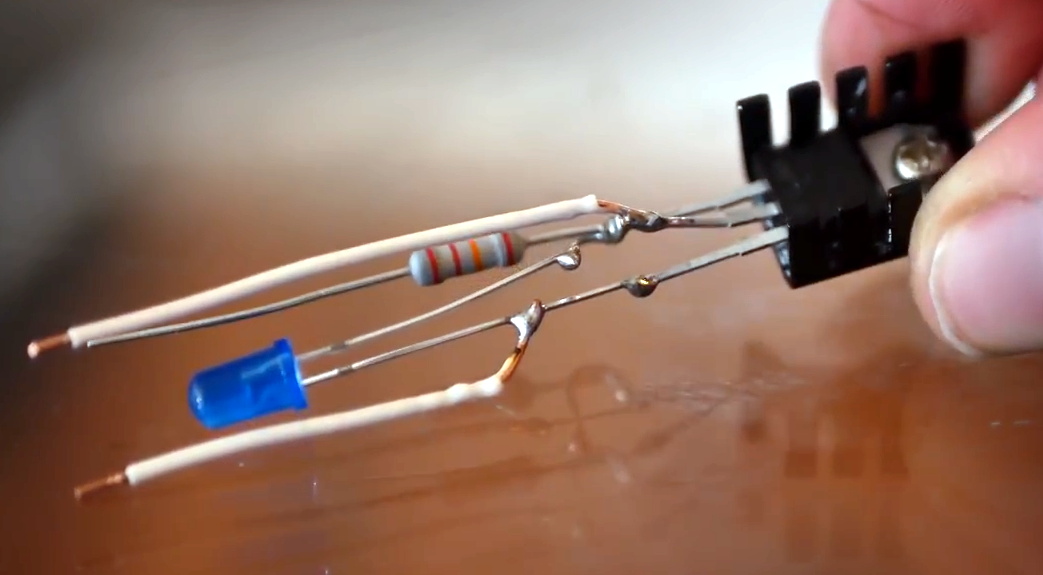
Think there must be some complex electronics hiding in the handle? Far from it. All that’s hidden by that faux-leather wrapping is a transistor to do the high-speed switching, an LED functioning as both the power indicator and the circuit’s diode, and a resistor. [Jay] put it all together dead bug style, but you could do it on a scrap of perfboard if you’d like something a little more robust.
Being a big believer in STEM education, [Jay] says the wand was designed to be as kid-friendly as possible so he could gift it to his young niece and nephew. Inspiring the next generation is certainly something we respect around these parts, though we think there’s plenty of adults who wouldn’t have been disappointed if they unwrapped a gadget like this over the holidays.
It’s often said that any sufficiently advanced technology is indistinguishable from magic, and when a DIY device lets you light up fluorescent bulbs with a flick of the wrist, it’s certainly not hard to see why. The latest creation from [Jay Bowles], this high voltage wand is actually a Slayer Exciter coil that’s able to boost the output of a standard 9 V alkaline or rechargeable battery high enough to perform some of the wireless power tricks we usually associate with the more complex Tesla coil.
We really can’t overstate how simple it is to build one of these yourself. Sure you’ll still need to wind the coil, but if you can chuck the 1/2 inch acrylic tube into a electric drill you should be able to make short work of it. Once you’ve wound your secondary coil from 32 gauge magnet wire, you only need a couple turns of common doorbell wire to make up the primary.
Think there must be some complex electronics hiding in the handle? Far from it. All that’s hidden by that faux-leather wrapping is a transistor to do the high-speed switching, an LED functioning as both the power indicator and the circuit’s diode, and a resistor. [Jay] put it all together dead bug style, but you could do it on a scrap of perfboard if you’d like something a little more robust.
Being a big believer in STEM education, [Jay] says the wand was designed to be as kid-friendly as possible so he could gift it to his young niece and nephew. Inspiring the next generation is certainly something we respect around these parts, though we think there’s plenty of adults who wouldn’t have been disappointed if they unwrapped a gadget like this over the holidays.
The availability of inexpensive electronics modules has opened up a world of opportunity for more complex projects to be completed quickly. Rather than designing everything from scratch, ready-made motor modules, regulators, computer vision modules, and control modules all ready to be put to work after arriving at one’s doorstep. Sometimes, though, these inexpensive electronics aren’t all they’re cracked up to be, so [Jan] decided to produce them from scratch instead.
[Jan] is the creator of several robots, and frequently makes use of 3.3V and 5V step down modules, but was not happy with the consistency offered by the prefab modules. The solution to this was to build them from scratch in a way that makes producing a large amount nearly as easy as ordering them. The boards are based around the SY8105 chip, and are built in two batches for the robotics shop based on the two most commonly needed output voltages. With their design they get exactly what they need every time, without worrying about reliability from a random board shop overseas.
The robotics shop is called RoboticsBrno and they have made the schematics available for anyone that wants to build their own. That being said, the design does not make considerations for low noise since it isn’t required for their use case, but if you’d prefer something simple and reliable this will get the job done. It’s also important to understand the limitations of the parts in a build that are built by a third party, although power supplies are a pretty common area to make improvements on.
When 3D pens first became available, many assumed them to be gimmicky or part of a general fad that would eventually die out. Like most revolutionary technologies, though, they’ve found a firm foothold, especially in the art community where the ability to 3D print in freehand is incredibly valuable. There are still some shortcomings with the technology, though, but [tterev3] recently tore into a 3doodler pen to make some necessary upgrades.
First, this pen has some design choices that are curious, to say the least. The cooling fan runs regardless of temperature, and it has pushbuttons for start and stop rather than a momentary button that controls the extrusion. To fix these issues, as well as change the filament size, improve the cooling, and provide greater control over the extrusion speed, [tterev3] completely rewrote the firmware, changed the microcontroller on the PCB, and made several hardware upgrades to accommodate these changes. He also went ahead and installed a USB-C port for charging, which should be standard practice on all low-voltage consumer electronics by now anyway.
The detail work on this project is impressive, given the small size of the pen itself and the amount of precision hardware needed to make the changes. Especially regarding the replacement of the microcontroller on the board itself, which is an impressive feat even without the incredibly small dimensions. The firmware upgrade is available on his GitHub page as well if you have your own 3doodler that needs modifications, and if you’re still struggling to find uses for these handy devices, we’ve seen them used with interesting effect to build drones.
LED matrixes were once a total headache, requiring careful consideration to make the most of limited I/O pins and available microcontroller resources. These days, addressable LED strings have made it all a cinch. Thus, going a little out of the box isn’t so daunting. [w.r.simpson] did just that with this hex-matrix clock.
Relying on hexes instead of a normal Cartesian grid requires some attention to how the rows and columns are laid out, but the Instructable goes through the necessary coordinate system to address the display. The whole display was built without a 3D printer, instead relying on some basic craft skills and a picture frame as the enclosure. Strips of WS2812B LEDs were used to build the hexagonal matrix, run by a Adafruit Metro Mini 328. To give each hexagonal pixel, or hexel, a crisp outline, a shadow grid was built using black paper to stop the light bleeding between the display segments when switched on. Smoked plexiglas wasn’t available, so instead, tinted window film was used to darken the front of the display.
The result is impressive; while some glue marks from the shadow grid are visible closeup, from a distance the final product looks incredibly futuristic thanks to the hexagonal layout. We can imagine this would make a great set dressing in a futuristic film clip; we fully expect to see this concept in the background of the next Ariana Grande single. If this build isn’t enough six-sided fun to sate your appetite, consider getting into Super Hexagon too!
Sand plotters are beautiful machines. They can make endless patterns, over and over again, only to wipe away their own creation with each new pass. Having seen the famous Sisyphus sand sculpture online, [Simon] decided to make his own.
The build came together quickly, thanks to [Simon]’s well-stocked workshop and experience with CNC motion platforms. The frame was built out of wood, with a combination of hand-cut and lasercut parts. After fabric-wrapping the outer rim turned out poorly, rope was substituted instead for a stylish, organic look. LEDs were installed inside to light the sand for attractive effect. The metal ball is moved through the sand via a magnet attached to an XY platform mounted on the back of the table. The platform is built out of old 3D printer parts, with a Creality CR10S Pro chosen for its ultra-quiet stepper drivers. Initial attempts to make the system near-silent were hung up by the crunching sound of the ball rolling over the sand; this was fixed by instead mounting the ball on a foam pad. While the ball is now dragged instead of rolling, the effect is one of blissful quiet instead of crunching aggravation.
The final build is incredibly attractive, and something we’d love to have as a coffee table as a conversation piece. We’ve seen [Simon]’s work around here before, too – with the water-walking RC car a particular highlight. Video after the break.
It’s 2021, shouldn’t all of our devices be able to pull the power they need from the ether? [Sasa Karanovic] certainly thinks so, which is why he recently took it upon himself to add wireless charging capabilities to his desktop computer peripherals. The Qi transmitter and receiver modules are relatively cheap and easy to come by, the trick is in getting them installed.
The keyboard gets non-invasive Qi charging.
For the keyboard, [Sasa] took the path of least resistance. The receiver coil lives inside a little 3D printed box attached to the back, and power is routed through a hacked up right-angle USB cable. It’s a simple addition that doesn’t make any permanent changes to the keyboard; perfect for those who don’t want to risk toasting their gear.
But that wasn’t really an option for the mouse. Obviously the Qi hardware would have to go on the inside, but at a glance it was clear there wasn’t enough room to mount the stock coil. So [Sasa] pulled the original coil apart and rewound it around a small 3D printed jig. This resulting coil was perfectly sized to fit inside the flat area on the left side of the mouse with no apparent degradation in charging ability. Wiring the module up to an unpopulated pad on the PCB allowed him to easily inject the 5 V output into the device’s existing charging circuitry.
It’s 2021, shouldn’t all of our devices be able to pull the power they need from the ether? [Sasa Karanovic] certainly thinks so, which is why he recently took it upon himself to add wireless charging capabilities to his desktop computer peripherals. The Qi transmitter and receiver modules are relatively cheap and easy to come by, the trick is in getting them installed.
The keyboard gets non-invasive Qi charging.
For the keyboard, [Sasa] took the path of least resistance. The receiver coil lives inside a little 3D printed box attached to the back, and power is routed through a hacked up right-angle USB cable. It’s a simple addition that doesn’t make any permanent changes to the keyboard; perfect for those who don’t want to risk toasting their gear.
But that wasn’t really an option for the mouse. Obviously the Qi hardware would have to go on the inside, but at a glance it was clear there wasn’t enough room to mount the stock coil. So [Sasa] pulled the original coil apart and rewound it around a small 3D printed jig. This resulting coil was perfectly sized to fit inside the flat area on the left side of the mouse with no apparent degradation in charging ability. Wiring the module up to an unpopulated pad on the PCB allowed him to easily inject the 5 V output into the device’s existing charging circuitry.
We don’t know why, but for some reason, the more dangerous something is, the more hacker appeal it seems to have. We like to deal with high temperatures, high voltages, dangerous chemicals, and powerful lasers. So [Tech Ingredient’s] recent video about homemade rocket motors certainly caught our attention. You may need a little commitment, though. The first video (yes, there isn’t just one) is over an hour long.
Turns out, [Tech] doesn’t actually want to use the rockets for propulsion. He needed a source of highly-ionized high-velocity plasma to try to get more power from his magnetohydrodynamic project. Whatever you want to use it for, these are serious-sized motors. [Tech] claims that his design is both powerful and easy to build. He also has a “secret” rocket fuel that he shares. What is it? We won’t spoil the video for you, but it is a sweet surprise.
The video isn’t just a how-to. There is a lot of discussion about how rocket motors work, which isn’t as intuitive as you might think. Of course, when you build rockets, weight is everything. There’s generous use of epoxy to provide strong barriers and seals without a lot of weight. If you just want to see the pyrotechnics, you can start with the second video — a smaller investment at less than 12 minutes.
The largest motor was roughly an H-class motor, which is very powerful. A top-end commercially available model rocket engine is usually an F-class and each letter is double the amount of thrust, so these are serious size motors.
Addressable LED strips, most commonly using the WS2812B, have revolutionized the pursuit of the glowiest and flashiest of builds. No longer does a maker have to compromise on full RGB color or number of LEDs due to the limitations of their chosen microcontroller, or fuss around with multiplexing schemes. However, the long strips of bright LEDs do have an issue with voltage drop on long runs, leading to dimming and color irregularities. Thankfully, [Jan Mrázek] has come up with a useful solution in the form of the Neopixel Booster.
The device consists of a small PCB which packs a 5 volt regulator capable of putting out up to 4 amps. It’s designed with pads that match typical Neopixel strips, such that it can be neatly soldered in every 50cm or every 60 LEDs or so. Each booster PCB is fed with a set of fat power wires, at between 6-18 volts. This allows electricity to be fed to the full length of the strip at higher voltage, and thus lower current, greatly reducing resistive power losses. By having several regulators along the length of the strip, it helps guarantee that the whole length of a long run is receiving plenty of voltage and current and can light up the correct color as desired.
It’s a well thought out solution to a frustrating problem, and [Jan’s] efforts on the design front mean that a 5 meter long waterproof strip can be converted in around about an hour. We can imagine this could be manufactured into strips in future, too. If you’re wondering what to do with all those LEDs, consider making yourself a custom display.
Addressable LED strips, most commonly using the WS2812B, have revolutionized the pursuit of the glowiest and flashiest of builds. No longer does a maker have to compromise on full RGB color or number of LEDs due to the limitations of their chosen microcontroller, or fuss around with multiplexing schemes. However, the long strips of bright LEDs do have an issue with voltage drop on long runs, leading to dimming and color irregularities. Thankfully, [Jan Mrázek] has come up with a useful solution in the form of the Neopixel Booster.
The device consists of a small PCB which packs a 5 volt regulator capable of putting out up to 4 amps. It’s designed with pads that match typical Neopixel strips, such that it can be neatly soldered in every 50cm or every 60 LEDs or so. Each booster PCB is fed with a set of fat power wires, at between 6-18 volts. This allows electricity to be fed to the full length of the strip at higher voltage, and thus lower current, greatly reducing resistive power losses. By having several regulators along the length of the strip, it helps guarantee that the whole length of a long run is receiving plenty of voltage and current and can light up the correct color as desired.
It’s a well thought out solution to a frustrating problem, and [Jan’s] efforts on the design front mean that a 5 meter long waterproof strip can be converted in around about an hour. We can imagine this could be manufactured into strips in future, too. If you’re wondering what to do with all those LEDs, consider making yourself a custom display.
Tesla Coils are a favourite here at Hackaday – just try searching through the archives, and see the number of results you get for all types of cool projects. [mircemk] adds to this list with his Extremely simple Tesla Coil with only 3 Components. But Be Warned — most Tesla coil designs can be dangerous and ought to be handled with care — and this one particularly so. It connects directly to the 220 V utility supply. If you touch any exposed, conductive part on the primary side, “Not only will it kill You, it will hurt the whole time you’re dying”. Making sure there is an ELCB in the supply line will ensure such an eventuality does not happen.
No prizes for guessing that the circuit is straight forward. It can be built with parts lying around the typical hacker den. Since the coil runs directly off 220 V, [mircemk] uses a pair of fluorescent lamp ballasts (chokes) to limit current flow. And if ballasts are hard to come by, you can use incandescent filament lamps instead. The function of the “spark gap” is done by either a modified door bell or a 220 V relay. This repeatedly charges the capacitor and connects it across the primary coil, setting up the resonant current flow between them. The rest of the parts are what you would expect to see in any Tesla coil. A high voltage rating capacitor and a few turns of heavy gauge copper wire form the primary LC oscillator tank circuit, while the secondary is about 1000 turns of thinner copper wire. Depending on the exact gauge of wires used, number of turns and the diameter of the coils, you may need to experiment with the value of the capacitor to obtain the most electrifying output.
If you have to look for one advantage of such a circuit, it’s that there is not much that can fail in terms of components, other than the doorbell / relay, making it a very robust, long lasting solution. If you’d rather build something less dangerous, do check out the huge collection of Tesla Coil projects that we have featured over the years.
One thing’s for sure: after seeing [Roland Van Roy] build a vertical mill from industrial scrap, we’ve got to find a better quality industrial scrapyard to hang around.
The story of this build started, as many good shop stories do, at the lathe, which in this case was also a scrapyard build that we somehow managed to miss when it first posted. This lathe is decidedly different from the common “Gingery method” we’ve seen a few times, which relies on aluminum castings. Instead, [Roland] built his machine from plate stock, linear slides, and various cast-off bits of industrial machines.
To make his lathe yet more useful, [Roland] undertook this build, which consists of a gantry mounted over the bed of the lathe. The carriage translates left and right along the bed while the spindle, whose axis lines up perfectly with the center axis of the lathe, moves up and down. [Roland] added a platform and a clever vise to the lathe carriage; the lathe tool post and the tailstock are removed to make room for these mods, but can be added back quickly when needed. Digital calipers stand in for digital read-outs (DROs), with custom software running on a Picaxe and a homebrew controller taking care of spindle speed control.
[Roland] reports that the machine, weighing in at about 100 kg, exhibits a fair amount of vibration, which limits him to lighter cuts and softer materials. But it’s still an impressive build, and what really grabbed us was the wealth of tips and tricks we picked up. [Roland] used a ton of interesting methods to make sure everything stayed neat and square, such as the special jig he built for drilling holes in the T-slot extrusions to the use of cyanoacrylate glue for temporary fixturing.
This machine can be driven directly over Bluetooth like an R/C car, or programmed to follow a predetermined path via Arduino code. Here’s how it works: an Arduino Uno drives two servos and one motor. The 1:90 geared motor drives the robot around using a 180° servo to steer. A continuous servo turns the carousel, which holds nearly 140 dominoes. We love that the carousel is designed to be hot-swappable, so you can keep a spare ready to go.
[DIY Machines] really thought of everything. Every dozen or so dominoes, the machine leaves a gap in case one of the dominoes is tipped prematurely. There are also a couple of accessories for it, like a speedy domino loading stick and a fun little staircase bridge to add to your domino creations. Though all the machine files are freely available, [DIY Machines] requests a small donation for the accessories files. Check out the complete build video after the break, followed by a bonus video that focuses on upgrading the machine with an HM10 Bluetooth module for controlling it directly with a phone.
This machine can be driven directly over Bluetooth like an R/C car, or programmed to follow a predetermined path via Arduino code. Here’s how it works: an Arduino Uno drives two servos and one motor. The 1:90 geared motor drives the robot around using a 180° servo to steer. A continuous servo turns the carousel, which holds nearly 140 dominoes. We love that the carousel is designed to be hot-swappable, so you can keep a spare ready to go.
[DIY Machines] really thought of everything. Every dozen or so dominoes, the machine leaves a gap in case one of the dominoes is tipped prematurely. There are also a couple of accessories for it, like a speedy domino loading stick and a fun little staircase bridge to add to your domino creations. Though all the machine files are freely available, [DIY Machines] requests a small donation for the accessories files. Check out the complete build video after the break, followed by a bonus video that focuses on upgrading the machine with an HM10 Bluetooth module for controlling it directly with a phone.
This machine can be driven directly over Bluetooth like an R/C car, or programmed to follow a predetermined path via Arduino code. Here’s how it works: an Arduino Uno drives two servos and one motor. The 1:90 geared motor drives the robot around using a 180° servo to steer. A continuous servo turns the carousel, which holds nearly 140 dominoes. We love that the carousel is designed to be hot-swappable, so you can keep a spare ready to go.
[DIY Machines] really thought of everything. Every dozen or so dominoes, the machine leaves a gap in case one of the dominoes is tipped prematurely. There are also a couple of accessories for it, like a speedy domino loading stick and a fun little staircase bridge to add to your domino creations. Though all the machine files are freely available, [DIY Machines] requests a small donation for the accessories files. Check out the complete build video after the break, followed by a bonus video that focuses on upgrading the machine with an HM10 Bluetooth module for controlling it directly with a phone.
Although most types of radiation are invisible, except for the visible part of the EM spectrum, there are many ways that we can make various types of radiation visible. One of these methods is called ‘scintillation’, which can be used to make ionizing radiation visible. Recently [Lukas Springer] demonstrated how to make scintillators out of what is essentially plastic: bisphenol-A (E45, ‘epoxy’) resin with hardener and other additives.
The essential principle of operation behind a scintillator is its sensitivity to ionizing radiation, along with the tendency to absorb the energy and re-emit it in the form of light, i.e. luminescence. This is akin to the luminescence of LEDs, except that in their case the underlying principle is that of electro-luminescence. In the case of a plastic scintillator, the scintillating material is suspended in the solid polymer matrix base.
As [Lukas] points out, plastic scintillators are hardly ideal when it comes to their sensitivity to ionizing radiation, but they compensate for this by being easy to shape and produce, while being very durable. For this experiment, he used regular epoxy as the scintillator matrix, p-Terphenyl as primary scintillator and Coumarin 102 as the wavelength shifter. These three compounds act as a reaction chain, with the matrix absorbing the radiation and transferring it to the primary scintillator, which in turns emits the energy as light.
As the primary scintillator tends to radiate in the deep UV part of the EM spectrum, a wavelength shifter (i.e. secondary scintillator) which ‘shifts’ the emitted UV radiation into the visible part of the spectrum.
After producing a batch of plastic scintillators following the above recipe, [Lukas] irradiated them with gamma radiation, and found them to perform worse than some already not remarkable Russian PS-based scintillators. [Lukas’s] guess is that the matrix may be absorbing the primary scintillator’s output, or a mismatch between the primary and second scintillator.
While tricky to get right, it does seem like a fun hobby if one has some interesting in chemistry. [Lukas] (@GigaBecquerel on Twitter) provides a basic recipe as well as many other compounds to use for the primary and secondary scintillator, as well as the matrix compound. Enough to get started with.
As large sections of the globe have seen themselves plunged into further resurgences of the pandemic over the past few weeks there has been no let-up in the world of space exploration even for the Christmas holidays, so here we are with another Spacing Out column in which we take a look at what’s going up, what’s flying overhead, and what’s coming down.
Not today, Paul. r2hox from Madrid, Spain, CC BY-SA 2.0.
December was eventful, with China returning lunar samples and Japan doing the same with asteroid dust. And it was reported that we might just possibly have detected radio waves from ET. The truth may be out there and we sincerely want to believe, but this widely reported signal from Proxima Centauri probably isn’t the confirmation of alien life we’ve all been waiting for.
There has been no shortage of launches over the last month from the usual agencies and companies, with a first launch from China of their Long March 8 heavy lift rocket from the Wenchang launch site in Hainan Province. Its payload of five satellites made it safely to orbit, and we expect the rocket will be a workhorse of their future exploration programme. Meanwhile SpaceX conducted a high-altitude test of their Starship SN8 vehicle, which proceeded according to plan until the craft was approaching the landing pad, at which point the failure of one of its engines to fire caused a spectacular crash. This does not equate to an unsuccessful test flight as it performed faultlessly in the rest of its manoeuvres, but it certainly made for some impressive video.
On the subject of SpaceX and Starship, Elon Musk has said he will sell all his personal property to fund a Martian colony. This will require a fleet of up to 1000 Starships, with three launches a day to ferry both colonists and supplies to the Red Planet. He attracted controversy though by saying that interplanetary immigration would be open to people of all means with loans available for the estimated $50,000 one-way travel cost, and Martian jobs on offer to enable the debt to be paid. Many critics replied to his Tweets likening the idea to indentured servitude. It’s worth remembering that Musk is the master of the grand publicity stunt, and while it seems a good bet that SpaceX will indeed reach Mars, it’s also not inconceivable that his timeline and plans might be somewhat optimistic.
A more tangible story from SpaceX comes in their super heavy booster rocket, which is to be reusable in the same manner as their existing Falcon 9, but not landing on its own legs in the manner of the earlier rocket. It will instead dock with its launch tower, being caught by the same support structures used to stabilise it before launch. At first glance this might seem too difficult to succeed, but no doubt people expressed the same doubts before the Falcon 9s performed their synchronised landings.
Finally away from more troubling developments in the political field, The Hill takes a look at some of those likely to have a hand in providing a commercial replacement for the ISS when it eventually reaches the end of its life. They examine the likely funding for NASA’s tenancy on the station, and looked at the cluster of Texas-based companies gearing up for space station manufacture. That’s right — space station modules from the likes of Axiom Space will become a manufactured assembly rather than one-off commissions. The decades beyond the ISS’s current 2030 projected end of life are likely to have some exciting developments in orbit.
The coming year is likely to be an exciting one, with a brace of missions heading to Mars for February as well as a new space station to catch our attention. The Chinese aren’t content to stop at the Moon, with their Tianwen-1 Mars mission due to start exploring our planetary neighbour, and the first Tianhe module of what will become their much larger space station taking to the skies in the coming year. Meanwhile the Red planet will see NASA’s Perseverance rover also reaching its surface, taking with it the Ingenuity helicopter. Finally, the United Arab Emirates’ Hope probe will go into orbit, making the second month one that should have plenty of news.
Wherever you are, keep yourself safe from Earth-bound viruses, and keep looking at the skies in 2021.
Just when you thought your 3D printer was hot stuff, along comes a 5D printer. Two doctoral students at Penn State want to add two more axes to get rid of overhangs. This means that instead of supports or breaking objects into pieces, the printer simply orients the print so each region of the part is printing as if it were flat. Of course, 5D printers aren’t really new, even though you don’t hear much about them. However, the paper details a new algorithm that eliminates manually defining print regions and rotations.
You do this all the time manually when you’re setting the print up. For example, if you want to print a letter T, you could print it with supports under the cross pieces or flip it upside down and print it with no support at all. The difference here is the printer can flip the workpiece itself to different angles and can change it on the fly during printing. The printer might print the shaft of the T, rotate it to draw half of the crossbar, then rotate it 180 degrees to print the other half. In all three zones, the print head is depositing materials flat with no overhang. In a simple case like a T that doesn’t really require a special machine or an algorithm, but in the general case, you often can’t just rotate a model to avoid using supports.
The proposed algorithm can take into account how much overhang angle the printer can handle so that it can reorient the model as few times as possible. Presumably, rotating the print is relatively time-consuming compared to just laying down a new layer.
We really wanted to see a picture of the 5D machine in operation, but we didn’t find any actual pictures. However, the video below is of a commercial 5D machine — presumably, you have to set it up manually — and it also shows a good example of how a part rotates to get flat prints. We honestly aren’t sure if the algorithm in the paper has actually been applied to real prints yet. The photos don’t look like the models are actually 3D printed.
We have to wonder if 5D will make it to the consumer 3D printing market. Then the marketing hype will kick in and we’ll have 20D printers driven by the marketing department.
This reminded us of 2.5D printing, but it isn’t really the same thing. If your part is spinning around, it probably adds a whole new level of grief for bed adhesion.
With so many smaller and more capable microcontroller boards on the market it’s now fairly safe to say that the classic Arduino footprint and form factor is rather outdated. That’s not to say that there’s no fight left in the old contender though, and to prove it here’s a new platform in the familiar style set by the venerable Atmel-based board. [Eduardo Corpeño]’s Brainfuino is an Arduino competitor that runs everyone’s favourite esoteric programming language, Brainf*ck. (Keeping it SFW, folks.)
The board itself is very neatly executed with a graphical style that presents more than a nod to the original Arduino. On this board is the FPGA, 256 kB ROM and 138 kB RAM, an STM32 to provide a USB serial port and an analogue input, and a level shifter to provide Arduino-style 5 V logic on the pins. We can see it’ll provide hours of fun to anyone interested in learning Brainf*ck, but besides that it has potential as an Arduino-shaped FPGA board. We like the joke, we like the graphical and engineering design, but underneath that lies quite the technical achievement.
Invest in a Nero Mobility mobile cold room and get the ultimate chilling solution for your business. From affordability to precise temperature control, there are plenty of advantages to owning one of these units. The versatility of mobile cold and freezer rooms makes them well-suited to a wide range of applications. Find Nero Mobility mobile cold rooms for sale on Junk Mail today and enjoy great savings.
What is a mobile cold room?
A
cold room is used to store products in an environment that is cooler than the
temperature outside. This chilled area is great for keeping fruit, vegetables
and meat fresh. A mobile unit allows you to keep your products cool in any
location that you choose.
What can they be used for?
Weddings
and funerals
Catering
purposes
Traditional
ceremonies
Music
festivals
Private
parties
Markets
Storing
ice cubes
Transporting
meat and vegetables
Storing
flowers
And
much more
Benefits of investing in a mobile cold room
Mobility
A mobile cold room is a
great investment for caterers and event planners. Their mobility means that you
can take them with you whenever you need a cool environment to store your goods
in. It’s easy to attach the unit to your vehicle and transport it to your
destination.
Versatility
The
versatility of mobile cold
rooms adds to their appeal. They can be used for a variety of purposes,
so you’ll enjoy a wide range of business opportunities when you own a mobile cold
room or freezer. You can use them to keep wedding flowers cool, transport food
from one place to another, use them as cool storage units at festivals, and so
much more. With a wide range of different-sized units to choose from, it’s easy
to find an option that meets your requirements precisely.
Precise control
When
you own a mobile cold room,
it’s simple to keep goods at the exact temperature that is required. You’ll be able
to maintain a consistent temperature that’s ideal for the goods that you have
in storage.
Tips on how to take care of your mobile cold room
Proper storage
Keep
the goods in your mobile cold
room or freezer organised and don’t place any items near the fans. While
a full unit works more efficiently, overstocking places unnecessary strain on the
unit. Make sure you keep the door closed when you’re not using the cold room.
Keep the unit clean
Proper
hygiene is vital when you’re using a mobile cold room. Clean spillages immediately and throw away any
spoiled items. Keep the floor dry to avoid ice from building up.
Maintain a consistent temperature
Prevent
goods from going off by maintaining a temperature of between 0 – 5 degrees
Celsius inside the unit. If the temperature rises above 5 Celsius, there is an
increased chance of exposure to harmful bacteria.
What Nero Mobility can offer you
Nero Mobility uses their expertise to manufacture mobile cold rooms and freezers. Their high-quality units are constructed from 75mm panels as well as a steel chassis. With a wide range of sizes to choose from, you can pick the unit that’s the best match for your business. You’ll benefit from owning their reliable cold freezers as these units make it convenient to keep your goods cool. From weddings to ice cube storage, there are plenty of uses for these mobile storage solutions.
Optional extras Nero Mobility can add to your mobile cold room or freezer:
Additional
meat rails
Meat
S hooks (light-duty 150mm)
Meat
S hooks (heavy-duty 200mm)
Meat
S hooks (extra heavy-duty 250 mm)
Spare
wheel and rim
3-layer
shelves (1 500mm x 760mm x 380mm)
Generator
slotting bracket (without generator)
2.5
KVA petrol generator fitted on the trailer with brackets
Opals are unique amongst gemstones, being formed from tiny silica nanospheres arranged in precise structures that give them their characteristic shifting color when seen from different angles. [The Thought Emporium] loves a challenge, so set about growing some himself.
It’s not the hardest gemstone synthesis ever, but it’s no cakewalk either. The process requires tetraethyl orthosilicate, or TEOS, which can be difficult to find, but the rest of the chemicals required are commonly available. The initial phase involves mixing the TEOS with reactants to form nanoscale silica spheres in the range of 200-350 nanometers wide. With the spheres in solution, the mixture must then be carefully dried in such a way as to create the right structure to produce opal’s famous color effects. At this stage, industrial producers add further silica to stabilize the matrix, though [The Thought Emporium] wasn’t able to find literature that explained how to do this. Instead, he relied on resin, which while imperfect, did allow the specimens to be stabilised and shown off for the purposes of the video.
The video notes that many of the steps in this process were perfected decades ago, but remain held as trade secrets, making replication an exercise in experimentation. Nonetheless, success was had in producing recognisably opalescent specimens, and we can’t wait to see further refinement of the DIY process.