Any owner of a budget 3D printer will tell you that they can be pretty noisy devices, due to their combinations of stepper motors and drives chosen for cost rather than quiet. But what if the noise were an asset, could the annoying stepper sound be used as a musical instrument? It’s a question [David Scholten] has answered with the Stepper Synth, a device that takes an Arduino Uno and four stepper motors to create a four-voice MIDI synthesiser.
Hardware-wise it’s as simple as you’d expect, a box with four stepper motors each with a red 3D-printed flag on its shaft to show rotation. Underneath there is the Arduino, plus a robot control shield and a set of stepper driver boards. On the software side it uses MIDI-over-serial, so as a Windows user his instructions for the host are for that operating system only. The Arduino makes use of the Arduino MIDI library, and he shares tips on disabling the unused motors to stop overheating.
You can hear it in action in the video below the break, and we’re surprised to say it doesn’t sound too bad. There’s something almost reminiscent of a church organ in there somewhere, it would be interesting to refine it with an acoustic enclosure of some kind.
This isn’t the first such instrument we’ve brought you, for a particularly impressive example take a look at the Floppotron.
You know how it is. You’re working on a project that needs to move air or water, or move through air or water, but your 3D design chops and/or your aerodynamics knowledge hold you back from doing the right thing? If you use OpenSCAD, you have no excuse for creating unnecessary turbulence: just click on your favorite foil and paste it right in. [Benjamin]’s web-based utility has scraped the fantastic UIUC airfoil database and does the hard work for you.
If your needs aren’t very fancy, and you just want something with less drag, you might also consider [ErroneousBosch]’s very simple airfoil generator, also for OpenSCAD. Making a NACA-profile wing that’s 120 mm wide and 250 mm long is as simple as airfoil_simple_wing([120, 0030], wing_length=250);
If you have more elaborate needs, or want to design the foil yourself, you can always plot out the points, convert it to a DXF and extrude. Indeed, this is what we’d do if we weren’t modelling in OpenSCAD anyway. But who wants to do all that manual labor?
Between open-source simulators, modelling tools, and 3D printable parts, there’s no excuse for sub-par aerodynamics these days. If you’re going to make a wind turbine, do it right! (And sound off on your favorite aerodynamics design tools in the comments. We’re in the market.)
Making full use of the capabilities and advantages of 3D printing requires a very different way of thinking compared to more traditional manufacturing methods. Often we see designs that do not really take these advantages into account, so we’re always on the lookout for interesting designs that embrace the nature of 3D-printed parts in interesting ways. [joopjoop]’s spring-loaded PCB vice is one such ingenious design that incorporates the spring action into the print itself.
This vice is designed to be printed as a single piece, with very little post-processing required if your printer is dialed in. There is a small gap between the base plate and the springs and clamping surfaces that need to be separated with a painters knife or putty knife. Two “handles” have contours for your fingers to operate the clamping surfaces. It opens quickly for inserting your latest custom PCB.
PLA can be surprisingly flexible if the right geometry is used, and these springs are an excellent example of this. In the video below [Chuck Hellebuyck] does a test and review of the design, and it looks like it works well for hand soldering (though it probably won’t hold up well with a hot air station). Last month our own [Tom Nardi] recently reviewed a similar concept that used spiral springs designed into the printed part. While these both get the job done, [Tom’s] overall verdict is that a design like this rubber-band actuated PCB vise is a better long-term option.
We all know that there’s not much to do with an old hard drive. Once you render the platters unreadable and perhaps harvest those powerful magnets, there’s not much left of interest. Unless, of course, you turn the whole thing into a persistence-of-vision clock.
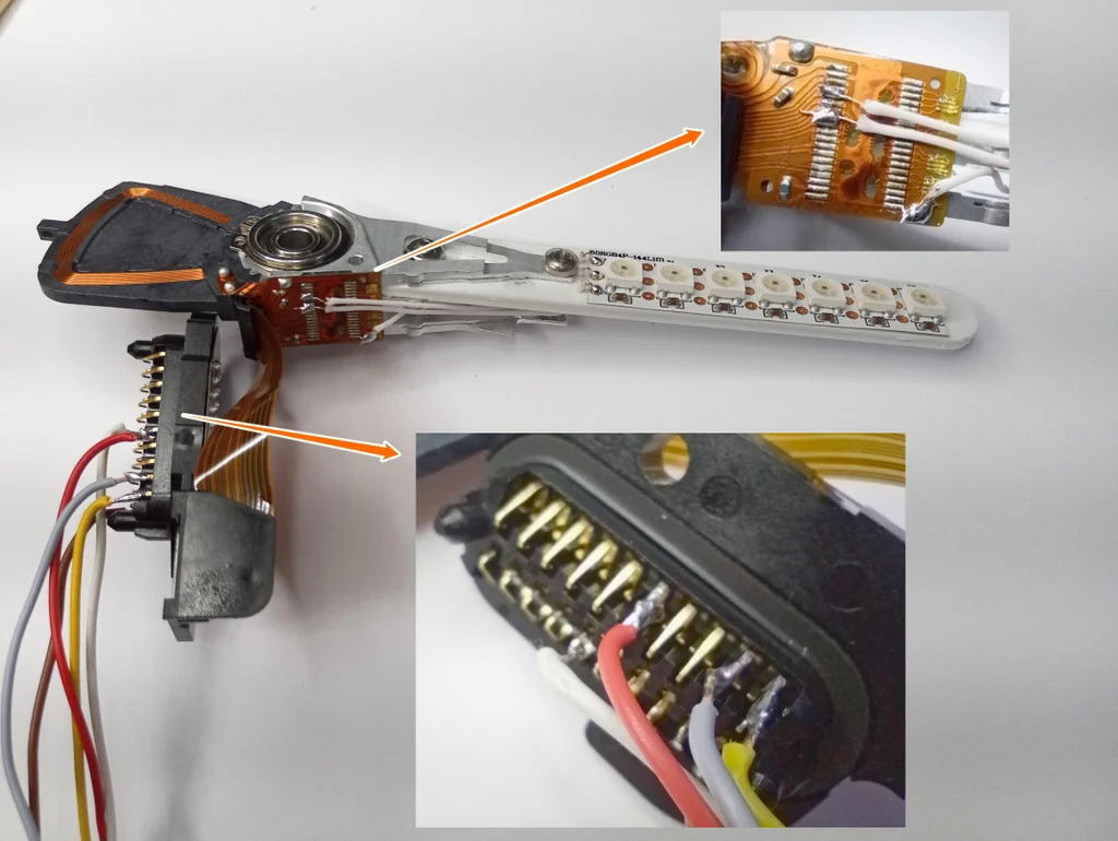
At least that’s what [Leo] did when he created “PendoLux”. The clock itself is pretty simple; like any POV project, it just requires a way to move an array of flashing LEDs back and forth rapidly enough that they can trick the eye into seeing a solid image. [Leo] put the read head mechanism of an old HDD into use for that, after stripping the platters and motor out of it first.
The voice coil and magnet of the head arm are left intact, while a 3D-printed arm carrying seven RGB LEDs replaces the old heads. [Leo] added a small spring to return the arm to a neutral position, and used an Arduino to drive the coil and flash the LEDs. Getting the timing just right was a matter of trial and error; he also needed to eschew the standard LED libraries because of his heavy use of interrupts and used direct addressing instead.
POV clocks may have dropped out of style lately — this hard drive POV clock and a CD-ROM version were posted years ago. But [Leo]’s clock is pretty good looking even for a work in progress, so maybe the style will be making a comeback.
Hackaday editors Elliot Williams and Mike Szczys flip through the index of great hacks. This week we learn of a co-existence attack on WiFi and Bluetooth radios called Spectra. The craftsmanship in a pneumatic drone is so awesome we don’t care that it doesn’t fly. Building a powerful TEA laser is partly a lesson in capacitor design. And join us in geeking out at the prospect of big rigs getting their juice from miles of overhead wires.
Take a look at the links below if you want to follow along, and as always, tell us what you think about this episode in the comments!
Video conferencing is nothing new, but the recent world events have made it much more mainstream than it has been in the past. Luckily, web camera technology is nothing new and most software can also show your screen. But what about your paper documents? Turns out that [John Nelson] can show you how to spend $5 for an old laptop camera module and put your documents center stage on your next Zoom, Skype or other video conferences.
This is especially good for things that would be hard to draw in real time during a conference like a quick sketch, a schematic, or as you can see in the post and the video demo below, chemical molecule diagrams.
It isn’t hard to imagine how this works, but getting a steady holder for the laptop does take a little workshop effort. There’s also an earlier version made to work with a desktop computer and has a few more dollars tied up in more substantial base.
We might have been tempted to make an Elmo clone by taking a nice desk lamp and just strapping the camera to it. However, that would cost a lot more than $5 unless you are good at shopping thrift stores.
We have seen a few projects using these laptop cameras lately. They are cheap, easy to stick into things and work with normal USB connections. Of course, conferencing also involves audio, so you might want to think about adding a mute switch.
Last weekend, DEF CON held their “SAFE MODE” conference: instead of meeting at a physical venue, the entire conference was held online. All the presentations are available on the official DEF CON YouTube channel. We’ll cover a few of the presentations here, and watch out for other articles on HaD with details on the other talks that we found interesting.
Lock Picking
We don’t often dabble with physical security in our weekly roundup, but the lockpicking track is a big part of DEF CON. It’s a perfect excuse. So first up is a presentation about safe-cracking by [Jared Dygert]. You know the scene in the movie where the super thief cracks the safe by listening to it as he spins the dial? Yeah, forget that. The real technique doesn’t have anything to do with sound. A typical three-number combination safe has a trio of wheels inside the locking mechanism. Each of these wheels have a narrow slot, or gate, cut into them. When the three gates are lined up, the locking bar can fall into the slots, and a fourth wheel pulls the lock open.
That fourth wheel is the key to cracking a safe, as the locking bar rides directly on the outer surface of that wheel. The gate there is shaped differently from the others, with a curved edge on one side. It’s possible to feel exactly when the locking bar begins to drop into that gate. Because of the shape of that special fourth gate, it’s possible to measure the width, and by extension discover how far the locking bar has dropped. As the three wheels with unknown gates aren’t perfectly the same size, it’s possible to map the surface of the largest wheel and discover where the gate is. For a demonstration, watch the video linked above.
It’s hard to mention lock pickers without giving a shout-out to a pair of YouTubers, [Bosnianbill] and [LockPickingLawyer]. I came across a video this week from the lawyer of this dynamic duo, and it’s the most polite-yet-savage burn I’ve seen in a long while. Before you watch, know that the tool he uses is the Sparrows Disk Pick, and he and [Bosnianbill] worked together to design and beta test the tool.
A Dragon’s Achilles Heel
Snapdragon processors are quite popular in high end Android devices. These processors are packaged in a System on a Chip (SoC), which really contains a number of processors and devices. A Snapdragon SoC has a processor, GPU, Wifi modem, Image Signal Processor, and Digital Signal Processor. We talk a lot about security vulnerabilities in the software that runs on the CPU. What if I told you there were vulnerabilities in software running on those other processor cores, too? Well yeah, there will obviously be poorly written code there too. What hasn’t been obvious is how to find those vulnerabilities, and then how to attack them. Now, thanks to the researchers at Checkpoint Security, and their work on Achilles, we know a way to attack the dragon’s heel.
When an app needs to use the Snapdragon DSP, it invokes a serialization library, referred to as a stub.so file. Once the data is serialized, it is transferred to the DSP over shared memory, using the DSRPC driver. Along with the data to be processed, the application also sends along the processing library. This library is essentially the program that will run on the DSP. There is a code signing requirement. The DSP will only run code that has been signed by Qualcomm, but there is no version checking or revocation mechanism. In essence, any DSP library Qualcomm has ever signed is allowed to run on every DSP. To make matters worse, an Android app can access the DSP with no special permissions. Even if only one vulnerable DSP library were created, the weak code-signing scheme means that every Qualcomm DSP is vulnerable.
A few articles are suggesting that a malicious video or audio file downloaded from the net can trigger the vulnerability. This is incorrect. So far, only an application with direct access to the DSP can launch the attack. During the virtual press conference on Thursday, this was addressed by a Checkpoint researcher. While it’s theoretically possible for a video file to trigger a yet-to-be-found vulnerability, the flaw they found is a deserialization bug that is only triggered by a malicious serialization process. This means data processed using the official serialization process can’t trigger this vulnerability. The deserialization bug is actually rooted in the Software Development Kit that is distributed to OEMs and used to build the individual libraries. To put it simply, it’s not just one or two DSP library that is vulnerable, but all of them, which is where the “400 vulnerabilities” comes from.
Once a malicious application uses the vulnerability to break the deserialization routine and achieve code execution, what’s next? Qualcomm did at least do proper user/kernel separation, and an additional vulnerability is needed to escalate privilege up to full compromise. Once there, the primary threat is data leakage. The malware on the DSP can examine all the data that other applications share for processing. This likely means full access to the device’s microphone, and potentially camera when it is use. I was able to ask Checkpoint if they had managed to permanently modify the DSP’s firmware, as this sort of modification could survive through even a full factory reset. Their response is that they had investigated this question, and had been unable to make a permanent modification. This isn’t surprising as firmware of this nature is often not stored on the SoC itself, but is loaded from the main system flash memory as a part of the boot process.
So far, this set of vulnerabilities doesn’t pose a huge risk to the everyday user. The normal advice of not installing untrusted applications is still the best solution. The major danger here is that DSP malware could be used by an installed application to access the microphone audio without having any permissions. The process of fixing this set of vulnerabilities will be a headache for years to come. Not only will the individual vulnerable libraries need to be updated, the signing problems will need to be addressed so vulnerable libraries can’t be trivially executed. It does not appear that any fixes are available at this time.
For your viewing pleasure, one of the other excellent talks from DEF CON is below, where [Christopher Wade] dives deeply into firmware hacking, primarily on Android devices.
Intel Leaks 20 GB
A very large dump of Intel code and documentation was made public last week. The official Intel explanation a partner or customer must have abused their access to Intel’s “Resource and Design Center”, and leaked the documents from there. According to ZDnet’s coverage, though, the leaker claims to have found the documentation on a CDN server that wasn’t properly configured.
Regardless, the leak seems to be genuine. Time will tell what interesting tidbits are contained in the 20 GB that were just released. As the information is all marked confidential, there is a bit of a legal grey area as to what programmers are allowed to do with the information.
Robot Exorcist?
And finally, just for fun, researchers at McAfee found a set of vulnerabilities in the “temi” teleconference robot. In a surprisingly detailed write-up, they describe how an attacker can possess the robot without any valid credentials, use it to drive the robot around and spy on whatever is nearby. McAfee researchers have shared all their findings with temi’s vendor, and fixes are already available.
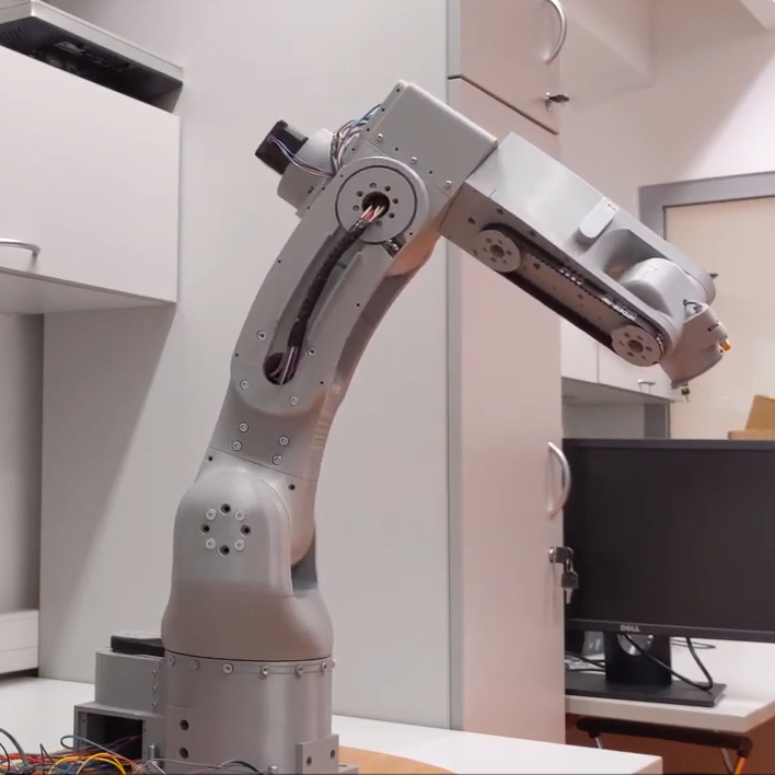
[Petar Crnjak]’s Faze4 is a open source robotic arm with 3D printable parts, inspired in part by the design of industrial robot arms. In particular, [Petar] aimed to hide wiring and cables inside the arm as much as possible, and the results look great! Just watch it move in the video below.
Cycloidal gearboxes have been showing up in robotic arm projects more and more, and Faze4 makes good use of them. Why cycloidal gears? They are readily 3D printed and offer low backlash, which makes them attractive for robotic applications. There’s no need to design cycloidal gears from scratch, either. [Petar] found this cycloidal gear generator in OnShape extremely useful when designing Faze4.
The project’s GitHub repository has all the design files, as well as some video demonstrations and a link to assembly documentation for anyone who would like to make their own. Watch Faze4 go through some test movements in the video embedded below.
Cycloidal gearboxes, which have similarities to both planetary gearing and strain-wave gears, can be mesmerizing to watch. Check out our previous coverage for more information on what they are and how they work.
[Petar Crnjak]’s Faze4 is a open source robotic arm with 3D printable parts, inspired in part by the design of industrial robot arms. In particular, [Petar] aimed to hide wiring and cables inside the arm as much as possible, and the results look great! Just watch it move in the video below.
Cycloidal gearboxes have been showing up in robotic arm projects more and more, and Faze4 makes good use of them. Why cycloidal gears? They are readily 3D printed and offer low backlash, which makes them attractive for robotic applications. There’s no need to design cycloidal gears from scratch, either. [Petar] found this cycloidal gear generator in OnShape extremely useful when designing Faze4.
The project’s GitHub repository has all the design files, as well as some video demonstrations and a link to assembly documentation for anyone who would like to make their own. Watch Faze4 go through some test movements in the video embedded below.
Cycloidal gearboxes, which have similarities to both planetary gearing and strain-wave gears, can be mesmerizing to watch. Check out our previous coverage for more information on what they are and how they work.
[Petar Crnjak]’s Faze4 is a open source robotic arm with 3D printable parts, inspired in part by the design of industrial robot arms. In particular, [Petar] aimed to hide wiring and cables inside the arm as much as possible, and the results look great! Just watch it move in the video below.
Cycloidal gearboxes have been showing up in robotic arm projects more and more, and Faze4 makes good use of them. Why cycloidal gears? They are readily 3D printed and offer low backlash, which makes them attractive for robotic applications. There’s no need to design cycloidal gears from scratch, either. [Petar] found this cycloidal gear generator in OnShape extremely useful when designing Faze4.
The project’s GitHub repository has all the design files, as well as some video demonstrations and a link to assembly documentation for anyone who would like to make their own. Watch Faze4 go through some test movements in the video embedded below.
Cycloidal gearboxes, which have similarities to both planetary gearing and strain-wave gears, can be mesmerizing to watch. Check out our previous coverage for more information on what they are and how they work.
We see a ton of clock projects around these parts, and being hackers, we love to feature them all. But every once in a while we stumble upon a great new way to display the time that really gets our attention and requires a closer look, such as this moving fridge magnet clock.
The fridge magnets [Craig Colvin] built this unique clock around are the colorful plastic kinds that have adorned the lower regions of refrigerators in toddler-filled households for ages. Instead of residing on a fridge, [Craig] laminated a sheet of white acrylic to a thin sheet of steel, to give the magnets something to hold onto. Moving the numbers is the job of a CoreXY-style mechanism. The belt-driven Cartesian movement maneuvers a head to to the right location to pick up a number; a servo in the head moves two powerful magnets into position under the number. The head then moves the number to the right spot, releases its magnets, and the number stays put on the board. You can see it in action in the video after the break.
While we love this as it is, it brings to mind some great mods. One can imagine the addition of letters to make a legit word clock, or to just add a calendar display. We’d also love to see these magnets in their natural habitat by building this into the door of a working fridge.
Direct memory access (DMA) systems in computers are more powerful than you might think, and [Bruce Land] and [Joseph Primmer] have done some clever hacking to take full advantage of this on the PIC32 microcontrollers. This is a cool proof-of-concept hack — you can do general computing in the DMA subsystem without using the CPU at all if you don’t mind taking your time — but they also include two useful examples: a direct digital synthesis machine and a random number generator. Both of these run using exactly 0% CPU time.
How do they do it? DMA is a mechanism for shuttling data around in memory or between hardware peripherals without involving the CPU. Say you want to take a large block of memory containing music, and spit it out slowly to an I2S audio converter. A DMA subsystem could be configured to take an interrupt from the sound chip, pass it a chunk of data, increment the data pointer, and wait for the next interrupt.
The gimmick, which goes back at least to [Rushanan] and [Checkoway]’s “Run DMA” paper, is that you can modify the memory source and destination addresses of one DMA service from another DMA service, and that some registers automatically perform mathematical operations on whatever data is put into them. Combine these together, and you’ve got transport-triggered programming.
(An awesome side-note: our own [Al Williams] developed a one-instruction transport-triggered CPU way back in the day: the One Instruction Wonder.)
What is this good for? Writing simple helper applications that run independent of the CPU on a PIC32 microcontroller. [Land] and [Primmer]’s direct-digital synthesis example is a great one. But there are a lot of cases where you simply want to take in some new data and pre-process it a little bit before it enters the main program flow. While creating weird machines in the DMA engine might be a slower way to get it done, it keeps the CPU free for doing other stuff. We’re sure you’ll come up with something.
Have you ever tried to weigh a cat? For that matter, have you ever tried to get a cat to do anything they don’t want to do? The wilful independence of our feline companions is a large part of what endears them to us, and must have done ever since the ancient Egyptians first had a hybrid wildcat that became domesticated
No wonder it’s so hard to care for multiple cats with different dietary needs. But the mere act of weighing the cats just might be the key to automating their diets while giving them the choice of when they want to eat. It’s a task that [Psy0rz] has cracked with the Meowton, a weighing machine/feeder combo designed to regulate the diets of his various moggies.
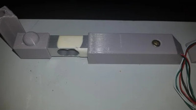
Cat scale uses a load sensor under each corner of the platform
The multi-faceted system involving a scale to weight the cat, a food hopper with dispenser, and a scale for the food bowl. The cat has to stand on the scale to eat, and the dispenser doles out some food when it detects this. It identifies each cat by weight, and controls the quantity dispensed accordingly to spread that cat’s allotted diet over the course of the day.
Behind it all is an ESP32, which delivers the stats to a web interface and makes them available for import to a database. He’s identified a flaw in the system, that two cats of the same weight could cause misidentification. To that end he has an RFID reader under way, but it’s still a work in progress. There is even a live stream of the unit in action.
We’re suckers for cats here, and while the various Hackaday Cats provide plenty of companionship and entertainment we’re always up for more. Over the years we’ve featured plenty of cat feeders, but only one cat elevator.
If you’re serious about engineering the things you build, you need to know the limits of the materials you’re working with. One of important way to characterize materials is to test the tensile strength — how much force it takes to pull a sample to the breaking point. Thankfully, with the right hardware, this is easy to measure and [CrazyBlackStone] has built a rig to do just that.
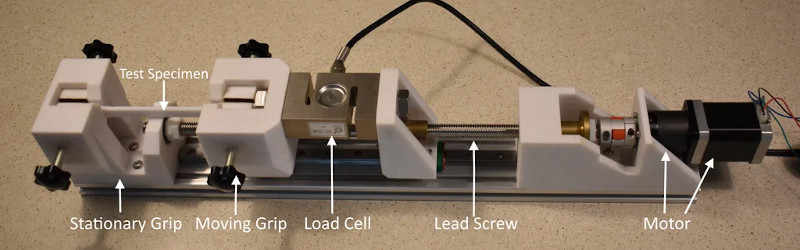
Built on a frame of aluminium extrusion, a set of 3D printed parts to hold everything in place. To apply the load, a stepper motor is used to slowly turn a leadscrew, pulling on the article under test. Tensile forces are measured with a load cell hooked up to an Arduino, which reports the data back to a PC over its USB serial connection.
It’s a straightforward way to build your first tensile tester, and would be perfect for testing 3D printed parts for strength. The STEP files (13.4 MB direct download) for this project are available, but [CrazyBlackStone] recommends waiting for version two which will be published this fall on Thingiverse although we didn’t find a link to that user profile.
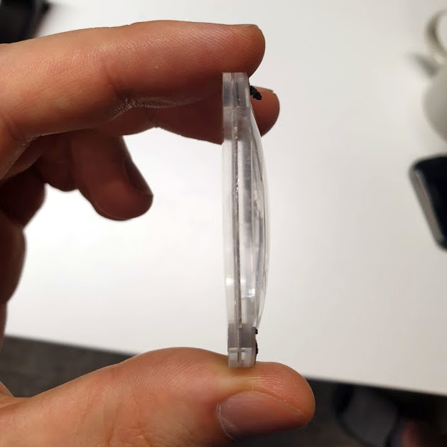
Valve’s unique multilayer lenses are far thinner than one might expect.
Want to see what exactly is inside the $500 (headset only price) Valve Index VR headset that was released last summer? Take a look at this teardown by [Ilja Zegars]. Not only does [Ilja] pull the device apart, but he identifies each IC and takes care to point out some of the more unique hardware aspects like the fancy diffuser on the displays, and the unique multilayered lenses (which are much thinner than one might expect.)
[Ilja] is no stranger to headset hardware design, and in addition to all the eye candy of high-res photographs, provides some insightful commentary to help make sense of them. The “tracking webs” pulled from the headset are an interesting bit, each is a long run of flexible PCB that connects four tracking sensors for each side of the head-mounted display back to the main PCB. These sensors are basically IR photodiodes, and detect the regular laser sweeps emitted by the base stations of Valve’s lighthouse tracking technology. [Ilja] also gives us a good look at the rod and spring mechanisms seen above that adjust distance between the two screens.
Typically, when we think of 3D printed parts, we think of unique parts with complex geometries that would be hard to fabricate with other techniques. Strength is rarely the first thing that comes to mind, due to the limitations of thermoplastics and the problem of delamination between layers. However, with smart design, it’s possible to print parts capable of great feats, just as [Brian]’s high-torque gearbox demonstrates.
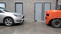
Pulling a car is a great way to show off the strength of your build.
The gearbox consists of entirely 3D-printed gears, along with the enclosure, with the only metal parts being a few bearings and shafts. Capable of being produced out of PLA on a regular FDM printer, [Brian] has successfully tested the gearbox up to 132 kg∗cm. The suspicion is that there may be more left in it, but some slippage was noticed in the gear train when trying to tow a Ford Focus with the handbrake still on.
Even better, with the addition of a potentiometer, the gearbox can be used as an incredibly tough servo. [Brian] demonstrates this by lifting 22 kg at a distance of 6 cm from the center of the output shaft. The servo does it with ease, though eventually falls off the bench due to not being held down properly.
It’s a build that shows it’s possible to use 3D-printed parts to do some decently heavy work in the real world, as long as you design appropriately. [Brian] does a great job of explaining what’s involved, discussing gear profile selection and other design choices that affect the final performance. We’ve seen similar work from others before, too. Video after the break.
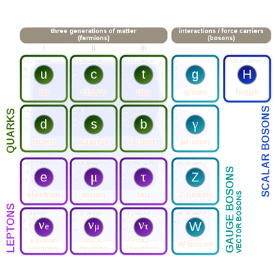
The holy grail of every particle physics experiment is the discovery of a new particle. Finding a new constituent of matter may earn you eternal glory within the history of physics. Unfortunately, since the last missing piece of the Standard Model, the Higgs boson, was discovered in 2012, and with still no clue about the nature of dark matter and dark energy, there is not much hope to stumble upon a new fundamental building block of matter any time soon.
Luckily, this is not true for composite particles, especially the strange world of quark matter still yields some potential for new discoveries. The latest of such was the observation of a new tetraquark by the LHCb experiment. But what the hell is a quark anyway and why is it named after a German dairy product?
The Proton Is Not Just a Dot
Up until the 1950s, it was believed that subatomic particles such as the neutron and proton are elementary, point-like particles with no inner structure. In the following decade, the progress made by accelerator experiments led to the discovery of an entire zoo of new particles. This sudden “particle explosion” irritated physicists who believed in the beauty of simplicity. Wolfgang Pauli exclaimed that had he foreseen this, he would have become a botanist instead. US physicist Willis Lamb suggested that the discovery of a new particle now ought to be punished with $10,000 fine instead of a Nobel Prize.
In 1964, Murray Gell-Mann and George Zweig independently came up with a model proposing that these new particles are not elementary but instead composed of a combination of new fundamental particles called quarks. The name was coined by Gell-Mann who pronounced it “kwork” and later adopted the spelling from the following cryptic line in James Joyce’s book Finnegans Wake.
Three quarks for Muster Mark!
Sure he has not got much of a bark
And sure any he has it’s all beside the mark.
While Gell-Mann interpreted the line as a call for drinks (“Three quarts for Mister…”) it is unclear what James Joyce really meant. Some think it represents the cry of a seagull while others attribute it to the German word for a kind of cottage cheese.
Definitive proof for the existence of quarks came in 1968 when experiments at the Stanford Linear Accelerator Center showed that the proton is not a point-like particle but instead contains some inner structure. Still, people only recognized later that what they observed were in fact quarks.
There are six different kinds of quarks (up, down, top, bottom, strange, charm) that have different masses and charges. For every quark there is also an antiparticle with the same mass but opposite charge. The proton, for example, consists of two up quarks (u) with charge +2/3 and one down quark (d) with charge -1/3, while a neutron consists of two down quarks and one up quark.
Like the electric force that acts on charged particles, each quark contains a color charge blue, green, or red, which makes it susceptible to the strong force. In nature, one can only observe color-neutral particles that consist either of three quarks with different colors (called baryons), or a quark-antiquark pair (called mesons).
The fact that one cannot produce isolated quarks is known as confinement. It can be understood as a peculiarity of the strong force that behaves similar to a rubber band. When trying to separate two quarks it becomes more and more difficult with increasing distance so that at some point it is energetically more favorable to create another quark-antiquark pair.
Tetraquarks and Pentaquarks
Invariant mass spectrum of J/ψ pairs measured by LHCb. The narrow peak slightly below 7000 MeV corresponds to the newly discovered tetraquark. Credit: LHCb collaboration
Baryons and mesons are not the only possibilities to combine quarks in a color-neutral way. A tetraquark is also viable, being a combination of four quarks qqqq, where q and q respectively refer to a quark and antiquark. A pentaquark qqqqq may even exist.
To search for penta- and tetraquarks one smashes together electrons or protons in an accelerator and analyses the particles produced in the collisions. Since such exotic particles have extremely short lifetimes, they cannot be directly observed in a detector. Instead one plots the number of recorded events vs. the so-called invariant mass, calculated from the energy and momentum of the final decay products. In this plot, a short-lived intermediate particle shows up as a narrow resonance peak. The position of the peak equals the mass of the particle while the width is inversely proportional to its lifetime.
The first indication for the existence of a tetraquark came in 2003 from the BELLE experiment in Japan. In the same year, another Japanese experiment called SLEP maybe saw a pentaquark. In the meantime, several penta- and tetraquarks have been unambiguously discovered. At the forefront of these discoveries was the LHCb experiment which confirmed the existence of a tetraquark in 2014 and one year later also discovered a pentaquark. The tetraquark discovered recently by LHCb is special because it consists of two charm quarks and two charm antiquarks cccc. All other tetraquarks observed so far have at most two heavy quarks and none of them is made of more than two quarks of the same type.
Why Do We Even Care?
You may wonder why people go through the effort of hunting for these exotic particles. As with most particle physics experiments, it is all about a better understanding of the fundamental forces of nature, in this case, the strong force described by quantum chromodynamics (QCD). Calculating the properties of bound quarks is fairly complicated and so the measurement of these exotic particles helps to test different theoretical models. For example, it is unclear if all quarks in a tetra- and pentaquark are tightly bound together or if they form a molecule-like, loosely bound combination of baryons and mesons. Discovering more of these particles and measuring their properties could help to resolve this question.
At any given time I’m likely to have multiple projects in-flight, by which of course I mean in various stages of neglect. My current big project is one where I finally feel like I have a chance to use some materials with real hacker street cred, like T-slot extruded aluminum profiles. We’ve all seen the stuff, the “Industrial Erector Set” as 80/20 likes to call their version of it. And we’ve all seen the cool projects made with it, from CNC machines to trade show displays, and in these pandemic times, even occasionally as sneeze guards in retail shops.
Aluminum T-slot profiles are wonderful to work with — strong, lightweight, easily connected with a wide range of fasteners, and infinitely configurable and reconfigurable as needs change. It’s not cheap by any means, but when you factor in the fabrication time saved, it may well be a net benefit to spec the stuff for a project. Still, with the projected hit to my wallet, I’ve been looking for more affordable alternatives.
My exploration led me into the bewilderingly rich world of aluminum extrusions. Even excluding mundane items like beer and soda cans, you’re probably surrounded by extruded aluminum products right now. Everything from computer heatsinks to window frames to the parts that make up screen doors are made from extruded aluminum. So how exactly is this ubiquitous stuff made?
The Die
The basic process for extruding aluminum is, outwardly, as simple to understand as the extrusion process used by a 3D-printer: heat material and force it through a die with the desired shape and size. But when PLA is replaced by giant aluminum log, and a Bowden cable and stepper motor by an enormous hydraulic ram, the details quickly cloud the simplicity of the underlying concept.
Die design is perhaps the most critical part of the extrusion process. Dies have to withstand tremendous forces at high temperatures, and must maintain their dimensional stability while doing so. Extrusion dies start life as round bars of tool steel up to a meter or more in diameter but typically around 30 cm. Dies are usually fairly thin in profile relative to their diameter, since the longer the path the aluminum takes as it passes through the die, the greater the friction it experiences. More friction means more force, which means bigger presses, more wear on the dies, and generally higher costs.
Dies are generally created by specialty manufacturers that employ skilled die design engineers and machinists. The process of turning a design into a die usually starts with roughing out the blank on a CNC lathe, then proceeds to a sequence of CNC milling operations. Electric discharge machining (EDM) is used extensively to get the fine detail needed to provide a smooth finish, and to achieve the precise geometry needed to control the flow of the aluminum through the die.
Most extrusions will have one or more hollow chambers, like the lumen of a pipe or, in the case of our 80/20 profiles, the negative space of the T-slots and the central bore. The die has to create those features, which require parts of the die to “float” in the incoming flow of softened metal. Diemakers accomplish this by suspending these features on arms that bridge the space in the upstream part of the die. The shape and surface finish of these arms has to be carefully designed so that the metal flows around them and joins together to create a smooth, continuous stream of material without voids, which could lead to weakness in the finished product.
Careful consideration of the hydrodynamic forces exerted by and upon the flowing metal are also important to die design. While the exit side of the die is pretty much exactly the size and shape of the finished extrusion, the entrance side is anything but. By some estimates, half of the energy used while extruding aluminum goes into overcoming friction between the metal and the die, so everything that can be done to reduce those forces is like money in the bank. The entrance of the die has to be designed to direct the incoming metal as smoothly and easily as possible into the final shape, which is part of the reason die designers include very generous draft angles over the width of the die.
The Squeeze
There are a number of different ways to approach the extrusion process, each with its own pros and cons. Direct extrusion is basically what you’re familiar with in 3D printing, or if you’ve ever used one of those squeezy things in a Play-Doh set: a slug of softened material is pressed against a die, which then flows through the die to assume its final shape. Indirect extrusion turns that around, forcing the die to move relative to the material. Both approaches have their pros and cons, and both result in extrusions with different metallurgical properties.
In either process, a large log of aluminum, called a billet, is heated in either a gas furnace or by induction. The temperature varies with the specific alloy and the complexity of the die, but it’s important to note that the billet is not melted, just softened. The die and much of the hydraulic press are also heated, to prevent thermal stresses from breaking anything in the machinery and to prevent the aluminum from cooling too soon and sticking to the die.
Aluminum extrusion presses generally have a horizontal orientation, with a massive hydraulic ram facing the die across a narrow gap. The preheated billet is placed into the gap, and the hydraulic ram starts to press it into the die (or, in indirect extrusion, moves the die over the material). The softened metal begins to flow into the spaces of the die, around the arms, and narrowing down into the final shape as it exits the die.
The growing extrusion exits the press and is almost immediately quenched with either air or, more commonly, a water bath. The quenching process is important, because as the extrusion exits the die it is still soft and liable to be deformed. Quenching also sets the crystal structure of the metals in the alloy, giving the finished extrusion its desired metallurgical properties.
Stretching and Aging
But even with quenching, the extrusions that come out of the die onto the long outfeed tables are far from complete. The tremendous forces exerted during extrusion coupled with the thermal stresses of quenching inevitably warps and twists the profiles. This is corrected with a stretching operation, where extrusions are literally picked up and stretched out the long way with hydraulic tools. This restores the profile to its intended shape; the few percent change in the length of the profile necessarily changes the profile dimensions slightly, a fact which has to be accounted for by the die designers.
Curiously, fresh extrusions need to be aged somewhat at elevated temperatures before reaching their final specified strength. This is accomplished in large aging towers over a period of hours to days, depending on the alloy. Aged extrusions are then cut to length, possibly have a finish applied — clear or dyed anodized finishes are very popular for 80/20 extrusions as they protect the aluminum from oxidation — and packaged for shipping.
Given the amount of material that goes into an aluminum extrusion, and the investment needed to run the massive machines that do the job, it’s easy to understand why 80/20 profiles cost what they do. So now maybe I’ll just bite the bullet and order what I need.
At any given time I’m likely to have multiple projects in-flight, by which of course I mean in various stages of neglect. My current big project is one where I finally feel like I have a chance to use some materials with real hacker street cred, like T-slot extruded aluminum profiles. We’ve all seen the stuff, the “Industrial Erector Set” as 80/20 likes to call their version of it. And we’ve all seen the cool projects made with it, from CNC machines to trade show displays, and in these pandemic times, even occasionally as sneeze guards in retail shops.
Aluminum T-slot profiles are wonderful to work with — strong, lightweight, easily connected with a wide range of fasteners, and infinitely configurable and reconfigurable as needs change. It’s not cheap by any means, but when you factor in the fabrication time saved, it may well be a net benefit to spec the stuff for a project. Still, with the projected hit to my wallet, I’ve been looking for more affordable alternatives.
My exploration led me into the bewilderingly rich world of aluminum extrusions. Even excluding mundane items like beer and soda cans, you’re probably surrounded by extruded aluminum products right now. Everything from computer heatsinks to window frames to the parts that make up screen doors are made from extruded aluminum. So how exactly is this ubiquitous stuff made?
The Die
The basic process for extruding aluminum is, outwardly, as simple to understand as the extrusion process used by a 3D-printer: heat material and force it through a die with the desired shape and size. But when PLA is replaced by giant aluminum log, and a Bowden cable and stepper motor by an enormous hydraulic ram, the details quickly cloud the simplicity of the underlying concept.
Die design is perhaps the most critical part of the extrusion process. Dies have to withstand tremendous forces at high temperatures, and must maintain their dimensional stability while doing so. Extrusion dies start life as round bars of tool steel up to a meter or more in diameter but typically around 30 cm. Dies are usually fairly thin in profile relative to their diameter, since the longer the path the aluminum takes as it passes through the die, the greater the friction it experiences. More friction means more force, which means bigger presses, more wear on the dies, and generally higher costs.
Dies are generally created by specialty manufacturers that employ skilled die design engineers and machinists. The process of turning a design into a die usually starts with roughing out the blank on a CNC lathe, then proceeds to a sequence of CNC milling operations. Electric discharge machining (EDM) is used extensively to get the fine detail needed to provide a smooth finish, and to achieve the precise geometry needed to control the flow of the aluminum through the die.
Most extrusions will have one or more hollow chambers, like the lumen of a pipe or, in the case of our 80/20 profiles, the negative space of the T-slots and the central bore. The die has to create those features, which require parts of the die to “float” in the incoming flow of softened metal. Diemakers accomplish this by suspending these features on arms that bridge the space in the upstream part of the die. The shape and surface finish of these arms has to be carefully designed so that the metal flows around them and joins together to create a smooth, continuous stream of material without voids, which could lead to weakness in the finished product.
Careful consideration of the hydrodynamic forces exerted by and upon the flowing metal are also important to die design. While the exit side of the die is pretty much exactly the size and shape of the finished extrusion, the entrance side is anything but. By some estimates, half of the energy used while extruding aluminum goes into overcoming friction between the metal and the die, so everything that can be done to reduce those forces is like money in the bank. The entrance of the die has to be designed to direct the incoming metal as smoothly and easily as possible into the final shape, which is part of the reason die designers include very generous draft angles over the width of the die.
The Squeeze
There are a number of different ways to approach the extrusion process, each with its own pros and cons. Direct extrusion is basically what you’re familiar with in 3D printing, or if you’ve ever used one of those squeezy things in a Play-Doh set: a slug of softened material is pressed against a die, which then flows through the die to assume its final shape. Indirect extrusion turns that around, forcing the die to move relative to the material. Both approaches have their pros and cons, and both result in extrusions with different metallurgical properties.
In either process, a large log of aluminum, called a billet, is heated in either a gas furnace or by induction. The temperature varies with the specific alloy and the complexity of the die, but it’s important to note that the billet is not melted, just softened. The die and much of the hydraulic press are also heated, to prevent thermal stresses from breaking anything in the machinery and to prevent the aluminum from cooling too soon and sticking to the die.
Aluminum extrusion presses generally have a horizontal orientation, with a massive hydraulic ram facing the die across a narrow gap. The preheated billet is placed into the gap, and the hydraulic ram starts to press it into the die (or, in indirect extrusion, moves the die over the material). The softened metal begins to flow into the spaces of the die, around the arms, and narrowing down into the final shape as it exits the die.
The growing extrusion exits the press and is almost immediately quenched with either air or, more commonly, a water bath. The quenching process is important, because as the extrusion exits the die it is still soft and liable to be deformed. Quenching also sets the crystal structure of the metals in the alloy, giving the finished extrusion its desired metallurgical properties.
Stretching and Aging
But even with quenching, the extrusions that come out of the die onto the long outfeed tables are far from complete. The tremendous forces exerted during extrusion coupled with the thermal stresses of quenching inevitably warps and twists the profiles. This is corrected with a stretching operation, where extrusions are literally picked up and stretched out the long way with hydraulic tools. This restores the profile to its intended shape; the few percent change in the length of the profile necessarily changes the profile dimensions slightly, a fact which has to be accounted for by the die designers.
Curiously, fresh extrusions need to be aged somewhat at elevated temperatures before reaching their final specified strength. This is accomplished in large aging towers over a period of hours to days, depending on the alloy. Aged extrusions are then cut to length, possibly have a finish applied — clear or dyed anodized finishes are very popular for 80/20 extrusions as they protect the aluminum from oxidation — and packaged for shipping.
Given the amount of material that goes into an aluminum extrusion, and the investment needed to run the massive machines that do the job, it’s easy to understand why 80/20 profiles cost what they do. So now maybe I’ll just bite the bullet and order what I need.
At any given time I’m likely to have multiple projects in-flight, by which of course I mean in various stages of neglect. My current big project is one where I finally feel like I have a chance to use some materials with real hacker street cred, like T-slot extruded aluminum profiles. We’ve all seen the stuff, the “Industrial Erector Set” as 80/20 likes to call their version of it. And we’ve all seen the cool projects made with it, from CNC machines to trade show displays, and in these pandemic times, even occasionally as sneeze guards in retail shops.
Aluminum T-slot profiles are wonderful to work with — strong, lightweight, easily connected with a wide range of fasteners, and infinitely configurable and reconfigurable as needs change. It’s not cheap by any means, but when you factor in the fabrication time saved, it may well be a net benefit to spec the stuff for a project. Still, with the projected hit to my wallet, I’ve been looking for more affordable alternatives.
My exploration led me into the bewilderingly rich world of aluminum extrusions. Even excluding mundane items like beer and soda cans, you’re probably surrounded by extruded aluminum products right now. Everything from computer heatsinks to window frames to the parts that make up screen doors are made from extruded aluminum. So how exactly is this ubiquitous stuff made?
The Die
The basic process for extruding aluminum is, outwardly, as simple to understand as the extrusion process used by a 3D-printer: heat material and force it through a die with the desired shape and size. But when PLA is replaced by giant aluminum log, and a Bowden cable and stepper motor by an enormous hydraulic ram, the details quickly cloud the simplicity of the underlying concept.
Die design is perhaps the most critical part of the extrusion process. Dies have to withstand tremendous forces at high temperatures, and must maintain their dimensional stability while doing so. Extrusion dies start life as round bars of tool steel up to a meter or more in diameter but typically around 30 cm. Dies are usually fairly thin in profile relative to their diameter, since the longer the path the aluminum takes as it passes through the die, the greater the friction it experiences. More friction means more force, which means bigger presses, more wear on the dies, and generally higher costs.
Dies are generally created by specialty manufacturers that employ skilled die design engineers and machinists. The process of turning a design into a die usually starts with roughing out the blank on a CNC lathe, then proceeds to a sequence of CNC milling operations. Electric discharge machining (EDM) is used extensively to get the fine detail needed to provide a smooth finish, and to achieve the precise geometry needed to control the flow of the aluminum through the die.
Most extrusions will have one or more hollow chambers, like the lumen of a pipe or, in the case of our 80/20 profiles, the negative space of the T-slots and the central bore. The die has to create those features, which require parts of the die to “float” in the incoming flow of softened metal. Diemakers accomplish this by suspending these features on arms that bridge the space in the upstream part of the die. The shape and surface finish of these arms has to be carefully designed so that the metal flows around them and joins together to create a smooth, continuous stream of material without voids, which could lead to weakness in the finished product.
Careful consideration of the hydrodynamic forces exerted by and upon the flowing metal are also important to die design. While the exit side of the die is pretty much exactly the size and shape of the finished extrusion, the entrance side is anything but. By some estimates, half of the energy used while extruding aluminum goes into overcoming friction between the metal and the die, so everything that can be done to reduce those forces is like money in the bank. The entrance of the die has to be designed to direct the incoming metal as smoothly and easily as possible into the final shape, which is part of the reason die designers include very generous draft angles over the width of the die.
The Squeeze
There are a number of different ways to approach the extrusion process, each with its own pros and cons. Direct extrusion is basically what you’re familiar with in 3D printing, or if you’ve ever used one of those squeezy things in a Play-Doh set: a slug of softened material is pressed against a die, which then flows through the die to assume its final shape. Indirect extrusion turns that around, forcing the die to move relative to the material. Both approaches have their pros and cons, and both result in extrusions with different metallurgical properties.
In either process, a large log of aluminum, called a billet, is heated in either a gas furnace or by induction. The temperature varies with the specific alloy and the complexity of the die, but it’s important to note that the billet is not melted, just softened. The die and much of the hydraulic press are also heated, to prevent thermal stresses from breaking anything in the machinery and to prevent the aluminum from cooling too soon and sticking to the die.
Aluminum extrusion presses generally have a horizontal orientation, with a massive hydraulic ram facing the die across a narrow gap. The preheated billet is placed into the gap, and the hydraulic ram starts to press it into the die (or, in indirect extrusion, moves the die over the material). The softened metal begins to flow into the spaces of the die, around the arms, and narrowing down into the final shape as it exits the die.
The growing extrusion exits the press and is almost immediately quenched with either air or, more commonly, a water bath. The quenching process is important, because as the extrusion exits the die it is still soft and liable to be deformed. Quenching also sets the crystal structure of the metals in the alloy, giving the finished extrusion its desired metallurgical properties.
Stretching and Aging
But even with quenching, the extrusions that come out of the die onto the long outfeed tables are far from complete. The tremendous forces exerted during extrusion coupled with the thermal stresses of quenching inevitably warps and twists the profiles. This is corrected with a stretching operation, where extrusions are literally picked up and stretched out the long way with hydraulic tools. This restores the profile to its intended shape; the few percent change in the length of the profile necessarily changes the profile dimensions slightly, a fact which has to be accounted for by the die designers.
Curiously, fresh extrusions need to be aged somewhat at elevated temperatures before reaching their final specified strength. This is accomplished in large aging towers over a period of hours to days, depending on the alloy. Aged extrusions are then cut to length, possibly have a finish applied — clear or dyed anodized finishes are very popular for 80/20 extrusions as they protect the aluminum from oxidation — and packaged for shipping.
Given the amount of material that goes into an aluminum extrusion, and the investment needed to run the massive machines that do the job, it’s easy to understand why 80/20 profiles cost what they do. So now maybe I’ll just bite the bullet and order what I need.
It may be named after the most famous volleyball in history, but “Wilson” isn’t just a great conversationalist. [Hayden Brophy] built the free-drifting satellite buoy to see if useful science can be done with off-the-shelf hardware and on a shoestring budget. And from the look of the data so far, Wilson is doing pretty well.
Wilson belongs to a class of autonomous vessels known as drifters, designed to float along passively in the currents of the world’s ocean. The hull of [Hayden]’s drifter is a small Pelican watertight case, which contains all the electronics: Arduino Pro Trinket, GPS receiver, a satellite modem, and a charger for the LiPo battery. The lid of the case is dominated by a 9 W solar panel, plus the needed antennas for GPS and the Iridium uplink and a couple of sensors, like a hygrometer and a thermometer. To keep Wilson bobbing along with his solar panel up, there’s a keel mounted to the bottom of the case, weighted with chains and rocks, and containing a temperature sensor for the water.
Wilson is programmed to wake up every 12 hours and uplink position and environmental data as he drifts along. The drifter was launched into the heart of the Gulf Stream on August 8, about 15 nautical miles off Marathon Key in Florida, by [Captain Jim] and the very happy crew of the “Raw Deal”. As of this writing, the tracking data shows that Wilson is just off the coast of Miami, 113 nautical miles from launch, and drifting along at a stately pace of 2.5 knots. Where the buoy ends up is anyone’s guess, but we’ve seen similar buoys make it all the way across the Atlantic, so here’s hoping that hurricane season is kind to Wilson.
We think this is great, and congratulations to [Hayden] for organizing a useful and interesting project.
Super Soakers were great fun back in the day, but adults tend to get tired of the manual labour of pumping pretty quickly. [Sean] decided to build something a touch more modern, coming up with this head-tracking water blaster.
The water spray tracks the movement of the wearer’s head. With a camera mounted on the nozzle, this allows the user to simply look to designate targets. Similar technology is used in military fighter jets.
To eliminate pumping, the build instead enlists the services of an electric pump, powered by a 12 V battery. Pushing water through a tube into a 3D printed nozzle, it provides a fat stream of water with around 5 meters range, with little effort from the user. The nozzle is fitted into a NES Zapper, and attached to a servo pan-tilt platform. The camera is mounted on the water gun, and hooked up to a set of Fat Shark FPV goggles with an IMU unit. When the user looks around, the water gun moves in sync with their head movements. This allows for the user to look at targets to hit them with the water stream, a very intuitive method of aiming.
It’s a fun build that’s perfect for the summer, and an easy one to recreate for anyone with some spare servos and FPV gear. Of course, with a little face-tracking software, it would be easy to hit targets automatically. Video after the break.
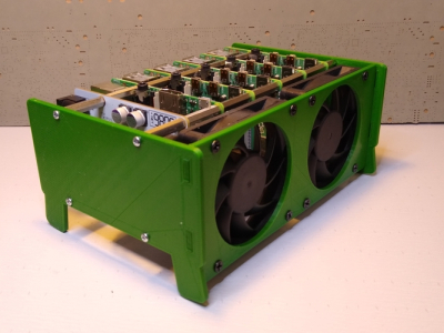
It isn’t that hard to assemble an array of Raspberry Pi boards and there are several reasons you might want to do so. The real trick is getting power to all of them and cooling all of them without having a mess of wires and keeping them all separated. The ClusterCTRL stack lets you stack up to five Raspberry Pi boards together. The PCB aligns vertically along the side of the stack of Pis with sockets for each pin header. Using a single 12 to 24V supply, it provides power for each board, a USB power connection, and provisions for two fans. There is also a USB port to control the fans and power.
There’s also a software component to deliver more granular control. Without using the software, the PI’s power on in one second and monitor a GPIO pin to control the fans. With the software, you can turn on or off individual nodes, gang the two fans to turn on together, and even add more stacks.
There is a case that you can print from STL files, although you can buy them preprinted on the Tindie listing where the bulk of information on ClusterCTRL is found. You could also have a 3D printing vendor run off a copy for you if you’d rather.
The power supply is a 10A 5.1V DC to DC converter. That works out to 2A per Pi and 51W total. The power supply for the input, then, needs to be enough to cover 51W, the power for the fans, and some overhead for regulator inefficiency and other small overhead.
We’ve seen a lot of Pi clusters over the years including one that is a good learning tool for cluster management. Of course, there’s always the Oracle cluster with 1,060 boards, which is going to take a bigger power supply.








 There is