If we count all the screens in our lives, it takes a hot minute. Some of them are touchscreens, some need a mouse or keyboard, but we are accustomed to all the input devices. Not everyone can use the various methods, like cerebral palsy patients who rely on eye-tracking hardware. Traditionally, that only works on the connected computer, so switching from a chair-mounted screen to a tablet on the desk is not an option. To give folks the ability to control different computers effortlessly [Zack Freedman] is developing a head-mounted eye-tracker that is not tied to one computer. In a way, this is like a KVM switch, but way more futuristic. [Tony Stark] would be proud.
An infrared detector on the headset identifies compatible screens in line of sight and synchs up with its associated HID dongle. A headset-mounted color camera tracks the head position in relation to the screen while an IR camera scans the eye to calculate where the user is focusing. All the technology here is proven, but this new recipe could be a game-changer to anyone who has trouble with the traditional keyboard, mouse, and touchscreen. Maybe QR codes could assist the screen identification and orientation like how a Wii remote and sensor bar work together.
Hackaday editors Mike Szczys and Elliot Williams dish up a hot slice of the week’s hardware hacks. We feature a lot of clocks on Hackaday, but few can compare to the mechanical engineering elegance of the band-saw-blade-based ratcheting clock we swoon over on this week’s show. We’ve found a superb use of a six-pin microcontroller, peek in on tire (or is that tyre) wear particles, and hear the sounds of 500 mph RC gliders. It turns out that 3D printers are the primordial ooze for both pumping water and positioning cameras. This episode comes to a close by getting stressed out over concrete.
Take a look at the links below if you want to follow along, and as always, tell us what you think about this episode in the comments!
Inspired by the famous lava lamp, [Mojoptix] wanted to build a creation of his own with a similarly organic, changing lighting effect. However, rather than flowing heated wax, he created a lamp with pseudo-random effects his own way.
The lamp itself is built around a shadow-puppet concept, using a pair of rotating apetures that [Mojoptix] 3D printed. The apetures turn, one in front of the other, and are lit from behind by an IKEA LED light. As the apetures rotate, they present a slowly varying path for the light from the LED, which is projected onto a paper screen placed in in front of the assembly. To generate the long-period rotation, the rotating assembly is turned by the minute hand of a common clock movement. It’s a great way to get a slow-rotating motor and gearbox setup on the cheap, as long as your torque requirements are absolutely miniscule.
Ah, the ever-present PDF, and our love-hate relationship with the format. We’ve lost count of how many vulnerabilities have been fixed in PDF software, but it’s been a bunch over the years. This week, we’re reminded that Adobe isn’t the only player in PDF-land, as Foxit released a round of updates, and there were a couple serious problems fixed. Among the vulnerabilities, a handful could lead to RCE, so if you use or support Foxit users, be sure to go get them updated.
PunkBuster
Remember PunkBuster? It’s one of the original anti-cheat solutions, from way back in 2000. The now-classic Return to Castle Wolfenstein was the first game to support PunkBuster to prevent cheating. It’s not the latest or greatest, but PunkBuster is still running on a bunch of game servers even today. [Daniel Prizmant] and [Mauricio Sandt] decided to do a deep dive project on PunkBuster, and happened to find an arbitrary file-write vulnerability, that could easily compromise a PB enabled server.
One of the functions of PunkBuster is a remote screenshot capture. If a server admin thinks a player is behaving strangely, a screenshot request is sent. I assume this targets so-called wallhack cheats — making textures transparent, so the player can see through walls. The problem is that the server logic that handles the incoming image has a loophole. If the filename ends in .png as expected, some traversal attack checks are done, and the png file is saved to the server. However, if the incoming file isn’t a png, no transversal detection is done, and the file is naively written to disk. This weakness, combined with the stateless nature of screenshot requests, means that any connected client can write any file to any location on the server at any time. To their credit, even Balance, the creators of PunkBuster, quickly acknowledged the issue, and have released an update to fix it.
The good folks at VDA Labs have a thing for fuzzing, and recently, they turned their attention toward MP3Gain, an open source MP3 normalizer. Using the Mayhem engine, they found a handful of crashes, and discovered one that could lead to code execution. The crash is the result of a malformed mp3 file, and not enough validation while loading the file.
While MP3Gain probably isn’t the most likely attack vector, it isn’t hard to imagine a scenario where it could be used. As far as I see, an updated release hasn’t been made to address this issue yet. Enough information is out there, that an attacker could potentially build a working exploit, so if you use MP3Gain, be extra cautious until the update is available.
Threading The NAT Needle
Network Address Translation (NAT) is a blessing and a curse. It has given us several years of breathing room for IPv4, and managed to give everyone a sane firewall setup by default. On the other hand, peer to peer connections and UDP packets can be particularly hard to push through a NAT router. This is an issue for torrents, SIP phone calls, and VPN solutions like OpenVPN and Wireguard. There have been various solutions over the years, like a STUN server for SIP, and UPnP to automate temporary port forwards.
Tailscale is a commercial company providing a mesh VPN service using Wireguard, and they recently published an in-depth guide about their techniques to navigate NAT firewalls. It’s pretty much all you ever wanted to know about the subject, so give it a read, or just make a mental note that it’s there for the next time you find yourself facing a tricky NAT firewall problem.
Bullet time became the hottest new cinema effect after it burst on the scene in The Matrix (1999). Back then, the cutting edge special effects required serious hardware and serious processing power to do the job. These days, of course, things have moved along somewhat. [Eric Paré] is no stranger to a high-end setup, but wanted to see what could be done at the lower end of the market. (Video, embedded below.)
Rather then relying on a bank of expensive DSLRs, [Eric] decided to try building a bullet-time camera rig out of 15 Raspberry Pis, and the standard Raspberry Pi Camera. Whereas just one camera in one of his professional setups may cost well over $1000, this entire rig was likely built for less than that in its entirety.
Initial results were jerky and unappealing, but [Eric] persevered. One of the biggest problems was inaccuracy in the camera assemblies, as they were stuck on with thermal paste. With some custom mods and tweaks, [Eric] was eventually able to get things to a passable state. It also has the benefit, compared to a DSLR rig, that the cameras can be mounted much more closely together due to their small size.
The Nintendo 64 was lauded for bringing quality 3D graphics and analog stick controls to the console realm, way back in 1996. Unfortunately, those analog sticks were never very good; if you’ve ever played four player Mario Kart 64, you know how it feels to be stuck with that controller. For a superior experience, consider building an adapter and upgrading to the GameCube controller instead.
Cube64 is a project that allows GameCube controllers to work with the original Nintendo 64 hardware. Using a PIC18F14K22 in its DIY version, or a PIC18F24Q10 in the SMD version, it’s the product of much work by [scanlime] and [darthcloud] to reverse engineer the N64 and GC controller protocols. The GameCube’s many buttons and sticks allow for easy mapping to the N64’s original button layout, and the hardware provides plenty of calibration options and maps to get things working exactly the way you like for the game you’re playing.
The holy grail of computer languages is to write code once and have it deploy effortlessly everywhere. Java likes to take credit for the idea, but UCSD P-Code was way before that and you could argue that mainframes had I/O abstraction like Fortran unit numbers even earlier. More modern efforts include Qt, GTK, and other things. Naturally, all of these fall short in some way. Now Google enters the fray with Flutter.
Flutter isn’t new, but in the past, it only handled Android and iOS. Now it can target desktop platforms and can even produce JavaScript. We haven’t played with the system enough to say how successful it is, but you can try it in your browser if you want some first-hand experience.
Flutter uses Dart and support for the Mac and Windows is considered alpha quality. If you know any traditional language like C++ or Python, you won’t have any trouble with Dart.
If you want to read about someone’s experience deploying something substantial with Flutter, here’s a full-blown app with a very detailed report. Will Google get it right? Certainly, they are big enough that they should. However, as anyone who has tried to deploy across platforms will tell you, it is much easier to solve the big problems than the little ones. You usually die from a thousand paper cuts on cross-platform projects, not from a single sword stroke.
Google says they want Flutter to target embedded devices, too. We are pretty sure they mean embedded in the sense of fairly powerful processors with a UI and an Internet connection. But maybe we’ll see other platforms in the future. After all, we’ve seen plenty of stripped-down Java virtual machines with the same goal. We’ve even dug into the intricacies of cross-platform programming, ourselves.
Variable-speed playback cassette players were already the cool kids on the block. How else are you going to have any fun with magnetic tape without ripping out the tape head and running it manually over those silky brown strips? Sure, you can change the playback speed on most players as long as you can get to the trim pot. But true variable-speed players make better synths, because it’s so much easier to change the speed. You can make music from anything you can record on tape, including monotony.
To go from synth to synth, [schollz] stood up a server that translates MIDI voltages to serial and sends them to the Arduino. Then the DAC converts them to analog signals for the tape player. All the code is available on the project site, and [schollz] will even show you where to add Vin and and a line in to the tape player. Check out the demo after the break.
A few years ago, low-cost pocket digital oscilloscopes aimed at the hacker and maker crowd started hitting the market and gained quite a following. While few would consider them to be a replacement for a proper bench scope, they’re cheap and convenient enough that it’s hard to complain. Manufacturers are apparently looking to expand on the concept, as we’re now seeing similarly priced and sized logic analyzers pop up from the usual sources.
[Gabriel Valky] got his hands on a sub-$100 USD model known as the LA104, and decided that the stock software didn’t quite deliver. So he started a project to create a new open source firmware for the affordable gadget that greatly expands its core functionalities. The code has even been ported to a few of those digital oscilloscopes, as it turns out (perhaps unsurprisingly) that they aren’t too far removed internally.
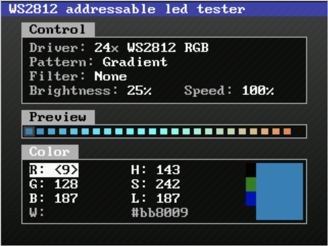
Controlling addressable LEDs with the LA104.
In the video after the break, [Gabriel] shows off some impressive radio tricks by adding a small CC1101 transceiver to the mix. This allows his modified LA104 to scan for and decode popular RF protocols in the 300 – 900 MHz range. His software even allows for the received packets to be modified and re-transmitted, which he demonstrates by pushing a fake temperature signal into a wireless weather station.
But that’s just the beginning. A perusal of the GitHub page for his replacement firmware shows just how many features have already been packed into this project. For example it can be used to control WS2812 LED strips, generate arbitrary PWM signals, log data from temperature sensors, interface with MIDI devices, and scan for I2C devices. Many of these functions can be controlled on the computer by utilizing a modern browser and WebUSB.
The replacement firmware that [Gabriel] has come up with for the LA104 is really an incredible accomplishment, and elevates an already intriguing piece of kit. Being able to pack all of these functions into something small and cheap enough you can toss into a bag is a very compelling prospect for hackers on the go.
There are many ways to update an embedded system in the field. Images can fly through the air one a time, travel by sneaker or hitch a ride on other passing data. OK, maybe that’s a stretch, but there are certainly a plethora of ways to get those sweet update bytes into a target system. How are those bytes assembled, and what are the tools that do the assembly? This is the problem I needed to solve.
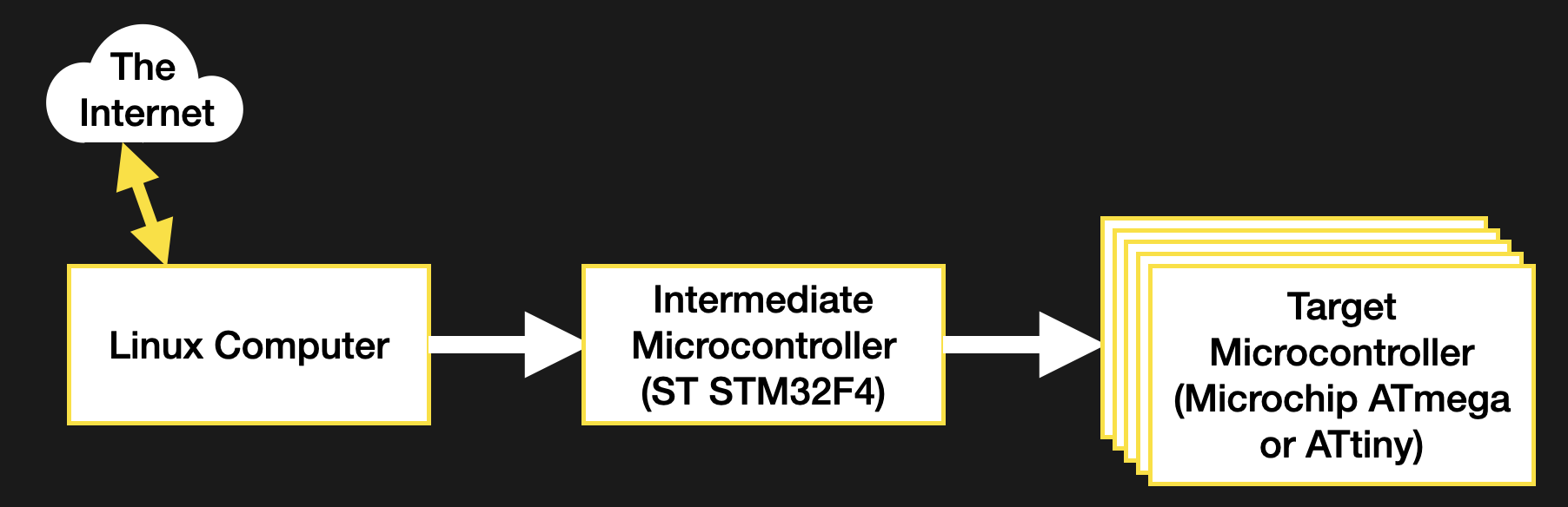
Recall, my system wasn’t a particularly novel one (see the block diagram below). Just a few computers asking each other for an update over some serial busses. I had chosen to bundle the payload firmware images into the binary for the intermediate microcontroller which was to carry out the update process. The additional constraint was that the blending of the three firmware images (one carrier and two payload) needed to happen long after compile time, on a different system with a separate toolchain. There were ultimately two options that fit the bill.
The system thirsty for an update
Edit The ELF
There’s more than one way to use the linker to stick binaries together — that’s its job after all. A typical compilation toolchain uses ld to string object files together, but there are other linker-adjacent tools which come in handy for playing havoc with the right kind of binary file. This method for bundling firmware images together will focus on a new tool in the GCC, objcopy.
To abuse the metaphor, objcopy is a bit of a utility knife for object file manipulation. The breadth of it’s functionally is wide but the specific thing we need here is the --update-section parameter, which allows us to replace a named section in an object file with another object file. So how do we get that section? That’s where a configuration file called a “linker script” comes in.
A detailed discussion of the usage of the linker script is out of scope here but for now let’s summarize it as, well, a script for the linker! A complete executable is composed of many different sections, and the linker script is what describes where they should go and how to refer to them. For instance, in a microcontroller the text section where the code-to-be-executed is stored is often placed in flash at an address where the micro will begin execution. The linker script is what describes the region where that data should go, and that it should be located in flash. We can use the same mechanism to inject a firmware payload into our image.
My first step was to describe two new sections, one for each new firmware image. The following segment shows the data section for the intermediate microcontroller, and the two payload sections I added below it.
/* Initialized data sections into "RAM" Ram type memory */
.data :
{
  . = ALIGN(4);
  _sdata = .; /* create a global symbol at data start */
  *(.data) /* .data sections */
  *(.data*) /* .data* sections */

  . = ALIGN(4);
  _edata = .; /* define a global symbol at data end */

} >RAM AT> FLASH
/* Below this point are the sections I added */
.payload1 :
{
  . = ALIGN(4);
  BYTE(0x0);
  payload1End = .;
} >FLASH

.payload2 :
{
  . = ALIGN(4);
  BYTE(0x0);
  payload2End = .;
} >FLASH
This is a little cryptic, but it should be clear that payload1 and payload2 are both specially delineated sections which are to be placed in flash. With these defined, the linker will take care of ensuring the symbols are defined, the sections are large enough, and that they won’t overlap anything else. They will float along relative to their neighbors in the same order, keeping these two sections at the end of flash and the *end symbols at the end of their respective sections.
To access these sections at runtime we can refer to the named symbols payload1/payload1End and payload2/payload2End as extern symbols in our C source, but they’re also visible in the compiled binary. For this we need to use the Executable Linked File (ELF) that the linker produces as its final output. In my case this was the default output and was converted from an ELF to a binary to flash to the microcontroller. Depending on your platform this may or may not be the case.
The ELF file contains everything needed to run your program, including all the metadata and symbols the linker has at link time, whereas the binary may have these stripped out. If they are present than tools like objcopy can refer to them. At this point injecting the firmware is just a single well-formed command away. Convert the bin payload in question into an object file then use objcopy to inject it into the final binary like so
objcopy uses the same tricks as the linker to make everything fit and moves our symbols around as needed to mark the sections in question. Now the running firmware can get the size by subtracting the address of the start and end symbols, and refer to the payload memory as starting at the start address. Easy!
So why wasn’t this my final method for injecting payload firmwares? It requires a copy of objcopy that knows how to handle ELFs of the target architecture. In my use case I didn’t have such a toolchain available in the right place to make use of it, so I moved onto the next method.
1337 H4X: The Binary Edit
If nothing more clever works, a binary is just a file to be edited. It’s not particularly elegant, but modifying the binary directly is nothing if not universally applicable, so long as you know the details of the file going under the knife.
Let’s start with attaching multiple binary files together. This turns out to be extremely straightforward; just concatenate them! The command looks like
It’s that easy! I needed to get the combined file into the intermediate microcontroller, which turned out to be similarly straightforward. The microcontroller’s flashing tool will happily write the combined firmware to the device, placing the payload files in the right address. But how does the running firmware know where to look to extract the payloads? And how does it know know how large they are? For that we need to turn back to our friend the linker.
Keep in mind the files we have to work with are the final binary images without any of the embedded metadata in the previous method. And even if they were, this process needed to work without the processor-specific toolchain on hand. So what to do? When editing the ELF, we used the linker script to describe a new section in flash. We can use the same trick here to create a special “end of firmware” section and symbol. As long as the linker script orients it as the last element of the image to be written to flash, it will be guaranteed to float along and always stay at the end as the rest of the firmware grows and shrinks during development.
Now that we have an end of firmware flag we the puzzle can be solved. For simplicity, in this section I chose to place 8 magic bytes (as two uint32_t‘s) describing the size of the images to follow. In the future, if I need more flexibility I could place a file with a JSON object, some serialized msgpack, or anything else there instead. The final image looks like
But what happens if there is no payload appended? The intermediate microcontroller needs a way to tell if there is anything out there in the wilds of flash to search for. Erased flash might work (it should always read as 0xFF), but if the flashed image shrinks and I was unluckily on an erase boundary there might be valid-looking garbage data there instead of a fresh field of 0xFFs. To avoid this I turned to the linker once again.
The linker script allows for the definition of hardcoded bytes or byte patterns to fill a region. So I added two 4 byte check values in a region after the end of firmware flag. At runtime the firmware loads the payload firmware sizes from the end of firmware offset and compares them to the check values. If they match, it assumes no payload is present. The section defined in the linker script looks like this
When the firmware is being bundled together, I truncate the main firmware file and remove the final 8 bytes to remove this section. Then I create a file containing the two payload sizes and concatenate it on. The linker guarantees that the last 8 bytes are always the check values (which can be confirmed with a hexdump). At this point the command looks like
The last piece of the puzzle is building that 8 byte size file. I wanted to embed the size as raw byte values (not ASCII) to force them into a constant size. For this we must reach all the way back to the beginning of this journey to again find xxd. Previously I used xxd to convert from a binary file to hex (in the form of C source), but the tool works in reverse as well, converting from a hex file to a binary. It’s not too picky, so all we need to give it is the starting address of the “hex file” to convert, then the series of bytes it should consume to produce the binary output file. All together that looks like
There we go! Two more methods for editing binary files. Between these and the first two options described, most use cases should be covered. Most of these techniques should serve well for any assets which need to combined; think adding sound effects or images to a system without external storage to hold them.
Hopefully you now feel empowered to slice and dice your way to binary payload victory, no matter the geometry in question.
Looking to give himself a competitive edge, racer [Douglas Hedges] wanted to come up with a system that could give him real-time feedback on how his current performance compared to his previous fastest lap time. Armed with a Raspberry Pi and some Python libraries, he set out to add a simple telemetry system to his car. But as is often the case with these kind of projects, things just started snowballing from there.
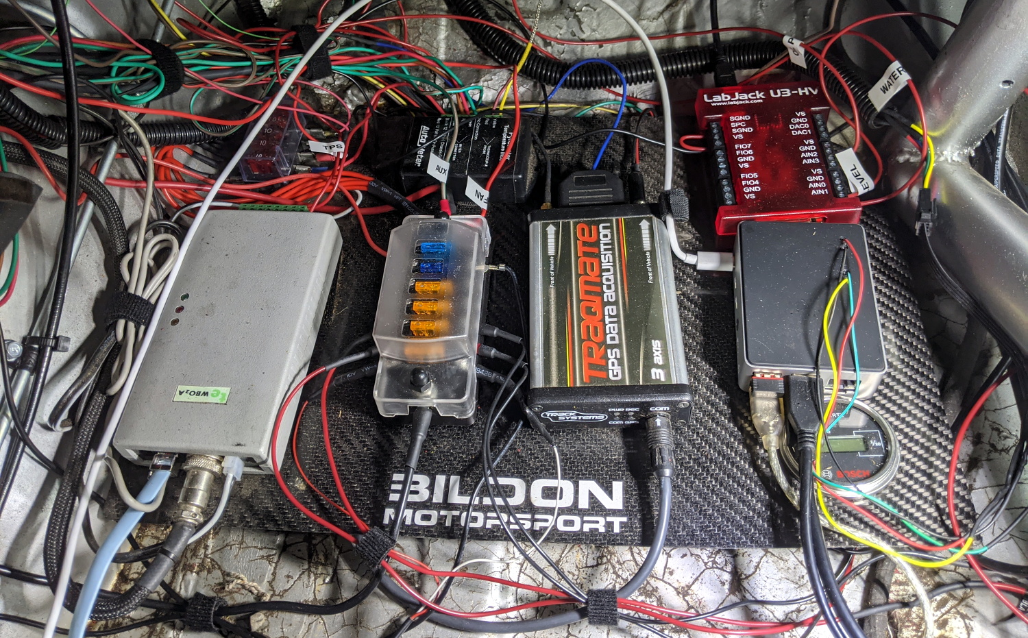
The Raspberry Pi based data acquisition system.
At the most basic level, his system uses GPS position and speed information to light up a strip of RGB LEDs on the dashboard: green means he’s going faster than the previous best lap, and red means he isn’t. Any interface more complex than that would just be a distraction while he focuses on the track. But that doesn’t mean the Raspberry Pi can’t collect data for future review after the race is over.
With the basic functionality in place, [Douglas] turned his attention to collecting engine performance data. It turned out the car already had some pre-existing equipment for collecting metrics such as the air-fuel ratio and RPM, which he was able to connect to the Raspberry Pi thanks to its use of a well documented protocol. On top of that he added a Labjack U3 data acquisition system which let him pull in additional information like throttle position and coolant temperature. Grafana is used to visualize all of this data after the race, though it sounds like he’s also considering adding a cellular data connection vehicle data can be streamed out in real-time.
Created for the Disobey 2020 hacker conference in Finland, this Blade Runner inspired communications terminal isn’t just for decoration. It was part of an interactive game that required attendees to physically connect their conference badges up and “call” different characters with the functional keypad on the front of the unit.
[Purkkaviritys] was in charge of designing the 3D printed enclosure for the device, which he says takes an entire 2 kg roll of filament to print out. Unfortunately he wasn’t as involved in the electronics side of things, so we don’t have a whole lot of information about the internals beyond the fact that its powered by a Raspberry Pi 4, features a HyperPixel 4.0 display, and uses power over Ethernet so it could be easily set up at the con with just a single cable run.
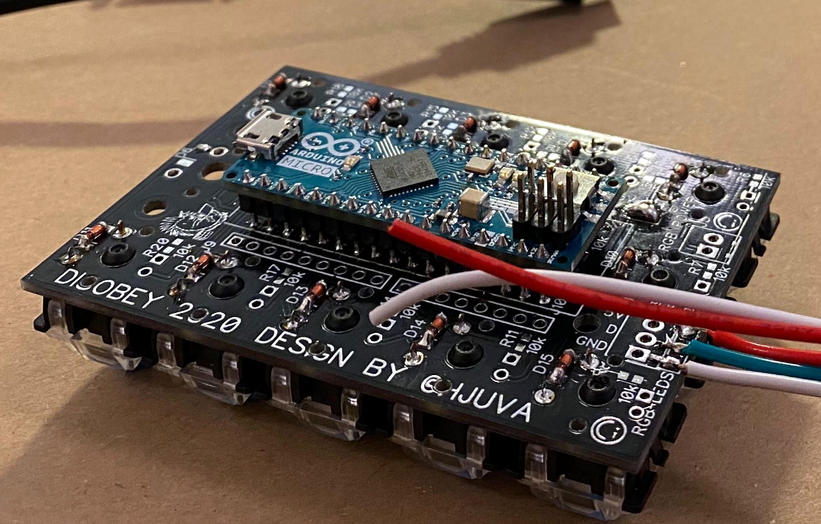
A look at the custom keypad PCB.
The keypad is a custom input device using the Arduino Micro and Cherry MX Blue switches with 3D printed keycaps to get that chunky payphone look and feel. [Purkkaviritys] mentions that the keypad is also responsible for controlling the RGB LED strips built into the sides of the terminal, and that the Raspberry Pi toggles the status of the Caps, Scroll Lock, and Num Lock keys to select the different lighting patterns.
Naturally we’d like to see more info on how this beauty was put together, but given that it was built for such a specific purpose, it’s not like you’d really need to duplicate the original configuration anyway. Thanks to [Purkkaviritys] you have the STL files to print off our own copy of the gloriously cyberpunk enclosure, all you’ve got to do now is figure out how to make video calls with it.
Created for the Disobey 2020 hacker conference in Finland, this Blade Runner inspired communications terminal isn’t just for decoration. It was part of an interactive game that required attendees to physically connect their conference badges up and “call” different characters with the functional keypad on the front of the unit.
[Purkkaviritys] was in charge of designing the 3D printed enclosure for the device, which he says takes an entire 2 kg roll of filament to print out. Unfortunately he wasn’t as involved in the electronics side of things, so we don’t have a whole lot of information about the internals beyond the fact that its powered by a Raspberry Pi 4, features a HyperPixel 4.0 display, and uses power over Ethernet so it could be easily set up at the con with just a single cable run.
A look at the custom keypad PCB.
The keypad is a custom input device using the Arduino Micro and Cherry MX Blue switches with 3D printed keycaps to get that chunky payphone look and feel. [Purkkaviritys] mentions that the keypad is also responsible for controlling the RGB LED strips built into the sides of the terminal, and that the Raspberry Pi toggles the status of the Caps, Scroll Lock, and Num Lock keys to select the different lighting patterns.
Naturally we’d like to see more info on how this beauty was put together, but given that it was built for such a specific purpose, it’s not like you’d really need to duplicate the original configuration anyway. Thanks to [Purkkaviritys] you have the STL files to print off our own copy of the gloriously cyberpunk enclosure, all you’ve got to do now is figure out how to make video calls with it.
Created for the Disobey 2020 hacker conference in Finland, this Blade Runner inspired communications terminal isn’t just for decoration. It was part of an interactive game that required attendees to physically connect their conference badges up and “call” different characters with the functional keypad on the front of the unit.
[Purkkaviritys] was in charge of designing the 3D printed enclosure for the device, which he says takes an entire 2 kg roll of filament to print out. Unfortunately he wasn’t as involved in the electronics side of things, so we don’t have a whole lot of information about the internals beyond the fact that its powered by a Raspberry Pi 4, features a HyperPixel 4.0 display, and uses power over Ethernet so it could be easily set up at the con with just a single cable run.
A look at the custom keypad PCB.
The keypad is a custom input device using the Arduino Micro and Cherry MX Blue switches with 3D printed keycaps to get that chunky payphone look and feel. [Purkkaviritys] mentions that the keypad is also responsible for controlling the RGB LED strips built into the sides of the terminal, and that the Raspberry Pi toggles the status of the Caps, Scroll Lock, and Num Lock keys to select the different lighting patterns.
Naturally we’d like to see more info on how this beauty was put together, but given that it was built for such a specific purpose, it’s not like you’d really need to duplicate the original configuration anyway. Thanks to [Purkkaviritys] you have the STL files to print off our own copy of the gloriously cyberpunk enclosure, all you’ve got to do now is figure out how to make video calls with it.
When working with hardware, whether a repair or a fresh build, it’s often necessary to test something. Depending on what you’re working with, this can be easy or a total pain if you can’t get the right signal to the right place. To eliminate this frustrating problem, [WilkoL] built a useful pulse generator for use in the lab.
[WilkoL] notes that historically, the job of generating pulses of varying length and frequency would be achieved with a smattering of 555 timers. While this is a perfectly cromulent way to do so, it was desired to take a different approach for the added flexibility modern hardware can offer. The pulse generator is instead built around an STM8 microcontroller; an unusual choice in this era, to be sure. [WilkoL] specified the part for its incredibly low cost, and highly capable timer hardware – perfect for the job.
Combined with an ST7735 TFT LCD screen, and programmed in bare metal for efficiency’s sake, the final project is installed in a project box with controls for frequency and pulse length – no more, no less. Capable of pulse lengths from 250 ns to 90 s, and frequencies from 10 mHz to 2 MHz, it’s a tool that should be comfortable testing everything from servos to mechanical counters.
These days, everything’s got a clock in it, and a good proportion of those clocks are automatically syncronized to high-accuracy Internet time servers. Back in the past, things weren’t so easy. Often, institutions that required accurate time would use a single highly-accurate primary clock to drive a series of secondary clocks around a facility. Without the primary clock, the secondary clock has no signal to drive it. [Oleksii Samorukov] had just such a clock, and whipped up a controller to stand in for timekeeping duty.
The secondary clock is in question is a Pragotron PJ 27, which requires regular 12V signals of alternating polarity in order to keep time. To handle this job, [Oleksii] decided to use an ESP32 in combination with a L298N motor controller. The L298N is an H-bridge driver chip, allowing it to easily supply the 12V signals in alternating polarities where required. To ensure the system keeps accurate time, the ESP32 regularly queries an NTP time server over WiFi.
It’s a tidy build, and one that brings this attractive 1960s timepiece into the modern era. We’d love to have such a stylish, well-built clock in our own home, too. Of course, if you want really accurate time, building a GPS clock is a great option, too!
Once you move away from the usual software defined radio (SDR) dongles, you have only a few choices unless you want to drop some serious cash. One common hobby-grade SDR is the KiwiSDR. This popular unit runs Linux and can receive up to 30 MHz. The platform uses a dedicated A/D converter, an FPGA, and BeagleBone computer. Success of course breeds imitators, and especially when you have an open source design like the Kiwi, you are going to find similar devices with possibly different end goals. That’s how the RaspberrySDR came to be. This is a very similar unit to the KiwiSDR but it uses a Raspberry Pi, along with a handful of other differences. What’s different? [KA7OEI] tells us in a recent blog post.
Other than the obvious difference of the computer and all that it entails, the RaspberrySDR has a higher speed A/D (125 MHz vs 66 MHz) and 16-bits of resolution instead of the Kiwi’s 14 bits. This combines to give the Raspberry a wider receive range (up to 60 MHz) and — in theory — better performance in terms of dynamic range and distortion.
[KA7OEI] measures a few key parameters on both devices and arrived at some surprising conclusions. The Kiwi appears to boost signals near its cutoff frequency to compensate for losses in the system. The Raspberry — using adapted software — looks as though it does the same trick, but does it around the Kiwi’s cutoff frequency, which is lower. Probably a software fix could take care of that, of course.
There are also tests of image rejection and front-end overloading. The tests revealed a few problems with signal strength measurement and some other problems with the RaspberrySDR. The biggest issue, though, was that the 16-bit A/D didn’t seem to have better performance. Without proper design, throwing more bits at a problem isn’t always helpful and this appears to be a good example of that.
In the end, the Raspberry looks like a cheap clone of the Kiwi with some benefits, but also some drawbacks. The blog post also covers some open source issues where Kiwi is now saying some parts of their code will only be binary in the future and there has been some difficulty finding all of the Raspberry’s files. If you are looking to buy one, you might not find the name “raspberrysdr” but [KA7OEI] suggests searching for “New 16bit 62M real-time bandwidth network shared SDR receiver” which does turn up some results.
Knowing how WiFi networks can be attacked is a big part of properly securing them, and the best way to learn about it is to (legally) run some attacks. [Matt Agius] has been going down the WiFi-cracking rabbit hole, and in the process created Pwnagotchi Tools to automate the actual password cracking part.
The first step in cracking a WiFi network is to record the handshake that gets exchanged when a client connects to an access point. This has been made very simple thanks to Pwnagotchi, which turns a Raspberry Pi into an automated handshake collection tool and Pwnagothi Tools helps to automate the steps that follow. It downloads the handshakes (pcap files) from the pwnagotchi, and converts it to pmkid/hccapx files to use with the hashcat password recovery tool. Hashcat scripts can then be generated for the actual cracking using any of the attacks that [Matt] has compiled. WPA/WPA2 is slow to crack and requires a lot of processing power, so [Matt] also added the option to automatically provision AWS GPU instances to run the cracking task in the cloud. It also keeps track of the status of each of the handshakes being cracked.
As wireless networks and IoT devices become more pervasive, it’s important to know the dangers, and how to protect against them. WiFi and Bluetooth security is probably the easiest to learn about, but other networks are just as vulnerable when an RTL-SDR is used. Another option Flipper Zero, a hacking gadget for Sub-1 GHz networks inspired by Pwnagotchi, which recently hit $4.8 million in its Kickstarter campaign.
When you’re building advanced rockets as BPS.Space are, an unreliable launchpad is the something you really don’t want to be struggling with. [Joe Barnard] is working on a model rocket that can land vertically under its own power, like the Falcon 9, and has upgraded his launchpad in the process. A lot of thought and hard-earned experience has gone into its design, and the video after the break is a fascinating look the engineering process.
[Joe]’s rockets don’t use guide rods and fins for stabilization in the way most amateur rockets do, but instead have thrust vectoring motor mounts and reaction wheels for active stabilization during launch and flight. The rockets are clamped to the launchpad right up to ignition, and then need to release quickly and reliably. His previous clamps looked very cool, but suffered from high friction forces during release, and the integrated covers prevented easy inspection. These were replaced by much simpler spring-loaded clamp held in place by a small locking bar, which is knocked out by a servo to release the clamp. It also has no static friction, since it moves up and away from the clamping surfaces on the rocket.
The launch pad also features a ATSAMD21 based launch computer named Impulse, which at the most basic level controls the igniter, clamps, buzzer and indicator lights. It also has a number of inputs and outputs to allow for expansion. [Joe] experienced a number of inexplicable failures of rocketry electronics in the past, but believes he has finally tracked down the culprit: Tennessee humidity. He has since started conformal coating all his electronics.
The launchpad itself is made from plywood, so to protect it from the hot exhaust it has in integrated flame trench. This was made from 1 inch steel plumbing components, and directs most of the exhaust out of one side of the platform. It can also be reconfigured to allow a three core rocket like a Falcon Heavy to be launched.
It’s incredible to see how far BPS.Space has come in the past four years, with the engineering complexity and video production quality increasing in leaps and bounds. Earlier this year we covered on of [Joe]’s other projects, a silo-launched rocket named Thoomp.
Sometimes a problem is more important than its solution. Humans love to solve mysteries and answer questions, but the most rewarding issues are the ones we find ourselves. Take [Surjan Singh], who wanted to see if he could calculate the weight of his Saab 96. Funny enough, he doesn’t have an automobile scale in his garage, so he had to concoct a workaround method. His solution is to multiply the pressure in his tires with their contact patch. Read on before you decide this is an imperfect idea.
He measures his tires with a quality gauge for the highest accuracy and pressurizes them equally. Our favorite part is how he measures the contact patch by sliding a couple of paper pieces from the sides until they stop and then measures the distance between them. He quickly realizes that the treads didn’t contact the floor evenly, so he measures them to get a better idea of the true contact area. Once he is satisfied, he performs his algebra and records the results, then drives to some public scales and has to pay for a weigh. His calculations are close, but he admits this could be an imprecise method due to an n-of-one, and that he didn’t account for the stiffness of the tire walls.
Sometimes a problem is more important than its solution. Humans love to solve mysteries and answer questions, but the most rewarding issues are the ones we find ourselves. Take [Surjan Singh], who wanted to see if he could calculate the weight of his Saab 96. Funny enough, he doesn’t have an automobile scale in his garage, so he had to concoct a workaround method. His solution is to multiply the pressure in his tires with their contact patch. Read on before you decide this is an imperfect idea.
He measures his tires with a quality gauge for the highest accuracy and pressurizes them equally. Our favorite part is how he measures the contact patch by sliding a couple of paper pieces from the sides until they stop and then measures the distance between them. He quickly realizes that the treads didn’t contact the floor evenly, so he measures them to get a better idea of the true contact area. Once he is satisfied, he performs his algebra and records the results, then drives to some public scales and has to pay for a weigh. His calculations are close, but he admits this could be an imprecise method due to an n-of-one, and that he didn’t account for the stiffness of the tire walls.
Strong opinions exist on both sides about OpenSCAD. The lightweight program takes megabytes of space, not gigabytes, so many people have a copy, even if they’ve never written a shape. Some people adore the text-only modeling language, and some people abhor the minimal function list. [Johnathon ‘Zalo’ Selstad] appreciates the idea but wants to see something more robust, and he wants to see it in your browser. His project CascadeStudio has a GitHub repo and a live link so you can start tinkering in a new window straight away.
We’re going to assume that anyone reading past this point is familiar with this type of modeling.
At the first keystroke, it is evident that CascadeStudio is different from OpenSCAD. For starters, tooltips reveal that formatting is a little different. A cone in OpenSCAD uses the cylinder() function while CascadeStudio insists that Cylinders() are the same diameter at the top and bottom, but a Cone() tapers. You may also notice the capital letters for CascadeStudio. Minor differences of this scale mean that anyone familiar with one may have speedbumps with the other, but not roadblocks.
In our opinion, the biggest boon to CascadeStudio is that you can send someone a URL, and they will get access to a fully-functional copy. You cannot simultaneously edit like a Google document, but it is conceivable to store a 3D model within a QR code, or an RFID tag, possibly without a URL shortener. Each time you refresh the rendered model by pressing F5, the URL updates, so it is possible to create dated savepoints with your browser bookmarks. You can save and load JSON files if you prefer to download your files, and you can export STEP, STL, and OBJ files for your printer.
Please tell us what you think of CascadeStudio below, and if this changed your mind about text-based modeling. We’ve seen this parametric workhorse tackle everyday tasks like container boxes to high-security keys.
The Nintendo 64 made a big splash when it launched in 1996, not least of all for its innovative controller. Featuring a never-before-or-since seen trident design, and with an analog stick smack bang in the center, it changed what gamers expected from consoles from that day forward. Of course, those controllers are now much worse for wear, and technology has moved on somewhat. The latest development from [Ryzee119] aims to rectify this somewhat.
The result of that work is USB64, a tool designed to allow the use of USB controllers on the Nintendo 64. Using a Teensy 4.1, it builds upon earlier work to get the Xbox 360 controller working on the platform. However, the feature set has been greatly expanded, covering almost any use case imaginable. Mempacks are now efficiently emulated, and save files can be backed up to a PC via SD card. Additionally, the GameBoy Transferpak is emulated, meaning data can be transferred between GameBoy ROMs on an SD card and games on the N64. Even the N64 mouse is supported, and can be emulated with a regular USB mouse. Capable of doing all this for all four players, work is ongoing to increase the number of compatible aftermarket controllers for the utmost flexibility. [Ryzee119] also coded up a useful test ROM for the N64, which is invaluable when debugging controller hardware.
Fiber optics are a great way to transfer huge quantity of data at lightning speed. Thanks to the property of total internal reflection, which allows light to flow through a glass fiber like fluid through a pipe, they can be used for communications at long distances and form the backbone of modern communication networks. However, water is also able to pull off the total internal reflection party trick, and [Mike Kohn] decided to see if it could be used as a communication medium, too.
The experimental setup consists of an ATTiny85 that receives signals over its serial port, and outputs the received bits by flashing an LED. This LED is attached to a plastic tube filled with water. On the receiving end, another ATTiny85 reads the voltage level of a photodiode placed in the other end of the tube. When the ADC detects voltage over a certain level, it toggles a pin connected to the serial RX pin.
Hooking the setup to a pair of terminals, [Mike] was able to successfully transmit 9600 baud serial data through a tube full of water with just an LED and a small microcontroller. To verify the success, he ran the test again with an air-filled tube instead, which failed. In doing so, he proved that the water was doing the work.
Once upon a time, 3D printing was more of a curiosity than a powerful tool, with many printing trinkets and tchotchkes rather than anything of real use. However, over the years as technology and techniques have progressed, we now see more application-ready builds. This water pump from [Let’s Print] is a great example.
The pump consists of two major pieces – a drive unit, and an impeller. The drive unit consists of a gearbox that combines the power of eight electric motors, driving a single shaft. This is all achieved with striking yellow ABS gears in a black housing. The build video does a great job of explaining how to make the project work with different motors, and how to properly use the bolt adjuster to set the backlash on the gear train. The drive unit is then used to turn a 3D-printed impeller pump which is capable of delivering a great deal of water very quickly.
When fired up, the leaky assembly makes an awful racket and a huge mess, but sure as heck shifts a lot of water while it does so. Watching the water spray off the gears as it leaks through the bearings is a great sight, and it’s clear that the device works well. We’d love to see a cost and performance analysis of this pump versus a commercial offering.
While it’s certainly not the most rugged build, it’s a fun one that nevertheless gets the job done. We’d love to see this running a foam machine or a classic slip and slide. Video after the break.