ESP32 Spectrum Analyzer Taps Into Both Cores

We probably don’t need to tell the average Hackaday reader that the ESP32 is a powerful and extremely flexible microcontroller. We’ve seen some incredible projects using this affordable chip over the last few years, and by the looks of it, the best is yet to come. That’s because it always takes some time before the community can really figure out how to get the most out of a piece of hardware.

Take for example the Bluetooth audio player that [squix] was recently working on. Getting the music going was no problem with the esp32-a2dp library, but when he wanted to add some visualizations the audio quality took a serious hit. Realizing that his Fast Fourier transform (FFT) code was eating up too much processor power, it seemed like a great time for him to explore using the ESP32’s second core.

[squix] had avoided poking around with the dual-core nature of the ESP32 in the past, believing that the second core was busy handling the WiFi communication. But by using the FreeRTOS queue system, he wrote some code that collects audio data with one core and runs the actual FFT magic on the other. By balancing the workload like this, he’s able to drive the array of 64 WS2812B LEDs on the front of the Icon64 seen in the video after the break.

Even if you’re not terribly interested in running your own microcontroller disco, this project may be just the example you’ve been waiting for to help get your mind wrapped around multitasking on the ESP32. If you want to master a device with this many tricks up its sleeve, you’ll need all the help you can get.

source https://hackaday.com/2020/12/10/esp32-spectrum-analyzer-taps-into-both-cores/

The Macro Keyboard Is On Deck

The idea of a reconfigurable macro keyboard is a concept that has been iterated on by many all the way from custom DIY keypads to the polarizing TouchBar on MacBooks. The continual rise of cheap powerful microcontrollers with Wi-Fi and 3D printers makes rolling your own macro keyboard easier every year. [Dustin Watts] has joined the proverbial club and built a beautiful macro pad called FreeTouchDeck.

We’ve seen macro keyboards that use rotary encoders to cycle through different mappings for the keys. FreeTouchDeck has taken the display approach and incorporates a touch screen to offer different buttons. [Dustin] was inspired by a similar project called FreeDeck, which offers six buttons each with a small screen. FreeTouchDeck is powered by an ESP32 and drives an ILI9488 touch screen with an XPT2046 touch controller. This means that FreeTouchDeck can offer six buttons with submenus and all sorts of bells and whistles. A connection to the computer is done by emulating a Bluetooth keyboard. By adding a configuration mode that starts a web server, FreeTouchDeck allows easy customization on the fly.

[Dustin] whipped up a quick PCB that makes it easy to solder the ESP32 and the TFT together, but a breadboard works just fine. Gerbers for that are available on GitHub. To wrap it all up, a nice 3D printed shell encloses the whole system in a clean, tidy way. The code, documentation, and case designs are all on his GitHub.

Thanks [Dustin] for sending this one our way!

source https://hackaday.com/2020/12/10/the-macro-keyboard-is-on-deck/

A Walking Rover Destined Explore Your Fridge Door

It’s usually the simple ideas that sprout bigger ones, and this was the case when we saw [gzumwalt]’s single-motor walking robot crawling up a fridge door with magnets on its feet. (Video, embedded below.)

The walking mechanism consists of an inner foot and two outer feet, connected by three sets of rotating linkages, driven by a single geared motor. The feet move in a leapfrog motion, in small enough steps that the center of mass always stays inside the foot area, which keeps it from tipping over. Besides the previously mentioned ability to crawl around on a vertical magnetic surface, it’s also able to crawl over almost any obstacle shorter than its step length. A larger version should also be able to climb stairs.

As shown, this robot can only travel in a straight line, but this could be solved by adding a disc on the bottom of the inner foot to turn the robot when the outer feet are off the surface. Add some microswitch feelers and an Arduino, and it can autonomously explore your fridge without falling off. Maybe we’ll get around to building it ourselves, but be sure to drop us a tip if you beat us to it!

[gzumwalt] is a master of 3D printed devices like a rigid chain and a domino laying robot. The mechanism for this robot was inspired by one design from [thang010146]’s marvelous video library of mechanisms.

source https://hackaday.com/2020/12/10/a-walking-rover-destined-explore-your-fridge-door/

A Relay-Based Pseudorandom Number Generator

There are a great variety of ways to build a random number generator, and similarly many ways to generate numbers that appear random, but in a pure mathematical sense generally aren’t. [Daniel Valuch] built a Christmas decoration that does the latter, displaying the results on an attractive flashing ornament.

The build relies on a 16-bit linear feedback shift register, or LFSR. The LFSR generates a stream of numbers, with each number dependent on the previous state of the register. Thus, the numbers generated are pseudorandom, not truly random, and depend on the initial seed value of the system. [Daniel] built the shift register using relays, which create a lovely clacking sound as the register operates, and LEDs, which glow depending on the values in the register.

The result is a cute Christmas ornament that blinks in a deterministic fashion, and has a great old-school look due to the exposed copper of the PCB and the retro LED colors used. The project also serves as a great way to learn about shift registers and basic relay logic, though the latter is rarely used these days for serious purposes. We’ve covered the topic before, too. Video after the break.

source https://hackaday.com/2020/12/09/a-relay-based-pseudorandom-number-generator/

A PCB Diary

[Gijs Gieskes] has made another eye-catching PCB wonder, this time a diary built from several circuit boards which are assembled into a book, not unlike a PC/104 system. But with [Gijs]’s system you can easily open the stack-up to access single boards without disassembling the whole thing. We don’t see brass piano hinges on PCB assemblies very often, but [Gijs]’s PCB designs are anything but conventional. Hint: if you wanted to recreate this technique using more ordinary hardware, you can find hinged PCB standoffs from various suppliers.

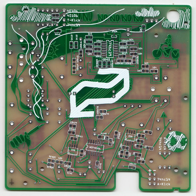
Bicycle, soccer ball, smoke on the “No no no no no…” PCB

Apparently it’s more than a passive piece of art.  Each board has several circuits, some of which (all?) are functioning is ways not clearly described, which seems to be intentional. According to his build log, different things happen when you mix and match the inter-board ribbon cables in various ways. We are told in the instructions “to just try and see what happens”. No schematics are posted, but there is a partial description of the circuits in the manual and parts on the two-layer boards are well-labeled. Although after spot checking a few circuits board photos, we’d guess that no small number of traces, and perhaps some parts, are wild goose chases.

The project claims to be a diary for the years 2018 and 2019, but we will leave it as an exercise for the reader to interpret the messages that [Gijs] has embedded into this fascinating piece. We have written about several of his projects over the years, such as this crazy bent Casio SK-1 from all the way back in 2005. And before dismissing this “book” style of circuit board stack-up as only for artists, check out this teardown of a Soyuz clock we covered back in January.

source https://hackaday.com/2020/12/09/a-pcb-diary/

A PCB Diary

[Gijs Gieskes] has made another eye-catching PCB wonder, this time a diary built from several circuit boards which are assembled into a book, not unlike a PC/104 system. But with [Gijs]’s system you can easily open the stack-up to access single boards without disassembling the whole thing. We don’t see brass piano hinges on PCB assemblies very often, but [Gijs]’s PCB designs are anything but conventional. Hint: if you wanted to recreate this technique using more ordinary hardware, you can find hinged PCB standoffs from various suppliers.

Bicycle, soccer ball, smoke on the “No no no no no…” PCB

Apparently it’s more than a passive piece of art.  Each board has several circuits, some of which (all?) are functioning is ways not clearly described, which seems to be intentional. According to his build log, different things happen when you mix and match the inter-board ribbon cables in various ways. We are told in the instructions “to just try and see what happens”. No schematics are posted, but there is a partial description of the circuits in the manual and parts on the two-layer boards are well-labeled. Although after spot checking a few circuits board photos, we’d guess that no small number of traces, and perhaps some parts, are wild goose chases.

The project claims to be a diary for the years 2018 and 2019, but we will leave it as an exercise for the reader to interpret the messages that [Gijs] has embedded into this fascinating piece. We have written about several of his projects over the years, such as this crazy bent Casio SK-1 from all the way back in 2005. And before dismissing this “book” style of circuit board stack-up as only for artists, check out this teardown of a Soyuz clock we covered back in January.

source https://hackaday.com/2020/12/09/a-pcb-diary/

A PCB Diary

[Gijs Gieskes] has made another eye-catching PCB wonder, this time a diary built from several circuit boards which are assembled into a book, not unlike a PC/104 system. But with [Gijs]’s system you can easily open the stack-up to access single boards without disassembling the whole thing. We don’t see brass piano hinges on PCB assemblies very often, but [Gijs]’s PCB designs are anything but conventional. Hint: if you wanted to recreate this technique using more ordinary hardware, you can find hinged PCB standoffs from various suppliers.

Bicycle, soccer ball, smoke on the “No no no no no…” PCB

Apparently it’s more than a passive piece of art.  Each board has several circuits, some of which (all?) are functioning is ways not clearly described, which seems to be intentional. According to his build log, different things happen when you mix and match the inter-board ribbon cables in various ways. We are told in the instructions “to just try and see what happens”. No schematics are posted, but there is a partial description of the circuits in the manual and parts on the two-layer boards are well-labeled. Although after spot checking a few circuits board photos, we’d guess that no small number of traces, and perhaps some parts, are wild goose chases.

The project claims to be a diary for the years 2018 and 2019, but we will leave it as an exercise for the reader to interpret the messages that [Gijs] has embedded into this fascinating piece. We have written about several of his projects over the years, such as this crazy bent Casio SK-1 from all the way back in 2005. And before dismissing this “book” style of circuit board stack-up as only for artists, check out this teardown of a Soyuz clock we covered back in January.

source https://hackaday.com/2020/12/09/a-pcb-diary/

PET 2001 Emulator on $2 of Hardware

Since the late 60s, Moore’s law has predicted with precision that the number of semiconductors that will fit on a chip about doubles every two years. While this means more and more powerful computers, every year, it also means that old computers can be built on smaller and cheaper hardware. This project from [Bjoern] shows just how small, too, as he squeezes a PET 2001 onto the STM32 Blue Pill.

While the PET 2001 was an interesting computer built by Commodore this project wasn’t meant to be a faithful recreation, but rather to test the video output of the Blue Pill, with the PET emulation a secondary goal. It outputs a composite video signal which takes up a good bit of processing power, but the PET emulation still works, although it is slightly slow and isn’t optimized perfectly. [Bjoern] also wired up a working keyboard matrix as well although missed a few wire placements and made up for it in the software.

With his own home-brew software running on the $2 board, he has something interesting to display over his composite video output. While we can’t say we’d emulate an entire PC just to get experience with composite video, we’re happy to see someone did. If you’d like to see a more faithful recreation of this quirky piece of computing history, we’ve got that covered as well.

source https://hackaday.com/2020/12/09/pet-2001-emulator-on-2-of-hardware/

CentOS is Dead, Long Live CentOS

On Tuesday, December 8th, Red Hat and CentOS announced the end of CentOS 8. To be specific, CentOS 8 will reach end of life at the end of 2021, 8 years ahead of schedule. To really understand what that means, and how we got here, it’s worth taking a trip down memory lane, and looking at how the history of Red Hat Enterprise Linux (RHEL), CentOS, and IBM are intertwined.

First, History

Red hat started way back in 1995, with the partnership between Bob Young and Marc Ewing. Ewing brought his nascent Linux distro, named Red Hat Linux after the fedora red lacrosse cap Ewing was known for wearing. Red Hat Linux quickly introduced a set of killer features, such as the Red Hat Package Manager (RPM), the Anaconda installer, and ELF binaries, to name a few. By 2003, Red Hat Linux was split into two separate distros, RHEL and Fedora Core. RHEL was the subscription-only distribution, while Fedora Core was the bleeding-edge distribution available for free. Just a note, I was running Fedora on my machines since before they dropped “Core” from the name.

The RHEL product, while open source, is only available for paid subscribers, or developers in non-production environments. Because it’s open source, there is nothing preventing a third party from removing the branding, and recompiling the packages for free. This is exactly what Gregory Kurtzer and the other founding members of CentOS did back in 2004. CentOS version 2 was the first such release, bringing an Enterprise Linux to the Community.

The next bit of history we have to cover was in 2009, when Lance Davis went missing from the project. This was a problem, because Davis held the project domain registrations, the donations fund, and some of the other intellectual property of the project. There was a possibility that this would kill the project, but Davis finally responded to a published open letter from the project, and agreed to hand over control. Crisis averted.

Becoming Respectable

In 2014, an important change was announced. Red Hat would officially sponsor CentOS. Several of the core CentOS team would go full time on the Red Hat payroll, Red Hat got a trio of seats on the governing board, and most importantly, the community was assured that “The CentOS Linux platform isn’t changing.” It wasn’t made entirely clear, but part of the deal included transferring the CentOS trademarks and IP to Red Hat for safe keeping.

This arrangement worked out well for years. CentOS 8 shipped September 2019, rapidly after RHEL 8, and CentOS Stream was announced and released as an early look at what was coming in the next minor update. CentOS Stream could be thought of as a polished beta channel.

IBM bought Red Hat in 2019. Part of the announcement was a promise that Red Hat would stay true to its Open Source roots, claiming that “Red Hat’s mission and unwavering commitment to open source will remain unchanged.” Even with such assurances, many users were concerned that the IBM acquisition would fundamentally alter the way Red Hat does businesses for the worse.

Where Are We Now

With this context in mind, the recent news is troubling. Many of us have deployed CentOS servers to production environments, trusting Red Hat’s promise that CentOS 8 would be supported through 2029. The Red Hat announcement means that those installs reach end of life after less than 2 years, with the only upgrade path being Centos Stream — AKA being a forced beta tester for RHEL. As you might imagine, the response from the community has not been positive. We feel betrayed and lied to. It’s unclear whether this decision was handed down from IBM, or was cooked up by Red Hat themselves. In any case, it’s become painfully clear that handing over control of CentOS was a terrible mistake.

For those of us who prefer RPM based systems, where does that leave us? Fedora is great, but the rapid development cadence is terrible for server deployment. OpenSUSE Leap is a rebuild of SUSE Linux Enterprise Server, much like CentOS, and is a viable option for new deployments.

In the comments on the CentOS announcement, Gregory Kurtzer asked for users and developers interested in a reboot to check in on one of his slack channels. Within 8 hours, over 250 of us showed up, wanting to make a CentOS replacement happen. I’ve talked directly with Gregory, and can confirm that a new community rebuild of RHEL is happening under the name Rocky Linux, in honor of one of another CentOS co-founder that has passed away. The plan is to support a direct transition path from CentOS to Rocky Linux.

Rocky Linux will be bug-for-bug compatible with RHEL. It will be CentOS as it was before the Red Hat takeover, just under a new name. I’m excited to see where the project goes, and hopeful to see an initial release in the following months. When it happens, we’ll be sure to tell you about it.

source https://hackaday.com/2020/12/09/centos-is-dead-long-live-centos/

Speaker Snitch Tattles on Privacy Leaks

A wise senator once noted that democracy dies with thunderous applause. Similarly, it’s also how privacy dies, as we invite more and more smart devices willingly into our homes that are built by companies that don’t tend to have our best interests in mind. If you’re not willing to toss all of these admittedly useful devices out of the house but still want to keep an eye on what they’re doing, though, [Nick Bild] has a handy project that lets you keep an eye on them when they try to access the network.

The device is built on a Raspberry Pi that acts as a middle man for these devices on his home network. Any traffic they attempt to send gets sent through the Pi which sniffs the traffic via a Python script and is able to detect when they are accessing their cloud services. From there, the Pi sends an alert to an IoT Arduino connected to an LED which illuminates during the time in which the smart devices are active.

The build is an interesting one because many smart devices are known to listen in to day-to-day conversation even without speaking the code phrase (i.e. “Hey Google” etc.) and this is a great way to have some peace-of-mind that a device is inactive at any particular moment. However, it’s not a foolproof way of guaranteeing privacy, as plenty of devices might be accessing other services, and still other devices have  even been known to ship with hidden hardware.

source https://hackaday.com/2020/12/09/speaker-snitch-tattles-on-privacy-leaks/

This Automated Wire Prep Machine Cuts and Strips the Wire

We’ve seen a fair number of automated wire cutting builds before, and with good reason: cutting lots of wires by hand is repetitive and carries the risk of injury. What’s common to all these automated wire cutters is a comment asking, “Yeah, but can you make it strip too?” As it turns out, yes you can.

The key to making this automated wire cutter and stripper is [Mr Innovative]’s choice of tooling, and accepting a simple compromise. (Video, embedded below.) Using just about the simplest wire strippers around — the kind with a diamond-shaped opening that adjusts to different wire gauges by how far the jaws are closed — makes it so that the tool can both cut and strip, and adapt to different wire sizes. The wire is fed from a spool to a custom attachment sitting atop a stepper motor, which looks very much like an extruder from a 3D-printer. The wire is fed through a stiff plastic tube into the jaws of the cutter. Choosing between cutting and stripping is a matter of aiming the wire for different areas on the cutter’s jaws, which is done with a hobby servo that bends the guide tube. The throw of the cutter is controlled by a stepper motor — partial closure nicks the insulation, while a full stroke cuts the wire off. The video below shows the build and the finished product in action.

Yes, the insulation bits at the end still need to be pinched off, but it’s a lot better than doing the whole job yourself. [Mr Innovative] has a knack for automating tedious manual tasks like this. Check out his label dispenser, a motor rotor maker, and thread bobbin winder.

source https://hackaday.com/2020/12/09/this-automated-wire-prep-machine-cuts-and-strips-the-wire/

Printed Circuits, 1940s Style

A presentation this month by the Antique Wireless Museum brought British engineer and inventor John Sargrove (1906-1974) to our attention. If you’ve ever peeked inside old electronics from days gone by, you’ve no doubt seen point-to-point wiring and turret board construction. In the 60s and 70s these techniques eventually made way for printed circuit boards which we still use today. But Mr Sargrove was way ahead of his time, having already invented a process in the 1930s to print circuits, not just boards, onto Bakelite. After being interrupted by the war, he formed a company Electronic Circuit Making Equipment (ECME) and was building broadcast radio receivers on an impressive automatic production line.

Mr. Sargrove’s passion was making radios affordable for everyone. But to achieve this goal, he had to make large advances manufacturing technology. His technique of embedding not only circuit traces, but basic circuit elements like resistors, capacitors, and inductors directly into the substrate foresaw techniques being applied decades later in integrated circuit design.  He also developed a compact vacuum tube which could be used in all circuits of a radio, called an “All-stage Valve“. Equally important was his futuristic automatic factory, which significantly reduced the number of factory workers needed to make radios from 1500 to 50. Having completed the radio design, he was also developing a television receiver using the same concepts. Unfortunately, ECME was forced into liquidation when a large order from India was cancelled upon declaration of independence in 1947.

You really must watch the video below. There are many bits and pieces of modern factory automation which we still use today, yet their implementation using 1940s techniques and technology is fascinating. Further reading links after the video. Thanks to [Mark Erdle] for the tip.


source https://hackaday.com/2020/12/08/printed-circuits-1940s-style/

Roll Your Own Tracking

The smartphone is perhaps the signature device of our modern lives. For most of the population it is never more than an arm’s length away, it’s on your person more than any other device in your life. Smartphones are packed with all sorts of radios and ways to communicate wireless. [Amine Mansouri] built an ESP8266 based tracking device that takes advantage of this.

Most WiFi-enabled devices will send out “probe requests” frames trying to search for the SSIDs they were connected to. These packets contain the device MAC address as well as the SSIDs you’ve connected to. Using about 12 components, [Amine] laid out a small board in Eagle. By putting the ESP8266 in monitor mode, the probe frames can be logged and uploaded. The code can be updated OTA making it easy to service while in the field.

With permission from his local library, eight repeater boards were scattered throughout the building to forward the probe packets to where the tracker could pick them up. A simple web interface was built that allows the library to figure out how many people are in the library and how often they frequent the premises.

While an awesome project with open-source code on Github, it is important to stress how important is it to get permission to do this kind of tracking. While some phones implement MAC randomization, there are still many out in the wild that don’t. While this is similar to another project that listens to radio signals to determine the coming and going of ships and planes, tracking people with this sort of granularity is in a different category altogether.

Thanks [Amine] for sending this one in!

source https://hackaday.com/2020/12/08/roll-your-own-tracking/

Home-Crafting A Motorcycle Throttle Hold

Cruise control is a common feature on automobiles, though less so in the motorcycle market. Given that continual throttle application on long rides can be a real pain in the wrist, many riders long for such a convenience. As a cheat solution, bolt-on locks that hold the throttle at a set position are available, though quality varies and generally they need to be activated by the throttle hand anyway. [Nixie] wanted a solution that would leave the right hand entirely free, and held, rather than locked, the throttle.

The device [Nixie] came up with is essentially a brake that fits inside the throttle handle and holds it in position. This is achieved with a mechanism that presses a pair of small brake shoes into the inside of the throttle, holding it from rotating back to neutral when the rider lets go. The brake is activated by a control on the left handlebar via a Bowden cable, allowing [Nixie] to activate the throttle hold on the highway and use the right hand to check pockets or simply rest.

It’s a tidy build, and [Nixie] does a great job of explaining the various design choices and the intricacies of the Bowden cable actuated mechanism. It’s anything but a one-size-fits-all build, but other enterprising machinists could certainly duplicate the design for other motorcycles without too many problems.

For those interested in more traditional cruise control, we’ve featured a teardown of a simplistic 90s Jeep system before. Video after the break.

source https://hackaday.com/2020/12/08/home-crafting-a-motorcycle-throttle-hold/

DevTerm Beats Cyberdeck Builders to the Punch

What makes a cyberdeck? Looking as though it came from an alternate reality version of the 1980s is a good start, but certainly isn’t required. If you’re really trying to adhere to the cyberpunk ethos, any good deck should be modular enough that it can be easily repaired and upgraded over time. In fact, if it’s not in a constant state of evolution and flux, you’ve probably done something wrong. If you can hit those goals and make it look retro-futuristic at the same time, even better.

Which is why the Clockwork DevTerm is such an interesting device. It ticks off nearly every box that the custom cyberdeck builds we’ve covered over the last couple years have, while at the same time being approachable enough for a more mainstream audience. You won’t need a 3D printer, soldering iron, or hot glue gun to build your own DevTerm. Of course if you do have those tools and the skills to put them to work, then this might be the ideal platform to build on.

With a full-sized QWERTY keyboard and widescreen display, the DevTerm looks a lot like early portable computers such as the TRS-80 Model 100. But unlike the machines it draws inspiration from, the display is a 6.8 inch 1280 x 480 IPS panel, and there’s no pokey Intel 8085 chip inside. The $220 USD base model is powered by the Raspberry Pi Compute Module 3, and if you need a little more punch, there are a few higher priced options that slot in a more powerful custom module. Like the Waveshare Pi CM laptop we recently looked at, there’s sadly no support for the newer CM4; but at least the DevTerm is modular enough that it doesn’t seem out of the question that Clockwork could release a new mainboard down the line. Or perhaps somebody in the community will even do it for them.

Speaking of which, the board in the DevTerm has been designed in two pieces so that “EXT Module” side can be swapped out with custom hardware without compromising the core functionality of the system. The stock board comes with extra USB ports, a micro USB UART port for debugging, a CSI camera connector, and an interface for an included thermal printer that slots into a bay on the rear of the computer. Clockwork says they hope the community really runs wild with their own EXT boards, especially since the schematics and relevant design files for the entire system are all going to be put on GitHub and released under the GPL v3.

They say that anything that sounds too good to be true probably is, and if we’re honest, we’re getting a little of that from the DevTerm. An (CPU BLOBs aside!) open hardware portable Linux computer with this kind of modularity is basically a hacker’s dream come true, and thus far the only way to get one was to build it yourself. It’s hard to believe that Clockwork will be able to put something like this out for less than the cost of a cheap laptop without cutting some serious corners somewhere, but we’d absolutely love to be proven wrong when it’s released next year.

source https://hackaday.com/2020/12/08/devterm-beats-cyberdeck-builders-to-the-punch/

SLA 3D Printed Vortex Cooled Rocket Engine

3D printing is an incredible tool for prototyping and development, but the properties of the materials can be a limiting factor for functional parts. [Sam Rogers] and colleagues at [AX Technologies] have been testing and developing a small liquid-fueled rocket engine and successfully used vortex cooling to protect a resin 3D printed combustion chamber. (Video, embedded below.)

Vortex cooling works by injecting oxygen into the combustion chamber tangentially, just inside the nozzle of the engine, which creates a cooling, swirling vortex boundary layer along the chamber wall. The oxygen moves to the front end of the combustion chamber where it mixes with the fuel and ignites in the center. This does not protect the nozzle itself, which only lasts a few seconds before becoming unusable. However, thanks to the modular design of the test engine, only the small nozzle section had to be reprinted for every test. While this part could be manufactured using a metal 3D printer, the costs are still very high, especially at this experimental stage. The clear resin parts also allow the combustion observed and more accurate conclusions to be drawn from every test.

This engine intended to be used as a torch igniter for a much larger rocket engine. Fuel is injected into the front of the combustion chamber, where a spark plug is located to ignite the oxygen-fuel mixture. The flow of the oxygen and fuel is controlled by two servo-operated valves connected to a microcontroller, which is mounted with the engine on linear rails. This allows the test engine to move freely, and push against a load cell to measure thrust. The spark is created before the valves are opened to prevent a delayed ignition, which can blow up the engine, and getting the valve sequence and timing correct is critical. Many iterations and destroyed parts later, the [AX Technologies] team achieved successful ignition, with a clear supersonic Mach diamond pattern in the exhaust.

This is just one more example of 3D printing and cheap electronics allowing impressive progress on a limited budget. Another example is [Joe Barnard]’s progress in getting a model rocket to land itself with a solid fuel engine. Companies and organisations have been using 3D printed components in rocket engines for a few years now, and we’ve even seen an open source version.

source https://hackaday.com/2020/12/08/sla-3d-printed-vortex-cooled-rocket-engine/

3D Printed Rigid Chain Mechanism

One of the major advantages of 3D printing is the ability to quickly test and then iterate on mechanical designs. [gzumwalt] does a lot of this, and has recently been working on various versions of a rigid chain mechanism. (Video, embedded below.)

A rigid-chain mechanism is one way of fitting a long beam into a small box. It works similar to a zipper, meshing two separate “chains” with specially teeth designed to form a rigid beam. Due to clearances between the teeth, the beam tends to be a bit floppy. [gzumwalt] made various sizes of the mechanism, and also reduced the clearances on later versions to reduce the flop. He also integrated it into a cool “snake in a basket” automaton (second video below) by adding a reversible gearbox and a binary snap-action switch.

One possible use for this type of mechanism is for autonomously assembling long structures in space, as one of the 2017 Hackaday Prize finalist projects, ZBeam, proposed.

[gzumwalt] has not made the files available for download yet, but you can keep and eye on his Instructables pages for updates. He got a number of fascinating 3D printed devices already available, like a domino laying machine or a WiFi controlled rover.

source https://hackaday.com/2020/12/08/3d-printed-rigid-chain-mechanism/

Inside CHIP-8

Certain old computers — most frequently those using the RCA 1802 — were fond of using an early form of byte-code interpreter for programs, especially games. The interpreter, CHIP-8, was very simple to create but offered high-level features that were tedious to recreate in the native assembly language. Because there are a fair number of simple games written in CHIP-8, there are of course, emulators for it, and [River Gillis] decided to look inside the CHIP-8 byte code interpreter.

Part of the power of CHIP-8 was it only had 35 virtual instructions. That was important when you were trying to shoehorn a game and the interpreter into a very small memory. Remember, in those days 1K of memory wasn’t an unusual number, although the prototypical CHIP-8 host would have 4K.

The virtual machine has 16 8-bit data registers and a stack. Since the idea was to create games, there are features useful for that purpose. For example, drawing to the screen (by default a 64×32 pixel screen) using sprites, you get information about any collisions on the screen automatically.  The instructions offered some virtualization of the display and input device — usually, a hex keypad — and also provides the ability to convert binary numbers to binary coded decimal.

So the interpreter isn’t difficult to create by design. However, [River] has to emulate a target machine, and that’s where part two will pick up. However, if you are interested in retrocomputing, retrogaming, or you just want a better understanding of how a byte-coded interpreter works, this is a fun read with lots of code examples.

Making a custom virtual computer is actually not a bad idea when you are trying to conserve memory space and make development easier. Java uses the same idea on steroids, although mostly for different reasons. P-Code was another similar system and Forth, at its core, is the same basic concept.

It would be fun to put CHIP-8 on a small computer today to make a super retro gaming console. Or scarf up an old 1802 CPU — they are still available. You can also make your own.

Photo credit: RCA Cosmac VIP by [Dave Ruske] CC BY 2.0

source https://hackaday.com/2020/12/07/inside-chip-8/

Food Safe Printing Techniques

One thing that always provokes spirited debate around the Hackaday bunker is just how dangerous is it to use 3D printed plastic in contact with food. We mostly agree it isn’t a good thing, but we also know some people do it regularly and they don’t drop dead instantly, either. [Jakub] decided to do some testing and make some recommendations. There’s even a video explaining the results.

Unlike a lot of what we’ve read about this topic in the past, [Jakub’s] post is well-researched and does actual testing including growing bacteria cultures from cups used for milk. He starts out identifying the EU and US regulations about what you can call food-grade. There’s also recognition that while a base plastic might be safe for contact with food, there’s no way to know exactly what additives and other things are in the plastic to change its properties and color.

The chemical makeup of the plastic is just one aspect of food safety. Another important aspect is the ability for harmful pathogens to lodge in the little voids and layers of the printed object. There are also the materials used in the printer. It is possible that safe plastic can be made unsafe in a dirty hot end or by contact with something noxious in the printer.

The gaps problem led [Jakub] to an inescapable conclusion: no matter what you print with, you’ll need to coat your prints to make them actually food safe. However, the coatings are not good for things like chopping boards or things you’ll expose to heat including microwaved food or hot dishwashers. If you think SLA resin might be better, he discusses the problems with that, too.

We’ve seen plenty of prints that touch consumables, even if they might not be totally safe. We’ve even debated the safety, but we didn’t grow any cultures.

source https://hackaday.com/2020/12/07/food-safe-printing-techniques/

Cassette Synth Plays with Speed Control

Tape may not sound that great compared to vinyl, but cassette players can be tons of fun when it comes to making your own music. See for instance the Mellotron, or this relatively easy DIY alternative, [Rich Bernett]’s Cassettone cassette player synth.

The Cassettone works by substituting the trim pot that controls the speed of the tape player’s motor with a handful of potentiometers. These are each activated with momentary buttons located underneath the wooden keys. In the video after the break, [Rich] gives a complete and detailed guide to building your own. There’s also a polished Google doc that includes a schematic and the pattern pieces for making the cabinet.

Speaking of which, isn’t the case design nice? It’s built out of craft plywood but aged with varnish and Mod-Podged bits and bobs from vintage electronics magazines. This really looks like a fun little instrument to play.

Would you rather control your tape synth with a MIDI keyboard? Just add Arduino.

Thanks for the tip, [midierror]!

source https://hackaday.com/2020/12/07/cassette-synth-plays-with-speed-control/

The Gatwick Drone: Finally Someone Who Isn’t Us Asks Whether It Ever Really Existed

It’s taken two years, but finally it’s happened. Finally a respected national mass-media outlet has asked the question Hackaday were posing shortly after the event: what evidence was there that a drone was actually present in restricted airspace?

The Guardian newspaper in the UK is the outlet looking into the mystery of the Gatwick drone. It was the worldwide story of the moment around this time back in 2018 when the London airport closed down for several days in response to a series of drone reports. The assumption being put forward was that bad actors in the drone community were to blame, but there was significant disquiet in those ranks as the police and media story simply lacked credibility to anyone with knowledge of drones. At no point could they point to evidence that held water, the couple they arrested turned out to be innocent, and eventually a police officer admitted that there might not have been a drone after all. The damage had by then been done, as Received Opinion had it that irresponsible drone enthusiasts had put lives in danger and caused huge economic damage by closing an airport for several days.

The Guardian piece paints a fascinating and detailed picture of the events surrounding the investigation, by bringing the investigative journalism resources of a national newspaper into tracing and interviewing people involved from all sides. They talk to former Gatwick employees, off-the-record police officers with knowledge of the case, a drone specialist journalist, and the drone community including some of its members with significant professional experience in the world of aviation. It talks about the slow drip-feed of freedom of information requests revealing the machinations behind the scenes and furthermore the continuing lack of tangible proof of a drone. It’s very much worth a read, and we hope it will prompt further investigation of the events without the focus being on a non-existent drone.

We’d like to invite you to read Hackaday’s coverage from a few days after the event, and for an overview of the subject including the later Heathrow event, watch the CCCamp talk I presented on the topic in 2019. Then as now, our wish is for competent police investigations, responsible media reporting of drone stories, and credible official investigations of air proximity reports surrounding drones.

Header: Lucy Ingham, CC BY-SA 4.0.

source https://hackaday.com/2020/12/07/the-gatwick-drone-finally-someone-who-isnt-us-asks-whether-it-ever-really-existed/

Sinclair QL Repairs and Restoration

[Noel] was in possession of two non-working Sinclair QLs and made a series of videos about his attempts to repair and restore them. If you don’t remember the QL, it was a computer by the famous Clive Sinclair and while it was ahead of its time in some ways, it didn’t become as ubiquitous as some of its siblings or the IBM PC. It did, however, develop an almost cult-like following. You can see the trilogy of videos, below.

The machine was sophisticated for its day–after all, the QL was for quantum leap. Based on a Motorola 68008 processor running at 7.5 MHz, the QL included 128 KB of RAM and could handle up to 896 KB, a respectable amount for 1984. It even had a proprietary network interface. However, it was especially well known for having a pair of microtape drives. These were nicer than cassette tapes but perhaps not as handy as floppy disks. They were, however, cheaper to put into a computer. While there was an official operating system, it wasn’t long before most QL users switched to Minerva, a better OS.

You can really see the differences in construction techniques for 1980’s consumer electronics and today. Of course, Sinclair was known to have reasonably inexpensive gear, so that contributes, too. One interesting thing about the video: [Noel] isn’t an expert on the QL so the video documents how he approached a new problem. Even if you don’t want to fix a QL, some of the process would be useful next time you are facing an unfamiliar board.

The two computers were slightly different versions. One had an unpopulated spot for an EPROM that the newer one didn’t provide. [Noel] built a simple adapter to allow an EPROM to work with either computer. Minerva’s EPROM had a diagnostic that identifies bad chips and that was very helpful with identifying the bad RAM chips. The second video covers some of the physical restorations and the third video covers the microdrives in detail. Overall, an interesting watch.

Sinclair was pretty obsessed with the microdrives, but they never really caught on. He did have a very interesting history in the electronics marketplace.

source https://hackaday.com/2020/12/07/sinclair-ql-repairs-and-restoration/

Slim RGB Matrix Puts LEDs Inside The PCB

Sometimes all that’s required to build something interesting is to put the same old pieces together differently. [Sayantan Pal] did this for the humble RGB LED matrix, creating an extra-thin version by recessing WS2812b NeoPixel LEDs inside a PCB.

The popular WS2812B is 1.6 mm in height, which happens to be the most commonly used PCB thickness. Using EasyEDA, [Sayantan] designed a 8×8 matrix with modified WS2812B footprints. A slightly undersized cutout was added to create a friction-fit for the LEDs, and the pads were moved to the back side of the panel just outside the cutout, and their assignment were flipped. The PCB is assembled face down, and all the pads are soldered by hand. Unfortunately this creates rather large solder bridges which slightly increases the overall thickness of the panel, and is probably also unsuitable for production with conventional pick-and-place assembly.

We’ve seen some similar methods with PCB assemblies that use layered PCBs. Manufacturers are starting to even embed components inside multilayer PCBs.

source https://hackaday.com/2020/12/07/slim-rgb-matrix-puts-leds-inside-the-pcb/

A Brain Transplant For An Uncommon Smart Bulb

By now it’s a hardware hack that’s become common enough to be unremarkable, taking a smart light bulb or other mains switchable appliance and replacing its firmware with an open-source equivalent such as Tasmota. But what can be done when a new device is found to have a microcontroller unsupported by any open-source equivalents? If you are [Luca Dentella], you don’t throw in the towel and buy another one with a known processor, instead you reverse engineer it enough to give it a brain transplant of an ESP8266 module.

The Fcmila branded smart bulb in question was found to have a relatively unknown Chinese SoC, the Opulinks OPL1000. Since this couldn’t even raise a serial port it was more trouble than it was worth to write software for it, so instead he spent a while reverse engineering its schematic and electrical protocols, before grafting in a Wemos D1 ESP8266 board. He’s made a video about the project which you can see below the break.

Thankfully the majority of smart bulbs on the market seem to use more familiar hardware that can be flashed with relative ease.

source https://hackaday.com/2020/12/07/a-brain-transplant-for-an-uncommon-smart-bulb/

These Micro Mice have Macro Control

Few things fascinate a simple Hackaday writer as much as a tiny robot. We’ve been watching [Keri]’s utterly beguiling micromouse builds for a while now, but the fifth version of the KERISE series (machine translation) of ‘bots takes the design to new heights.

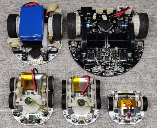
A family of mice v1 (largest) to v5 (smallest)

For context, micromouse is a competition where robots complete to solve mazes of varying pattern but standardized size by driving through them with no guidance or compute offboard of the robot itself. Historically the mazes were 3 meter squares composed of a 16 x 16 grid of cells, each 180mm on a side and 50mm tall, which puts bounds on the size of the robots involved.

What are the hallmarks of a [Keri] micromouse design? Well this is micromouse, so everything is pretty small. But [Keri]’s attention to detail in forming miniaturized mechanisms and 3D structures out of PCBs really stands out. They’ve been building micromouse robots since 2016, testing new design features with each iteration. Versions three and four had a wild suction fan to improve traction for faster maneuvering, but the KERISE v5 removes this to emphasize light weight and small size. The resulting vehicle is a shocking 30mm x 32mm! We’re following along through a translation to English, but we gather that [Keri] feels that there is still plenty of space on the main PCBA now that the fan is gone.

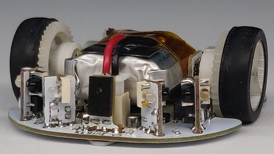
The KERISE v5 front end

The processor is a now familiar ESP32-PICO-D4, though the wireless radios are unused so far. As far as environmental sensing is concerned the v5 has an impressive compliment given its micro size. For position sensing there are custom magnetic encoders and a 3 DOF IMU. And for sensing the maze there are four side-looking IR emitter/receiver pairs and one forward-looking VL6180X laser rangefinder for measurements out to 100 or 150mm. Most of these sensors are mounted on little PCB ‘blades’ which are double sided (check out how the PCB shields the IR emitter from it’s receiver!) and soldered into slots perpendicular to the PCBA that makes up the main chassis. It goes without saying that the rest of the frame is built up of custom 3D printed parts and gearboxes.

If you’d like to build a KERISE yourself, [Keri] has what looks to be complete mechanical, electrical, and firmware sources for v1, v2, and v3 on their Github. To see the KERISE v5 dance on a spinning sheet of paper, check out the video after the break. You don’t want to miss it!

source https://hackaday.com/2020/12/06/these-micro-mice-have-macro-control/