It’s long been common wisdom that one of the safest places to keep your cryptocurrency holdings is in a hardware wallet. These are small, portable devices that encrypt your keys and offer a bit more piece of mind than holding your coins in a soft or web wallet.
But of course, as we know, nothing is totally secure.
It’s worth noting that the hack does require physical access to the wallet — albeit only about fifteen minutes worth. And by “physical access” we mean that the hack leaves the device thoroughly mutilated. The Kraken team started by desoldering the heart of the wallet, a STM32 processor. They then dropped it into a socket on an interface board, and got to glitching.
The hack relies on an attack known as voltage glitching. Essentially, at a precisely-timed moment during the device’s boot sequence, the supply voltage is fluctuated. This enables the chip’s factory bootloader, which can read out the contents of it’s onboard flash memory. The memory is read-protected, but can be accessed 256 bytes at a time through a second voltage glitch. Neither of these attacks work 100% of the time, so if the device fails to boot or the memory remains locked, the FPGA performing the attacks simply tries again. After enough iterations, the Kraken team was able to fully dump the chip’s flash memory.
There’s one more hurdle here — the memory dump is encrypted. Enter brute forcing. Trezor devices allow a maximum pin code length of nine digits, but if you assume the average user’s pin is only four digits then it can be guessed via an automated script in a matter of minutes. Even a longer pin can be worked out in a matter of days or weeks — certainly within the realm of possibility. This yields the seed, which could then be entered into a new hardware wallet to effectively steal any cryptocurrency assets that lived on the original device.
So, aside from some cool hardware hacking techniques, what can we learn from the Kraken Security Lab’s work? First up, for any designers out there, the STM32 is not suitable for high-security applications. For all the end users, this doesn’t mean you need to trash your Trezor (even though this isn’t the first wallet hack we’ve seen). It does mean that you should keep it away from other people, and that you should enable the BIP39 passphrase, which Kraken says can protect against the attack. Perhaps most importantly, this serves to remind us all that nothing is 100% secure.
When it comes to safely riding a bike around cars, the more lights, the better. Ideally, these lights would come on by themselves, so you don’t have to remember to turn them on and off every time. That’s exactly the idea behind [Jeremy Cook]’s latest build — it’s an automatic bike light that detects vibration and lights up some LEDs in response.
The build is pretty simple — a coin cell-powered ATtiny85 reads input from a spring vibration sensor and flashes the LEDs. This is meant to complement [Jeremy]’s primary bike light, which is manually operated and always on. We especially like that form follows function here — the board shape is designed to be zip-tied to the spokes so it’s as close to the action as possible. He cleverly used cardboard and a laser cutter to mock up a prototype for a board that fits between the spokes. Pretty cool for your second professionally-fabbed PCB ever, if you ask us. Ride past the break to check out the build video.
A few weeks ago, a video went viral on social media that depicted a rather unsavory individual receiving what could be described as a “percussive reminder” of social norms courtesy of a bystander armed with a can of Twisted Tea. The video served as inspiration for many a meme, but perhaps none more technically intricate than this air cannon that launches 24 ounces of hard iced tea at better than 100 miles per hour built by [Greg Bejtlich].
It’s all fun and games until somebody brings out the weaponized bead seater.
Technically we’re looking at two different hacks here. The first is the pneumatic launcher put together using a low-cost eBay tire bead seater. These tools are designed to unleash a large volume of air into a tire so it can be properly seated onto the rim, but it doesn’t take much more than a few pieces of PVC pipe from the hardware store to turn it into an impromptu mortar. It’s even got a convenient trigger and a handle to help control the recoil. Though as you can see in the video after the break, it still ends up being a bit too energetic for [Greg] to keep a grip on.
For the projectiles, [Greg] has 3D printed a nose cone and tail fin that snap onto the 24 oz cans in hopes of making them more aerodynamically stable. The slow motion video seems to indicate they aren’t terribly effective, but they certainly look impressive. Spring-loaded control surfaces that deploy after the can leaves the muzzle could be the answer, though at some point you have to ask yourself how far you’re willing to go for an Internet meme.
We have to admit that in the hardware hacking universe, there aren’t generally too many chances to hack elevators. Well, at least not opportunities that don’t also include the risk of incarceration. But fortune favors the bold, and when he found the remains of an elevator control panel in an abandoned Croatian resort hotel, [Davor Cihlar] undertook an extensive and instructive reverse-engineering of the panel.
The video below highlights his efforts, which were considerable given the age and state of the panel. This is a relay-only control panel, after all, with most of the relays missing and a rat’s nest of wires connecting the sockets. So [Davor] put his “RevIng” concept to work. This uses a custom PCB with a microcontroller on-board that plugs into each relay socket and probes the connections between it and every other socket. Very clever stuff, and it presented him with the data needed to develop a ladder-logic diagram of the board, with the help of some custom software.
With the original logic in hand, [Davor] set about building a simulator for the panel. It’s a lovely piece of work, with buttons and lights to mimic the control panel inside the elevator car, as well as the call stations that would have graced each lobby of the hotel. Interestingly, he found logic that prevented the elevator from being called to some floors from anywhere but inside the car. The reason remains a mystery, but we suppose that a hotel built by Penthouse publisher [Bob Guccione] would have plenty of secrets.
We love the supremely satisfying clickiness of this build, and the reverse engineering prowess on display, but we can’t find much practical use for something like this. Then again, DIY elevators are a thing.
In 2018, when KiCad Version 5 modernized the venerable 4.X series, it helped push KiCad to become the stable and productive member of the open source EDA landscape that we know today. It has supported users through board designs both simple and complex, and like a tool whose handle is worn into a perfect grip, it has become familiar and comfortable. For those KiCad users that don’t live on the bleeding edge with nightly builds it may not be obvious that the time of version 6 is nearly upon us, but as we start 2021 it rapidly approaches. Earlier this month [Peter Dalmaris] published a preview of the changes coming version 6 and we have to admit, this is shaping up to be a very substantial release.
Don’t be mistaken, this blog post may be a preview of new KiCad features but the post itself is extensive in its coverage. We haven’t spent time playing with this release yet so we can’t vouch for completeness, but with a printed length of nearly 100 pages it’s hard to imagine [Peter] left anything out! We skimmed through the post to extract a few choice morsels for reproduction here, but obviously take a look at the source if you’re as excited as we are.
There’s No Place Like (0, 0)
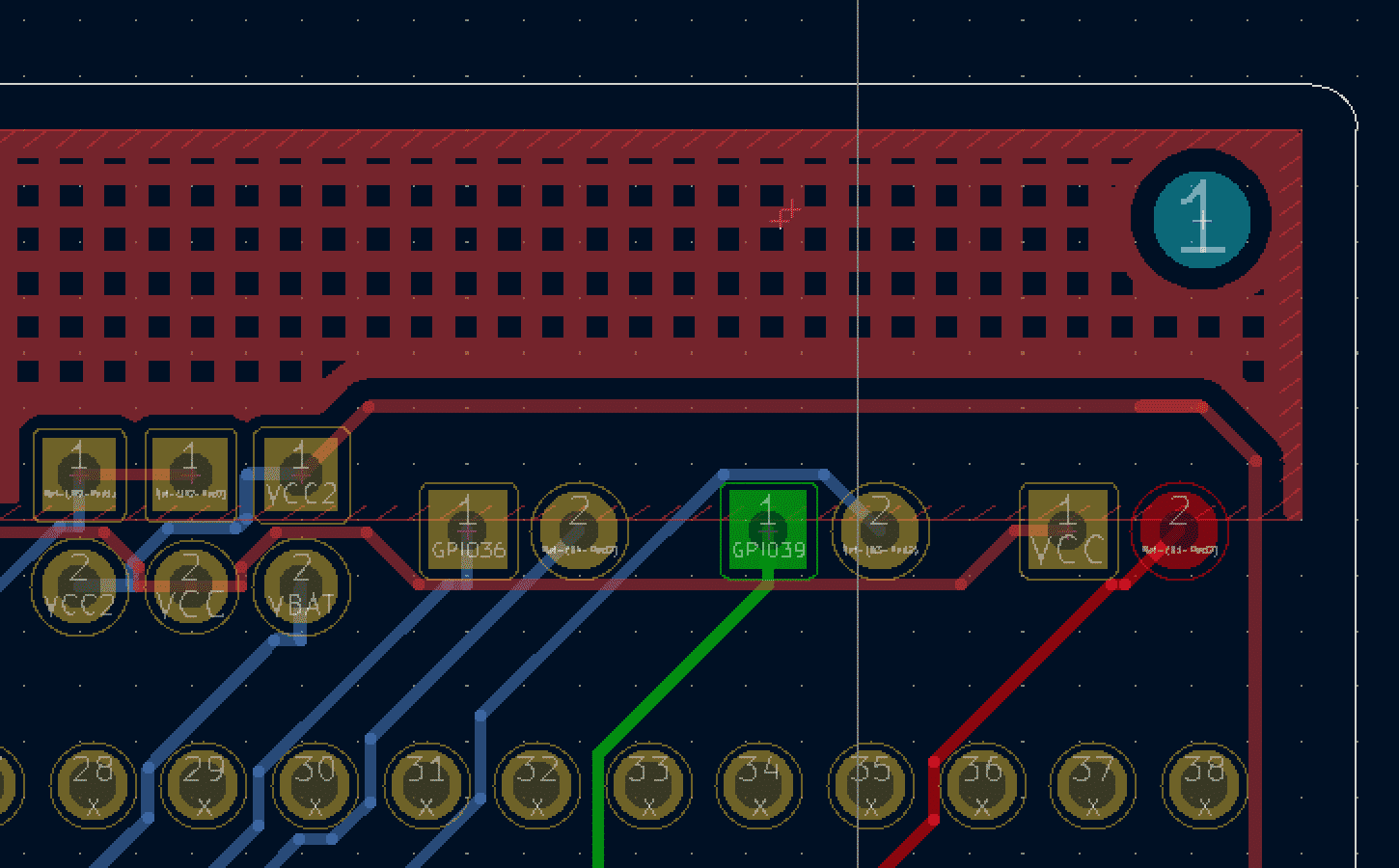
The mythical hatched fill
Starting with the foundation, KiCad 6 will finally bring a configurable coordinate system! We’ve found that a significant stumbling block for new users is that the default KiCad coordinates start at the upper left instead of the lower left, as in most CAD and drawing tools.
Version 6 will allow the user to relocate the origin as well as flip either axis, allowing for maximum ordinal freedom. Clearly it doesn’t take much to get us excited, does it?
Rounding Traces and Filling Zones, Mostly
Another historically missing feature in KiCad is curved traces. V6 moves part of the way there, allowing traces to have rounded fillets. This doesn’t quite get to the groovy curvy traces of the 70s but it’s progress in the right direction.
Along similar lines there is new variety in the way a zone can be filled. Now instead of being forced into a solid fill there is a second choice; hatched fill! We say the more the merrier! Next stop; hearts, stars and horseshoes?
Getting Together with Groups
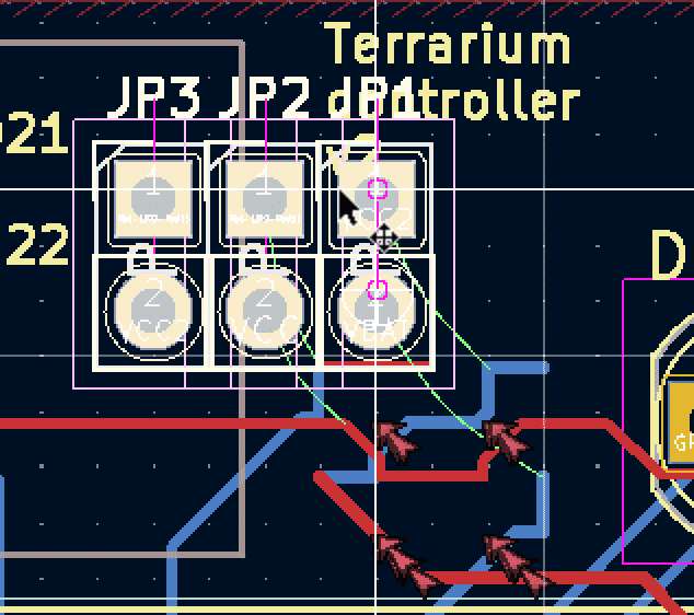
A flock of grouped components in layout
It may seem minor, but should be appreciated by anyone who has worked with carefully arranged groups of components during layout; items can be grouped! It’s always been possible to select multiple elements and drag them together, but that grouping was lost as soon as the selection changed. In KiCad 6 components can be explicitly grouped, allowing you to move those pesky headers around all at once, in perpetuity.
Bussing in the Signals
Even after using version 5 for years, signal busses in KiCad schematics seemed like an ugly duckling with a usage so awkward that they weren’t worth using. [Peter]’s overview has taught us a few new things about that older tool that we didn’t know under the rubric “enhanced bus handling”. For instance, the older version 5 allows the user to textually specify net names to connect across a bus instead of forcing the use of bus entry connections and individual net labels.
Version 6 makes busses significantly more powerful. It’s now possible to specify more elaborate and less uniform net names that share a single bus, and there are graphical hooks in context menus that allow you to “unfold” individual nets from the bus without the guesswork required in version 5. And as an added bonus, in version 6 the visual style of busses can be changed. We’re excited to start getting our signals together!
That’s Not All Folks
Whew, what a list! And that was but a tiny fraction of the improvements in KiCad 6, or the coverage from [Peter]’s excellent post.
It’s worth noting that the post is based on nightly builds euphemistically versioned 5.99. Until the release is officially cut, features and functionality are subject to change, but everything is publicly available to try out in the nightly builds if something catches your eye.
Considering the state of well, everything, we can’t tell you how glad we are to be out of school. That goes double for not being a teacher these days. [Elena] had some awesome light-up tactile buttons set aside for a killer Kerbal Space Program controller, but it’s funny how a pandemic will change your priorities. Instead, those buttons found a good home in this colorful and enticing Zoom control panel.
[Elena]’s ready pile of Arduinos yielded no Leonardos or Pro Micros, but that’s okay because there’s a handy bootloader out there that allows you to reprogram the USB interface chip of an Uno or a Mega and use it as a keyboard. After setting that up, it was mostly a matter of wiring all those latching and momentary buttons and LEDs to the Mega and making them look fantastic with a set of icons. (We all know the big red mushroom button is for aborting the call; so does it really need an icon?)
By now we’re all used to the requirements imposed by the pandemic, of social distancing and wearing masks indoors. But as [polyfloyd] and the rest of the board at Bitlair hackerspace in Amersfoort in the Netherlands were concerned, there are still risk factors to consider when inside a building. Without fresh air the concentration of virus-bearing droplets can increase, and the best way they could think of to monitor this was to install a set of CO2 sensors. To run them they didn’t need to buy any new hardware, instead they turned to a set of event badges, from 2017s SHA hacker camp.
This badge sported an ESP32 module with an e-ink screen, and of most interest for this project it still has a supported software platform and comes with a handy expansion connector on the rear. The commonly-available MH-Z19 infra-red CO2 sensor and BME280 humidity sensor fit on a PCB that follows the shape of the badge with a protrusion at the top on which they appear as an integrated unit. Processing those readings is a MicroPython badge app that issues warnings via MQTT and plots a CO2 graph on the screen. Everything is available, both the hardware in a GitHub repository and the software as a badge.team app.
We applaud anyone who makes use of an event badge for a project, and especially so for using one years after the event. The SHA badge and its descendants are uniquely suited to this through their well-supported platform, so if you have one in a drawer we’d urge you to pull it out and give it a try.
By and large, alarm clocks (including phones that double as alarm clocks) are annoyingly alarming. If it’s not the light or the sound, it’s both. Yes, we know that’s the point of an alarm clock, but sometimes life presents opportunities to check the time and/or the weather and sleep in a little bit longer based on the result. We don’t know about you, but loud noises and eye-blasting light are not conducive to getting back to sleep, especially if you’re a light sleeper.
In [Stavros Korokithakis]’ case, if it’s a tennis practice morning but it’s raining, then it’s no longer a tennis practice morning and he can go back to sleep for a while. A phone seems perfect for this, but the problem is that it provides too much information: the phone can’t check the weather without the internet, and once it has internet access, a bunch of eye-opening notifications come flooding in.
[Stavros] had a long list of must-haves when it came to building the ultimate alarm clock, and we can totally get behind that. He needed something smarter than the average off-the-shelf clock radio, but nothing too smart. Enter the ESP8266. As long as it has an internet connection, it can fetch the time and the weather, which is really all that [Stavros] needs. It gets the current temperature, wind speed, and forecast for the next two hours with the OpenWeather API, and this information is converted to icons that are easy to read at a sleepy, one-eyed glance at the OLED.
Adaptive brightness was high on the list of must-haves, which [Stavros] solved by adding a photoresistor to judge the ambient light and adjust the OLED screen brightness appropriately. And he really did think of everything — the octagonal shape allows for the perfect angle for reading from bed. There’s just one problem — it can’t accept input, so it doesn’t actually function as an alarm clock. But it makes a damn good bedside clock if you ask us.
To get its engineers thinking about design for assembly back in the 1980s, Westinghouse made a video about a product optimized for assembly: the IBM Proprinter. The technology may be dated, but the film presents a great look at how companies designed not only for manufacturing, but also for ease of assembly.
It’s not clear whether Westinghouse and IBM collaborated on the project, but given the inside knowledge of the dot-matrix printer’s assembly, it seems like they did. The first few minutes are occupied by an unidentified Westinghouse executive talking about design for assembly in general terms, and how it impacts the bottom line. Skip ahead to 3:41 if talking suits aren’t your thing.
Once the engineer gets going on the printer, though, things get really interesting. The printer’s guts are laid out before him, ready to be assembled. What’s notably absent from the table are tools — the Proprinter was so well designed that the only tool needed is a pair of human hands. And they don’t have to be particularly dexterous hands, either — the design favors motions that are straight down, letting gravity assist the assembly process and preventing assemblers from the need to contort their bodies. Almost everything is held in place by compliant mechanisms built into the plastic parts. There are a few gems in the film, like the plastic lead screw that drives the printhead, obviating the need to string a fussy timing belt, or the unique roller that twists to lock onto a long shaft, rather than having to be pushed to its center.
We found this film which we’ve placed below the break to be very instructive, and the fact that a device as complex as a printer can be assembled in just a few minutes without picking up a single tool is pretty illustrative of the power of designing for assembly. Slick designs that can’t be manufactured at scale are all too common in this age of powerful design tools and desktop manufacturing, so these lessons from the past might be worth relearning.
We’ve all seen those tiny little RC cars that can climb walls thanks to the suction generated with fans. Their principle is essentially the opposite to that of a hovercraft. [Engineering After Hours] wanted to build his own RC car that could do the same, driving upside down and generating huge amounts of grip.
The build is based on a Traxxas RC car, but heavily modified for the task. An undertray is crafted, with ducts feeding a pair of twin 50mm electric fans. A skirt is fitted around the edge of the undertray, helping create a seal to maximise the downforce generated. This skirt is the area of much engineering effort, as it must form a good seal with the ground, particularly over minor pertubations, without creating undue levels of friction. Suspension components correspondingly need to be beefed up to stop the car bottoming out with the huge downforce generated by the fan system.
After much experimentation, the kinks are worked out, and the car is able to drive upside down successfully. It generates far more downforce than earlier wing experiments from [Engineering After Hours], as expected – with a tradeoff of higher weight and complexity. With the plan to create an RC car capable of huge lateral acceleration, we can’t wait to see what comes next. Video after the break.
A reality of flying RC aircraft is that at some point, one of your birds is going to fall in the line of duty. It could get lost in the clouds never to be seen again, or perhaps it will become suddenly reacquainted with terra firma. Whatever the reason, your overall enjoyment of the hobby depends greatly on how well you can adapt to the occasional loss.
Based on what we’ve seen so far, we’d say [Rural Flyer] has the right temperament for the job. After losing one of his quadcopters in an unfortunate FPV incident, he decided to repurpose the proprietary gimbal it left behind. If he still had the drone he could have slipped a logic analyzer in between its connection with the motorized camera to sniff out the communication protocol, but since that was no longer an option, he had to get a little creative.
Figuring out the power side of things was easy enough thanks to the silkscreen on the camera’s board, and a common 5 V battery eliminator circuit (BEC) connected to the drone’s 7.4 V battery pack got it online. A cobbled together adapter allowed him to mount it to one of his other quads, but unfortunately the angle wasn’t quite right.
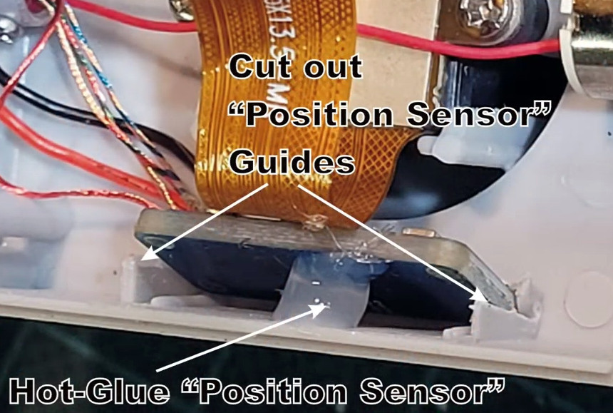
[Rural Flyer] wanted the camera tilted down about 15 degrees, but since he didn’t know how to talk to it, he employed a clever brute force solution. After identifying the accelerometer board responsible for determining the camera’s position, he use a glob of hot glue to push the sensor off of the horizontal. Providing this physical offset to the sensor data caused the camera to automatically move itself to exactly where he wanted it.
In the video after the break, you can see the hacked up gimbal seems to perform admirably when attached to its new mothership. Using the original drone’s smartphone application, [Rural Flyer] is able to view the live stream and record the action. Thanks to the new antenna he whipped up for the transmitter, it sounds like he’s even improved things compared to the stock hardware.
Have a rusty collection of protoboards wired together that would benefit from mechanical support? Working on putting together a robot and need to attach PCBAs without drilling holes, zipping a cable tie, or globing hot glue? Add some stud holes with [James Munns]’ Brick Mount! This isn’t the first time we’ve seen an interface between everyone’s favorite Nordic building system and circuitboards, but this implementation has the elegance we’ve come to expect from [James]’ software work.
4×8 Feather Medium protoboard
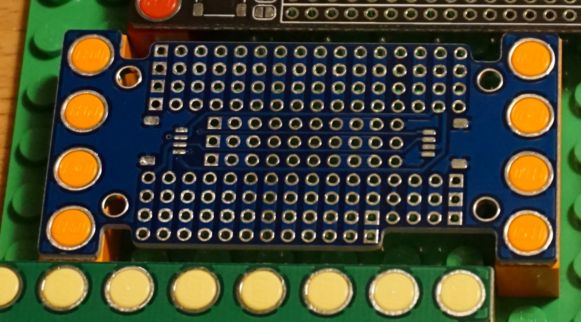
The project repository contains two things: a KiCad library with components for holes in standard patterns and sizes (1×1, 1×2, etc) and a series of protoboards made with those hole components. The protoboards feature a couple common elements; QUIIC connectors for easy chaining between them and holes in the middle or edges for easy mounting on studs. Some are intended to be carriers for Feather-format PCBAs (very convenient!) and others are primarily undifferentiated prototyping space. Of particular note is the “medium” Feather breakout seen to the left, which incorporates clever cutouts to make it easy to wires down under the board so it can be mounted flush against another board.
The thesis here is that getting custom PCBs fabricated is easier and less expensive than ever before. So easy and inexpensive that fabricating customized protoboard to use in one-off projects is cost-efficient enough to be worthwhile. Waste concerns aside this does seem like a great way to level up those temporary projects which find a more permanent home.
PCI Express (PCIe) has been around since 2003, and in that time it has managed to become the primary data interconnect for not only expansion cards, but also high-speed external devices. What also makes PCIe interesting is that it replaces the widespread use of parallel buses with serial links. Instead of having a bus with a common medium (traces) to which multiple devices connect, PCIe uses a root complex that directly connects to PCIe end points.
This is similar to how Ethernet originally used a bus configuration, with a common backbone (coax cable), but modern Ethernet (starting in the 90s) moved to a point-to-point configuration, assisted by switches to allow for dynamic switching between which points (devices) are connected. PCIe also offers the ability to add switches which allows more than one PCIe end point (a device or part of a device) to share a PCIe link (called a ‘lane’).
This change from a parallel bus to serial links simplifies the topology a lot compared to ISA or PCI where communication time had to be shared with other PCI devices on the bus and only half-duplex operation was possible. The ability to bundle multiple lanes to provide less or more bandwidth to specific ports or devices has meant that there was no need for a specialized graphics card slot, using e.g. an x16 PCIe slot with 16 lanes. It does however mean we’re using serial links that run at many GHz and must be implmented as differential pairs to protect signal integrity.
This all may seem a bit beyond the means of the average hobbyist, but there are still ways to have fun with PCIe hacking even if they do not involve breadboarding 7400-logic chips and debugging with a 100 MHz budget oscilloscope, like with ISA buses.
High Clocks Demand Differential Pairs
PCIe version 1.0 increases the maximum transfer rate when compared to 32-bit PCI from 133 MB/s to 250 MB/s. This is roughly the same as a PCI-X 64-bit connection (at 133 MHz) if four lanes are used (~1,064 MB/s). Here the PCIe lanes are clocked at 2.5 GHz, with differential signaling send/receive pairs within each lane for full-duplex operation.
Today, PCIe 4 is slowly becoming adopted as more and more systems are upgraded. This version of the standard runs at 16 GHz, and the already released PCIe version 5 is clocked at 32 GHz. Although this means a lot of bandwidth (>31 GB/s for an x16 PCIe 4 link), it comes with the cost of generating these rapid transitions, keeping these data links full, and keeping the data intact for more than a few millimeters. That requires a few interesting technologies, primarily differential signaling and SerDes.
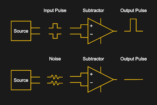
Basic visualization of how differential signaling works.
Differential signaling is commonly used in many communication protocols, including RS-422, IEA-485, Ethernet (via twisted-pair wiring), DisplayPort, HDMI and USB, as well as on PCBs, where the connection between the Ethernet PHY and magnetics is implemented as differential pairs. Each side of the pair conducts the same signal, just with one side having the inverted signal. Both sides have the same impedance, and are affected similarly by (electromagnetic) noise in the environment. As a result, when the receiver flips the inverted signal back and merges the two signals, noise in the signal will become inverted on one side (negative amplitude) and thus cancel out the noise on the non-inverted side.
The move towards lower signal voltages (in the form of LVDS) in these protocols and the increasing clock speeds makes the use of differential pairs essential. Fortunately they are not extremely hard to implement on, say, a custom PCB design. The hard work of ensuring that the traces in a differential pair have the same length is made easier by common EDA tools (including KiCad, Autodesk Eagle, and Altium) thatl provide functionality for making the routing of differential pairs a semi-automated affair.
Having It Both Ways: SerDes
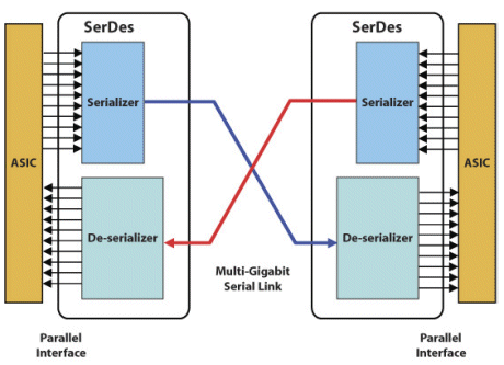
Schematic diagram of a SerDes link.
A Serializer/Deserializer (SerDes) is a functional block that is used to convert between serial data and parallel interfaces. Inside an FPGA or communications ASIC the data is usually transferred on a parallel interface, with the parallel data being passed into the SerDes block, where it is serialized for transmission or vice-versa. The PCIe PMA (physical media attachment) layer is the part of the protocol’s physical layer where SerDes in PCIe is located. The exact SerDes implementation differs per ASIC vendor, but their basic functionality is generally the same.
When it comes to producing your own PCIe hardware, an easy way to get started is to use an FPGA with SerDes blocks. One still needs to load the FPGA with a design that includes the actual PCIe data link and transaction layers, but these are often available for free, such as with Xilinx FPGAs.
PCIe HDL Cores
Recent Xilinx FPGAs not only integrate SerDes and PCIe end-point features, but Xilinx also provides free-as-in-beer PCIe IP blocks (limited to x8 at PCIe v2.1) for use with these hardware features that (based on the license) can be used commercially. If one wishes for a slightly less proprietary solution, there are Open Source PCIe cores available as well, such as this PCIe Mini project that was tested on a Spartan 6 FPGA on real hardware and provides a PCIe-to-Wishbone bridge, along with its successor project, which targets Kintex Ultrascale+ FPGAs.
On the other sides of the fence, the Intel (formerly Altera) IP page seems to strongly hint at giving their salesperson a call for a personalized quote. Similarly, Lattice has their sales people standing by to take your call for their amazing PCIe IP blocks. Here one can definitely see the issue with a protocol like PCIe: unlike ISA or PCI devices which could be cobbled together with a handful of 74xx logic chips and the occasional microcontroller or CPLD, PCIe requires fairly specialized hardware.
Even if one buys the physical hardware (e.g. FPGA), use of the SerDes hardware blocks with PCIe functionality may still require a purchase or continuous license (e.g. for the toolchain) depending on the chosen solution. At the moment it seems that Xilinx FPGAs are the ‘go-to’ solution here, but this may change in the future.
Also of note here is that the PCIe protocol itself is officially available to members of PCI-SIG. This complicates an already massive undertaking if one wanted to implement the gargantuan PCIe specification from scratch, and makes it even more admirable that there are Open Source HDL cores at all for PCIe.
Putting it Together
PCI Express x1 edge connector drawing with pin numbers.
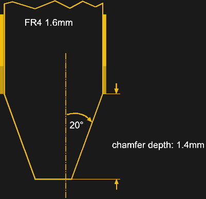
The basic board design for a PCIe PCB is highly reminiscent of that of PCI cards. Both use an edge connector with a similar layout. PCIe edge connectors are 1.6 mm thick, use a 1.0 mm pitch (compared to 1.27 mm for PCI), a 1.4 mm spacing between the contact fingers and the same 20° chamfer angle as PCI edge connectors. A connector has at least 36 pins, but can have 164 pins in an x16 slot configuration.
PCIe card edge connector cross section.
An important distinction with PCIe is that there is no fixed length of the edge connector, as with ISA, PCI and similar interfaces. Those have a length that’s defined by the width of the bus. In the case of PCIe, there is no bus, so instead we get the ‘core’ connector pin-out with a single lane (x1 connector). To this single lane additional ‘blocks’ can be added, each adding another lane that gets bonded so that the bandwidth of all connected lanes can be used by a single device.
In addition to regular PCIe cards, one can also pick from a range of different PCIe devices, such as Mini-PCIe. Whatever form factor one chooses, the basic circuitry does not change.
This raises the interesting question of what kind of speeds your PCIe device will require. On one hand more bandwidth is nice, on the other hand it also requires more SerDes channels, and not all PCIe slots allow for every card to be installed. While any card of any configuration (x1, x4, x8 or x16) will fit and work in an x16 slot (mechanical), smaller slots may not physically allow a larger card to fit. Some connectors have an ‘open-ended’ configuration, where you can fit for example an x16 card into an x1 slot if so inclined. Other connectors can be ‘modded’ to allow such larger cards to fit unless warranty is a concern.
The flexibility of PCIe means that the bandwidth scales along with the number of bonded lanes as well as the PCIe protocol version. This allows for graceful degradation, where if, say, a PCIe 3.0 card is inserted into a slot that is capable of only PCIe 1.0, the card will still be recognized and work. The available bandwidth will be severely reduced, which may be an issue for the card in question. The same is true with available PCIe lanes, bringing to mind the story of cryptocoin miners who split up x16 PCIe slots into 16 x1 slots, so that they could run an equal number of GPUs or specialized cryptocoin mining cards.
It’s Full of PCIe
This flexibility of PCIe has also led to PCIe lanes being routed out to strange and wonderful new places. Specifications like Intel’s Thunderbolt (now USB 4) include room for multiple lanes of PCIe 3.0, which enables fast external storage solutions as well as external video cards that work as well as internal ones.
Solid-state storage has moved over from the SATA protocol to NVMe, which essentially defines a storage device that is directly attached to the PCIe controller. This change has allowed NVMe storage devices to be installed or even directly integrated on the main logic board.
Clearly PCIe is the thing to look out for these days. We have even seen that System-on-Chips (SoCs), such as those found on Raspberry Pi 4 boards now come with a single PCIe lane that has already been hacked to expand those boards in ways thought inconceivable. As PCIe becomes more pervasive, this seems like a good time to become more acquainted with it.
The video that you can find below the break is a long and detailed one, but in that detail lies touches that set the conversion apart from the norm. We’re treated to a full-run-down of USB-PD module design and chip programming, and then the mechanics of the 1-wire chip through which the Dell ties itself in with only Dell power supplies. Programming this chip in particular is something of a challenge.
It’s the mechanical design that sets this one apart. He started with an odd-shaped space that had contained the barrel jack socket and a ferrite choke, and designed a PCB to fit it exactly. 3D-printing a model to check for fit is attention to detail at the stratospheric level. The result is a fit that looks almost as though it was part of the original manufacture, and which should keep the laptop useful for years to come.
Surface mount devices were once upon a time considered a huge imposition for the electronics hobbyist. Tiny, difficult to solder by hand, and barely even labelled, many wondered whether the pastime was about to hit a brick wall entirely. Instead, enterprising hackers and makers set about learning new tricks and techniques to work with the technology, and we’ve never looked back since. [Seon] is one such enthusiast, and has built a useful turntable for making manually picking and placing boards easier. (Video, embedded below.)
The design is something [Seon] has refined gradually over time, having built two initial versions of the turntable before finally feeling ready to do a wider public release with version 3. It consists of a rotating caddy that has radial slots that hold all the tiny SMD parts, that can be labelled for easy parts identification. There’s also an acrylic window that ensures only one segment of the caddy is open at a time, to avoid accidentally dropping similar, tiny looking parts into adjacent slots – a big improvement over the first design. There’s then a smaller rotating central pad upon which a PCB can be placed, ready to receive parts.
The original Hasbro “Think-a-Tron”, a toy from the dawn of the computer revolution, was billed with the slogan, “It thinks! It answers! It remembers!” It, of course, did only one of these things, but that didn’t stop the marketers of the day from crushing the hopes and dreams of budding computer scientists and their eager parents just to make a few bucks. It’s not like we’re bitter or anything — just saying.
In an effort to right past wrongs, [Michael Gardi] rebuilt the 1960s “thinking machine” toy with modern components. The original may not have lived up to the hype, but at least did a decent job of evoking the room-filling computers of the day is a plastic cabinet with a dot-matrix-like display. The toy uses “punch-cards” with printed trivia questions that are inserted into the machine to be answered. A disk with punched holes spins between a light bulb and the display lenses, while a clever linkage mechanism reads the position of a notch in the edge of the card and stops the wheel to display the letter of the correct answer.
[Michael]’s update to the Think-aTron incorporates what would have qualified as extraterrestrial technology had it appeared in the 1960s. A 35-LED matrix with a 3D-printed diffuser and case form the display, with trivia questions and their answer as a QR code standing in for the punch-cards.He also added a pair of user consoles, so players can lock-in and answer before an ESP32-Cam reads the QR code and displays the answer on the LED matrix, after playing some suitable “thinking music” through a speaker.
As usual with [Michael]’s retrocomputing recreations, the level of detail here is fantastic. We especially like the custom buttons; controls like these seem to be one of his specialties judging by his slide switches and his motorized rotary switch.
The Raspberry Pi Pico came out of absolutely nowhere, and has taken the maker world by storm. At the low, low cost of $4, packing some seriously grunty original silicon, and even available free on the cover of magazines, it’s already got a legion of fans. As with any new popular platform, there’s a scramble to get everything under the sun running on the hardware. Already, ArduCAM is up and running on the Raspberry Pi Pico!
Based on the OV2640 image sensor, the ArduCAM is useful for microcontroller applications thanks to its onboard JPEG encoder. This limits the amount of RAM needed onboard the microcontroller to deal with the images fed from the camera. With the Pico now on the market, the team behind ArduCAM set about writing a library to get everything playing nicely with the SPI camera. It’s available on Github, complete with an example program so you can check everything is functional right out of the box. The easiest way to get up and running is from a Raspberry Pi environment, but the Pico acts as a USB Mass Storage device so can be programmed from virtually anywhere.
For this project, [Dan] wanted to make sure no original functionality was lost. The radio still functions on the AM/FM bands, but now with the flip of a switch, he can listen to the audio coming his way courtesy of a Apt-X low-latency Bluetooth receiver. It sounds like the link is quick enough that he can even use this as a wireless speaker for watching TV, which isn’t always possible with cheaper chipsets that introduce a noticeable lag.
Isolating the audio trace.
The trick was to track down the receiver IC, a Silicon Labs chip similar to ones we’ve seen used in a few DIY radio projects previously. A peek at the datasheet told him which pins were carrying the audio signal, and after following them around the board, he found a convenient spot to cut the trace before it went into the volume control. From there is was just a matter of wiring in a SPDT slide switch that allowed him to select which device was passed through to the radio’s audio hardware.
While he had everything apart, [Dan] exorcised the Apt-X’s original 300 mAh LiPo pouch and replaced it with a DC-DC converter connected to the radio’s battery compartment. This allows him to run all of the hardware off of the same set of rechargeable NiMH cells, and also provides considerably improved runtime for the Bluetooth receiver.
Now as for physically integrating the Apt-X into the case of the radio…well, what can we say? [Dan] admits it’s a bit rough, but then the point was never to enter the thing into beauty pageants. It works well enough for his purposes, and in the end that’s all that matters.
For this project, [Dan] wanted to make sure no original functionality was lost. The radio still functions on the AM/FM bands, but now with the flip of a switch, he can listen to the audio coming his way courtesy of a Apt-X low-latency Bluetooth receiver. It sounds like the link is quick enough that he can even use this as a wireless speaker for watching TV, which isn’t always possible with cheaper chipsets that introduce a noticeable lag.
Isolating the audio trace.
The trick was to track down the receiver IC, a Silicon Labs chip similar to ones we’ve seen used in a few DIY radio projects previously. A peek at the datasheet told him which pins were carrying the audio signal, and after following them around the board, he found a convenient spot to cut the trace before it went into the volume control. From there is was just a matter of wiring in a SPDT slide switch that allowed him to select which device was passed through to the radio’s audio hardware.
While he had everything apart, [Dan] exorcised the Apt-X’s original 300 mAh LiPo pouch and replaced it with a DC-DC converter connected to the radio’s battery compartment. This allows him to run all of the hardware off of the same set of rechargeable NiMH cells, and also provides considerably improved runtime for the Bluetooth receiver.
Now as for physically integrating the Apt-X into the case of the radio…well, what can we say? [Dan] admits it’s a bit rough, but then the point was never to enter the thing into beauty pageants. It works well enough for his purposes, and in the end that’s all that matters.
The rig uses a 60W ultrasonic transducer, operating at approximately 40 KHz, to generate a standing wave in combination with a reflector – essentially a rigid piece of material off which sound waves can be bounced. The interaction between the sound waves as they are emitted from the transducer and bounce off the reflector creates what is known as a standing wave, wherein there are areas of high and low amplitude that do not move in space. These areas correspond to the wavelength of the emission from the transducer, and allow lightweight pieces of styrofoam to be placed in to the low amplitude areas, where they are held in place by the wave.
Since we’ve started inviting them into our homes, many of us have began casting a wary eye at our smart speakers. What exactly are they doing with the constant stream of audio we generate, some of it coming from the most intimate and private of moments? Sure, the big companies behind these devices claim they’re being good, but do any of us actually buy that?
It seems like the most prudent path is to not have one of these devices, but they are pretty useful tools. So this hardware mute switch for an Amazon Echo represents a middle ground between digital Luddism and ignoring the possible privacy risks of smart speakers. Yes, these devices all have software options for disabling their microphone arrays, but as [Andrew Peters] relates it, his concern is mainly to thwart exotic attacks on smart speakers, some of which, like laser-induced photoacoustic attacks, we’ve previously discussed. And for that job, only a hardware-level disconnect of the microphones will do.
To achieve this, [Andrew] embedded a Seeeduino Xiao inside his Echo Dot Gen 2. The tiny microcontroller grounds the common I²S data line shared by the seven (!) microphones in the smart speaker, effective disabling them. Enabling and disabling the mics is done via the existing Dot keys, with feedback provided by tones sent through the Dot speaker. It’s a really slick mod, and the amount of documentation [Andrew] did while researching this is impressive. The video below and the accompanying GitHub repo should prove invaluable to other smart speaker hackers.
Since we’ve started inviting them into our homes, many of us have began casting a wary eye at our smart speakers. What exactly are they doing with the constant stream of audio we generate, some of it coming from the most intimate and private of moments? Sure, the big companies behind these devices claim they’re being good, but do any of us actually buy that?
It seems like the most prudent path is to not have one of these devices, but they are pretty useful tools. So this hardware mute switch for an Amazon Echo represents a middle ground between digital Luddism and ignoring the possible privacy risks of smart speakers. Yes, these devices all have software options for disabling their microphone arrays, but as [Andrew Peters] relates it, his concern is mainly to thwart exotic attacks on smart speakers, some of which, like laser-induced photoacoustic attacks, we’ve previously discussed. And for that job, only a hardware-level disconnect of the microphones will do.
To achieve this, [Andrew] embedded a Seeeduino Xiao inside his Echo Dot Gen 2. The tiny microcontroller grounds the common I²S data line shared by the seven (!) microphones in the smart speaker, effective disabling them. Enabling and disabling the mics is done via the existing Dot keys, with feedback provided by tones sent through the Dot speaker. It’s a really slick mod, and the amount of documentation [Andrew] did while researching this is impressive. The video below and the accompanying GitHub repo should prove invaluable to other smart speaker hackers.
We’ve all likely seen the amazing images possible with a scanning electron microscope. An SEM can yield remarkably detailed 3D images of the tiniest structures, and they can be invaluable tools for research. But blasting high-energy cathode rays onto metal-coated samples in the vacuum chamber of a bulky and expensive instrument isn’t the only way to make useful images, as this home-brew laser scanning microscope demonstrates.
This one comes to us by way of [GaudiLabs], a Swiss outfit devoted to open-source lab equipment that enables citizen science; we saw their pocket-sized thermal cycler for PCR a while back. The basic scheme here is known as confocal laser scanning fluorescence microscopy, where a laser at one wavelength excites fluorescent tags bound to structures in a sample. Light emitted by the tags is collected, and a 3D image is built up from multiple scans of the sample at different focal planes.
Like many DIY projects, this microscope is built from old DVD parts, specifically the pickup heads. The precision optics in these commonly available assemblies, which are good enough to read pits as small as 150 nm on a Blu-Ray DVD, are well-suited for resolving similarly sized microstructures. One DVD pickup is used to scan the laser in the X-axis, while the other head is modified to carry the sample and move it in the Y-axis. The pickup head coils and laser are driven by an Arduino carried on a custom PCB along with the DVD heads. Complete build files are posted on GitHub for anyone interested in recreating this work.
We love tips like this that dig back a bit and find things we missed the first go-around. And the equipment [GaudiLabs] lists really has potential for the budding biohacker, which we also like.
The BMW i3 debuted on the market in late 2013, one of the brand’s first electric cars. Also available with an optional range-extending engine, early models featured a 60 Ah battery providing up to 130km range on a full charge. However, times have changed, and over the years, BMW have updated the model with larger capacity batteries over the years. So what does it take to retrofit an older model with the newer, fatter, juicer 120 Ah pack?
It’s all helpfully laid out in a video by [Daniel], who notes that it’s not a job for the faint of heart or poorly equipped. The good news is that, mechanically, the newer batteries have the same external dimensions as the older packs, meaning they can be bolted in without requiring any cutting, welding or, adapters. But that’s about it for the good news. The batteries are cooled by the air conditioning system, meaning that removal and replacement means draining the system of refrigerant using highly expensive specialised hardware. Additionally, many batteries in crashed cars are disabled when the airbags are triggered for safety reasons, requiring unlocking through BMW’s proprietary software or replacement of the internal battery controller. Then there’s the usual laundry list of gradual changes that happen across any automotive line, meaning that certain model years and trim packages can have incompatible plugs and connectors or other features.
Overall, it can be quite a bit of work to do, and with the tools required, something that needs the services of a dedicated mechanic’s workshop. However, find an experienced shop that regularly works with EVs, and you might find they can facilitate the upgrade for you without too much fuss. We’ve seen [Daniel] tackle upgrades before, such as a much easier swap on the Nissan Leaf. Video after the break.
The BMW i3 debuted on the market in late 2013, one of the brand’s first electric cars. Also available with an optional range-extending engine, early models featured a 60 Ah battery providing up to 130km range on a full charge. However, times have changed, and over the years, BMW have updated the model with larger capacity batteries over the years. So what does it take to retrofit an older model with the newer, fatter, juicer 120 Ah pack?
It’s all helpfully laid out in a video by [Daniel], who notes that it’s not a job for the faint of heart or poorly equipped. The good news is that, mechanically, the newer batteries have the same external dimensions as the older packs, meaning they can be bolted in without requiring any cutting, welding or, adapters. But that’s about it for the good news. The batteries are cooled by the air conditioning system, meaning that removal and replacement means draining the system of refrigerant using highly expensive specialised hardware. Additionally, many batteries in crashed cars are disabled when the airbags are triggered for safety reasons, requiring unlocking through BMW’s proprietary software or replacement of the internal battery controller. Then there’s the usual laundry list of gradual changes that happen across any automotive line, meaning that certain model years and trim packages can have incompatible plugs and connectors or other features.
Overall, it can be quite a bit of work to do, and with the tools required, something that needs the services of a dedicated mechanic’s workshop. However, find an experienced shop that regularly works with EVs, and you might find they can facilitate the upgrade for you without too much fuss. We’ve seen [Daniel] tackle upgrades before, such as a much easier swap on the Nissan Leaf. Video after the break.