When do you need to use a real-time operating system (RTOS) for an embedded project? What does it bring to the table, and what are the costs? Fortunately there are strict technical definitions, which can also help one figure out whether an RTOS is the right choice for a project.
The “real-time” part of the name namely covers the basic premise of an RTOS: the guarantee that certain types of operations will complete within a predefined, deterministic time span. Within “real time” we find distinct categories: hard, firm, and soft real-time, with increasingly less severe penalties for missing the deadline. As an example of a hard real-time scenario, imagine a system where the embedded controller has to respond to incoming sensor data within a specific timespan. If the consequence of missing such a deadline will break downstream components of the system, figuratively or literally, the deadline is hard.
In comparison soft real-time would be the kind of operation where it would be great if the controller responded within this timespan, but if it takes a bit longer, it would be totally fine, too. Some operating systems are capable of hard real-time, whereas others are not. This is mostly a factor of their fundamental design, especially the scheduler.
In this article we’ll take a look at a variety of operating systems, to see where they fit into these definitions, and when you’d want to use them in a project.
A Matter of Scale
Different embedded OSes address different types of systems, and have different feature sets. The most minimalistic of popular RTOSes is probably FreeRTOS, which provides a scheduler and with it multi-threading primitives including threads, mutexes, semaphores, and thread-safe heap allocation methods. Depending on the project’s needs, you can pick from a number of dynamic allocation methods, as well as only allow static allocation.
On the other end of the scale we find RTOSes such as VxWorks, QNX and Linux with real-time scheduler patches applied. These are generally POSIX-certified or compatible operating systems, which offer the convenience of developing for a platform that’s highly compatible with regular desktop platforms, while offering some degree of real-time performance guarantee, courtesy of their scheduling model.
Again, an RTOS is only and RTOS if the scheduler comes with a guarantee for a certain level of determinism when switching tasks.
Real-Time: Defining ‘Immediately’
Even outside the realm of operating systems, real-time performance of processors can differ significantly. This becomes especially apparent when looking at microcontrollers and the number of cycles required for an interrupt to be processed. For the popular Cortex-M MCUs, for example, the interrupt latency is given as ranging from 12 cycles (M3, M4, M7) to 23+ (M1), best case. Divide by the processor speed, and you’ve got a quarter microsecond or so.
In comparison, when we look at Microchip’s 8051 range of MCUs, we can see in the ‘Atmel 8051 Microcontrollers Hardware Manual’ in section 2.16.3 (‘Response Time’) that depending on the interrupt-configuration, the interrupt latency can be anywhere from 3 to 8 cycles. On x86 platforms the story is more complicated again, due to the somewhat convoluted nature of x86 IRQs. Again, some fraction of a microsecond.
This latency places an absolute bound on the best real-time performance that an RTOS can accomplish, though due to the overhead from running a scheduler, an RTOS doesn’t come close to this bound. This is why, for absolute best-of-class real-time performance, a deterministic single polling loop approach with fast interrupt handler routines for incoming events is by far the most deterministic.
If the interrupt, or other context switch, costs cycles, running the underlying processor faster can also obviously reduce latency, but comes with other trade-offs, not the least of which is the higher power usage and increased cooling requirements.
Adding Some Cool Threads
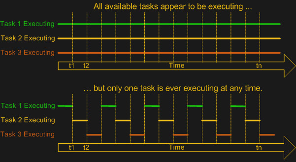
As FreeRTOS demonstrates, the primary point of adding an OS is to add multi-tasking (and multi-threading) support. This means a scheduler module that can use some kind of scheduling mechanism to chop the processor time into ‘slices’ in which different tasks, or threads can be active. While the easiest multi-tasking scheduler is a cooperative-style one, where each thread voluntarily yields to let other threads do their thing, this has the distinct disadvantage of each thread having the power to ruin everything for other threads.
 Most real-time OSes instead use a preemptive scheduler. This means that application threads have no control over when they get to run or for how long. Instead, an interrupt routine triggers the scheduler to choose the next thread for execution, taking care to differentiate between which tasks are preemptable and which are not. So-called kernel routines for example might be marked as non-preemptable, as interrupting them may cause system instability or corruption.
Although both Windows and Linux, in their usual configuration, use a preemptive scheduler, these schedulers are not considered suitable for real-time performance, as they are tuned to prioritize for foreground tasks. User-facing tasks, such as a graphical user interface, will keep operating smoothly even if background tasks may face a shortage of CPU cycles. This is what makes some real-time tasks on desktop OSes such a chore, requiring various workarounds.
A good demonstration of the difference with a real-time focused preemptive scheduler can be found in the x86 version of the QNX RTOS. While this runs fine on an x86 desktop system, the GUI will begin to hang and get sluggish when background tasks are performed, as the scheduler will not give the foreground tasks (the GUI) special treatment. The goal of the Linux kernel’s real-time patch also changes the default behavior of the scheduler to put the handling of interrupts first and foremost, while otherwise not distinguishing between individual tasks unless configured to do so by explicitly setting thread priorities.
RTOS or Not, That’s the Question
At this point it should be clear what is meant by “real-time” and you may have some idea of whether a project would benefit from an RTOS, a plain OS, or an interrupt-driven ‘superloop” approach. There’s no one-size-fits-all answer here, but in general one seeks to strike a balance between the real-time performance required and the available time and budget. Or in the case of a hobby project in far how one can be bothered to optimize it.
The first thing to consider is whether there are any hard deadlines in the project. Imagine you have a few sensors attached to a board that need to be polled exactly at the same intervals and the result written to an SD card. If any kind of jitter in between readings of more than a few dozen cycles would render the results useless, you have a hard real-time requirement of that many cycles.
We know that the underlying hardware (MCU, SoC, etc.) has either a fixed or worst-case interrupt latency. This determines the best-case scenario. In the case of an interrupt-driven single loop approach, we can likely easily meet these requirements, as we can sum up the worst-case interrupt latency, the cycle cost of our interrupt routine (ISR) and the worst-case time it would take to process and write the data to the SD card. This would be highly deterministic.
In the case of our sensors-and-SD-card example, the RTOS version would likely add overhead compared to the single loop version, on account of the overhead from its scheduler. But then imagine that writing to the SD card took a lot of time, and that you wanted to handle infrequent user input as well.
With an RTOS, because the samples need to be taken as close together as possible, you’d want to make this task non-preemptable, and give it a hard scheduling deadline. The tasks of writing to the SD card and any user input, with a lower priority. If the user has typed a lot, the RTOS might swap back to handling the data collection in the middle of processing strings, for instance, to make a timing deadline. You, the programmer, don’t have to worry about it.
In short: an RTOS offers deterministic scheduling, while an interrupt-driven single loop eliminates the need for scheduling altogether, aside from making sure that your superloop turns around frequently enough.
Creature Comforts
When one pulls away the curtain, it’s obvious that to the processor hardware, concepts like ‘threads’ and thread-synchronization mechanisms such as mutexes and semaphores are merely software concepts that are implemented using hardware features. Deep inside we all know that a single-core MCU isn’t really running all tasks simultaneously when a scheduler performs its multi-tasking duty.
Yet an RTOS – even a minimalistic one like FreeRTOS – allows us to use those software concepts on a platform when we simultaneously need to stay as close to the hardware as possible for performance reasons. Here we strike the balance between performance and convenience, with FreeRTOS leaving us to our own devices when it comes to interacting with the rest of the system. Other RTOSes, like NuttX, QNX and VxWorks offer a full-blown POSIX-compatible environment that supports at least a subset of standard Linux code.
While it’s easy to think of FreeRTOS for example as an RTOS that one would stuff on an MCU, it runs just as well on large SoCs. Similarly, ChibiOS/RT happily runs on anything from an 8-bit AVR MCU to a beefy x86 system. Key here is finding the right balance between the project requirements and what one could call creature comforts that make developing for the target system easier.
For RTOSes that also add a hardware abstraction layer (e.g. ChibiOS, QNX, RT Linux, etc.), the HAL part makes porting between different target systems easier, which can also be considered an argument in its favor. In the end, however, whether to go single loop, simple RTOS, complicated RTOS or ‘just an OS’ is a decision that’s ultimately dependent on the context of the project.
source https://hackaday.com/2021/02/24/real-time-os-basics-picking-the-right-rtos-when-you-need-one/


 (@nburdy)