Quadcopters have incredible flying abilities, but if one loses just a single motor, it drops like a rock. Researchers from the University of Zurich’s Robotics and Perception Group have proven that this does not need to be the case by keeping a quadcopter flying with only three motors.
A quadcopter usually has enough thrust to stay aloft with only three motors, but it will spin uncontrollably in the yaw axis. It is impossible to stop a quadcopter from spinning, so the focus for researchers was on keeping the drone controllable while it’s spinning. To achieve this, accurate position and motion estimation is required, so they attached a pair of cameras to the bottom of the craft for visual-inertial odometry (VIO). One is a normal optical camera, while the other is an event camera, which has pixels that can independently respond to changes in light as they occur. This means that it has better low light performance and does not suffer from motion blur.
The feeds from the cameras are analyzed in real-time by an onboard Nvidia Jetson TX2 for state estimation, which is then used with an optical range sensor and onboard IMU to maintain controlled flight, as demonstrated in the video after the break. The research paper is free to read, and all the code is available on GitHub.
Randonauting is the pastime of using random numbers to generate a destination to visit, in the pursuit of adventure. Of course, anything that can be done on a website with a script is even cooler with custom hardware, so [Decker] built a rig for the job.
The device uses a USB hardware random number generator to produce truly random numbers through quantum effects; at least, according to our best theories of the universe. These numbers are then used to pick a random set of GPS coordinates and a time in which to be there, a fun twist on traditional Randonauting of [Decker]’s own creation.
At its heart, it’s a random number generator pumped through some Python scripts. Where this build elevates itself is not in the mechanics, but the presentation. The rig runs on a Raspberry Pi, inside a bell jar, with a vacuum fluorsecent display, fairy lights and plumbing components. It plays on the cyberpunk aesthetic, and it’s so much harder to ignore one’s mission when the time and place are given in glowing numerals by an enigmatic, mysterious machine.
The leading cause of xenotransplant rejection is a sugar called alpha-gal. This sugar appears on the cell surfaces of all non-primate mammals. Alpha-gal is problematic for other reasons, too: a condition called alpha-gal syndrome usually begins when a Lone Star tick bites a person and transmits alpha-gal cells from the blood of animals they have bitten. From that point on, the person will experience an allergic reaction when eating red meat such as beef, pork, and lamb.
Pigs with Purpose
A litter of lifesaving piglets. Image via Revivicor
More people need a kidney than any other organ, so the company plans to start human trials with kidneys and move on to heart transplants in the future. In December 2020, the Food and Drug Administration (FDA) certified these so-called GalSafe pigs as fit for human consumption and therapeutic use. Although Revivicor doesn’t intend to produce GalSafe pigs for an allergy-free alternative for people with alpha-gal syndrome anytime soon, the door is certainly open for other companies to do so.
In 2016, Revivicor and researchers from the National Institutes of Health reported that they had been able to keep pigs’ hearts alive inside baboons for two and a half years. However, these weren’t direct transplant situations — the baboons kept their original hearts and hosted the pigs hearts in their abdomens.
Genetically modified alpha-gal-free pigs could help the organ transplant crisis, though it’s unclear at this point how long the organs will last once transplanted into humans. Revivicor and United Therapeutics hope they can last the rest of a person’s life, or at least long enough until they can get a human organ to replace it. Even if this only ends up being a stopgap until a better alternative arives, it could save many lives. What do you think?
The basic test instrument suite — a bench power supply, a good multimeter and perhaps an oscilloscope — is extremely flexible, but not exactly “plug and play” when it comes to diagnosing problems with some common hardware setups. A problem with a servo driver, for example, might be easy enough to sort of with a scope, but setting everything up to see what’s going on with the PWM signal takes some time.
There’s got to be a better way to diagnose hobby electronics woes, and if [Bob Alexander] has his way, his “Logic Meter”, or something very close to it, will be the next must-have bench tool. The Logic Meter combines some of the functionality of an oscilloscope and a logic analyzer into a handy instrument that’s as easy to use as a multimeter. The Logic Meter’s probes connect to logic-level signals in a circuit and can be set up to capture or send serial data, either directly to or from a UART or via an SPI bus connection. There are also functions for testing servos and similar devices with a configurable PWM output. [Bob] rounds out the functionality with a GPS simulator and a simple logic analyzer, plus some utility functions.
The beauty part of the Logic Meter is that [Bob] has left where it goes next largely up to the community. He’s got a GitHub repo with details on the PIC32-based hardware, and the video below makes it clear that this is just a jumping-off point to further work that he hopes results in a commercial version of the Logic Meter. That’s a refreshing attitude, and we hope it pays off; from the look of a few of [Bob]’s retrocomputing makeovers, something like the Logic Meter could come in pretty handy.
When it was first announced, many people were skeptical of the Nintendo DS. Rather than pushing raw power, the unique dual screen handheld was designed to explore new styles of play. Compared to the more traditional handhelds like the Game Boy Advance (GBA) or even Sony’s PlayStation Portable (PSP), the DS seemed like huge gamble for the Japanese gaming giant.
But it paid off. The Nintendo DS ended up being one of the most successful gaming platforms of all time, and as [Modern Vintage Gamer] explains in a recent video, at least part of that was due to its surprising graphical prowess. While it was technically inferior to the PSP in almost every way, Nintendo’s decades of experience in pushing the limits of 2D graphics allowed them to squeeze more out of the hardware than many would have thought possible.
On one level, the Nintendo DS could be seen as a upgraded GBA. Developers who were already used to the 2D capabilities of that system would feel right at home when they made the switch to the DS. As with previous 2D consoles, the DS had several screen modes complete with hardware-accelerated support for moving, scaling, rotating, and reflecting up to four background layers. This made it easy and computationally efficient to pull off pseudo-3D effects such as having multiple backdrop images scrolling by at different speeds to convey a sense of depth.
On top of its GBA-inherited tile and sprite 2D engine, the DS also featured a rudimentary GPU responsible for handling 3D geometry and rendering. Hardware accelerated 3D could only used on one screen at a time, which meant most games would keep the closeup view of the action on one display, and used the second panel to show 2D imagery such as an overhead map. But developers did have the option of flipping between the displays on each frame to render 3D on both panels at a reduced frame rate. The hardware can also handle shadows and included integrated support for cell shading, which was a particularly popular graphical effect at the time.
By combining the 2D and 3D hardware capabilities of the Nintendo DS onto a single screen, developers could produce complex graphical effects. [Modern Vintage Gamer] uses the example of New Super Mario Bros, which places a detailed 3D model of Mario over several layers of moving 2D bitmaps. Ultimately the 3D capabilities of the DS were hindered by the limited resolution of its 256 x 192 LCD panels; but considering most people were still using flip phones when the DS came out, it was impressive for the time.
Compared to the Game Boy Advance, or even the original “brick” Game Boy, it doesn’t seem like hackers have had much luck coming up with ways to exploiting the capabilities of the Nintendo DS. But perhaps with more detailed retrospectives like this, the community will be inspired to take another look at this unique entry in gaming history.
Space is hard, especially if you haven’t done it before. A growing number of CubeSats are launched by small, inexperienced teams every year, and a number of them fail due to missing some small but critical hardware or software problem. Researchers from the Robotic Exploration Lab (REx) at Carnegie Melon University have learned some of these lessons the hard way and created PyCubed, an open-source hardware and software framework for future CubeSats.
Most satellites, including CubeSats, require the same basic building blocks. These include ADCS (Attitude Determination and Control System), TT&C (telemetry, track, and command), C&DH (command and data handling), and an EPS (electrical power system). Each of these building blocks is integrated into a single PC/104 size PCB. The main microcontroller is an ATSAMD51, also used on a couple of Adafruit dev boards, and runs Circuit Python. Communications are handled by a LoRa radio module, and there is also an unpopulated footprint for a second radio. An LSM9DS1 IMU and an optional GPS handle navigation and attitude determination, and a flash chip and micro SD card provide RAM and data storage. The EPS consists of an energy harvester and battery charger, power monitor, and regular, that can connect to external Li-Ion batteries and solar panels. Two power relays and a series of MOSFETs connected to burn wires are used to deploy the CubeSat and its antennas.
On the PCB there are standardized footprints for up to four unique payloads for the specific missions. The hardware and software are documented on GitHub, including testing and a complete document on all the design decisions and their justifications. The PyCubed was also presented at the 2019 AIAA/USU Conference on Small Satellites. The platform has already been flight-tested as part of the Kicksat-2 mission, and will also be used in the upcoming V-R3X, Pandasat, and Pycubed-1 projects.
This is not the first open-source CubeSat we’ve seen, and we expect these platforms to become more common. Tracking a CubeSat is a lot less expensive than sending one to space, and can be done for as little as $25.
If you want to waste time in a meaningful way, get yourself an hourglass. It’s simultaneously mesmerizing and terrifying to sit there and watch the seconds slip through the threshold that separates possibility from missed opportunity.
[Ty and Gig]’s LED hourglass is equally beautiful to watch. It doesn’t actually tell time, but that’s perfectly fine by us. What it does do is animate the LEDs to approximate grains of sand in gravity, no matter how the hourglass is tilted.
In either vertical orientation, the sand falls as long as there is some in the top. When the hourglass is horizontal, the LEDs settle just like real sand does. [Ty and Gig] achieved this with a whole lot of code that breaks the animation frames into structure arrays.
By contrast, the hardware part of this build is fairly simple: all that’s needed to replicate this build is some RGB LEDs a beefy power supply to drive them, an accelerometer, and a microcontroller.
[Ty and Gig] were planning to use an ESP8266, but misplaced it and went with an Arduino Mega instead. (You know what they say — buy a replacement and the one you lost will turn up almost immediately.) The beautiful frame is made from leftover purpleheart, a hardwood that turns purple with exposure to air. Check out the build video after the break.
The Apple Watch was the tech company’s attempt to bring wrist computers into the mainstream. It’s naturally available in a variety of fits and finishes, but if you want something properly original, you’ve got to go custom. [Useless Mod] does just that with a clear case for the popular smartwatch.
The mod starts with a patient, careful disassembly of the watch – necessary given the delicate components inside. It’s achieved in the end with only having to drill out 1 screw and an unfortunately snapping of the crown wheel axle. However, [Useless Mod] presses on, and silicone casts the original Apple enclosure. The video goes over all the finer points, from degassing to using strips of acrylic plastic to act as runners. Once done, the silicone mold is used to produce a replica case in transparent epoxy, and the watch is reassembled.
The final result is impressive, with the case optically clear and showing off the watch’s internals. The look is improved by removing some of the original insulation tape to better reveal the PCBs inside. Unfortunately, the design of the watch, which is largely covered by a screen and heartbeat sensor, means it’s not the greatest choice for a clear case mod, but it works nonetheless. We’ve seen similar work before from [Useless Mod] too – like this transparent drone case for the Mavic Mini. Video after the break.
You’d be forgiven for thinking that receiving data transmissions from orbiting satellites requires a complex array of hardware and software, because for a long time it did. These days we have the benefit of cheap software defined radios (SDRs) that let our computers easily tune into arbitrary frequencies. But what about the software side of things? As [Dmitrii Eliuseev] shows, decoding the data satellites are beaming down to Earth is probably a lot easier than you might think.
Well, at least in this case. The data [Dmitrii] is after happens to be broadcast from a relatively old fleet of satellites operated by the National Oceanic and Atmospheric Administration (NOAA). These birds (NOAA-15, NOAA-18 and NOAA-19) are somewhat unique in that they fly fairly low and utilize a simple analog signal transmitted at 137 MHz. This makes them especially good targets for hobbyists who are just dipping their toes into the world of satellite reception.
[Dmitrii] doesn’t spend a lot of time talking about the hardware in this post, only to say that he’s using a SDRPlay with what he describes as a poor antenna. He provides a link for information on building a more suitable antenna, but the signal is strong enough that an old set of “Rabbit Ears” will do in a pinch. From there he goes over how you can predict when one of the NOAA birds will be passing overhead, and explains how to configure your SDR software to capture the resulting signal. From there, it’s a step-by-step guide on how to make sense of the recorded WAV file.
With the help of the scipy library, it’s surprisingly easy to load the WAV file and generate some visualizations of the signal within. Since it’s analog, it only takes a bit more work with the Python Imaging Library (PIL) to convert that into a 2D image. [Dmitrii] notes that using the putpixel function isn’t the most efficient way to do this, and gives some tips on how you could speed up the process greatly, but for the purposes of the demonstration it makes for more easily understood code.
As much as we love Star Trek, we have to admit there are some continuity problems. For example, in Spock’s Brain, the alien-of-the-week’s ion drive gave Scotty engineering envy. However, in The Menagerie, the computer identifies a Starfleet shuttlecraft as having ion propulsion. Either way, ion propulsion is real and NASA has toyed with it for ages and many satellites use it for maintaining orbit. Now researchers from MIT and the Monterrey Institute of Technology and Higher Studies 3D printed tiny ion engines.
The engine is about the size of a dime and, like all ion engines, produces tiny amounts of thrust. In fact, the researchers liken it to half the weight of one sesame seed from a hamburger bun. However, in space, these tiny thrusts add up and over time can produce significant acceleration.
The full paper is available and shows the device operates electrohydrodynamically, creating a fine spray of charged particles. Interestingly, the device is capable of creating fine sprays of liquid or nanofibers, so the applications aren’t just for space vehicles. However, the researchers were actually surprised that the device creates a pure ion jet and they aren’t entirely sure how the device works.
The device has a reservoir of liquid with an array of emitter cones. The cones are coated with zinc oxide nanowires that act as wicks to transfer the liquid to the emitter tips where the liquid is ionized and expelled. The researchers think the nanowires are responsible for the creation of the pure jet of ions.
When it comes to building quirky clocks that also double up as beautiful animated sculptures, [Ekaggrat Singh Kalsi] is a master par excellence. His latest offering is the Getula, a time piece inspired by an old, discarded bicycle chain, while the name seems inspired by the chain kingsnake — Lampropeltis getula – due to its snake like movements. Getula shows time by manipulating eight short pieces of chain to show four digits representing hours and minutes. But wrangling a flexible piece of chain to morph in to numerals turned out to be a far more complex endeavour than he bargained for, and he had to settle for a few compromises along the way.
He could not use real bicycle chains because they are too flexible and heavy, which made it impossible for them to hold the shapes he desired. Instead, he designed custom 3D printed chains similar to drag link chains used for cable management. For rigidity, he added O-rings in the chain joints to increase friction. But even this was not sufficient to completely form each digit using a single piece of chain.
The compromise was to use two pieces of chain per digit, which results in a more artistic expression of time keeping. Each piece of chain is pushed or pulled using stepper motors, and bent in to shape using servos. The end result is a mesmerising dance of chain links, steppers and servos every minute, around the clock.
Designing the clock was no trivial exercise, so [Ekaggrat] improved it over a couple of iterations. There are four modular blocks working in synchronism — each consisting of an Arduino Nano, two stepper motor drives with motors and two servos. Each chain has an embedded magnet at its start, which is sensed by a hall sensor to initialise the chain to a known position. A DS1307 RTC module provides timekeeping. The project is still work in progress, and [Ekaggrat] has managed to finish off just one module out of four — giving us a tantalizing glimpse of Getula welcoming 2021.
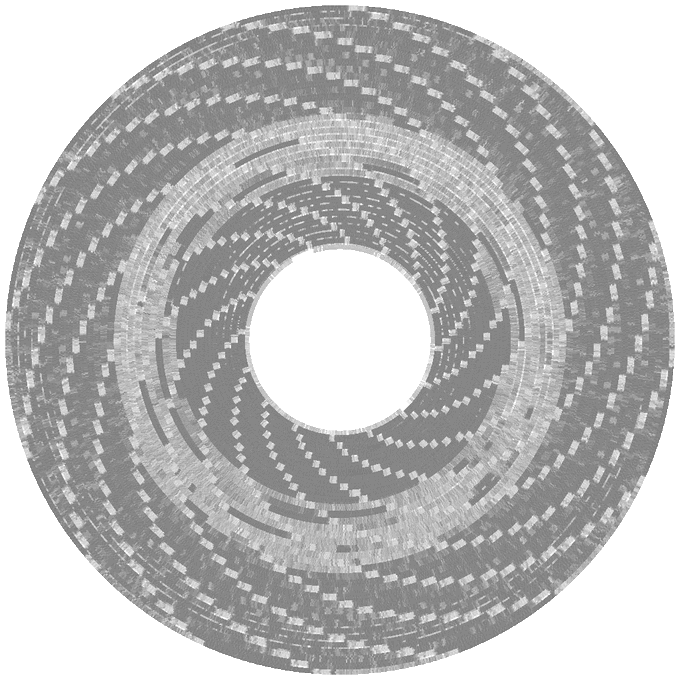
Back in 1990 [Benjamin Zotto] wrote – while in elementary school – a dog racing game called Wonderland 2. The BASIC source code and images for the game were stored on a single ProDOS formatted, soft-sectored 5.25″ floppy disk. Fast-forward thirty years to today and [Benjamin] found to his dismay that ProDOS could no longer read the floppy, giving an I/O error. Not deterred, he set about to recover the data, as documented in this Twitter thread.
Applesauce visualization of the patterns on the corrupted disk, with soft-sectoring spiral arms.
The gist of the story is that the floppy disk’s surface could still be scanned with help from the aptly named Applesauce Floppy Drive Controller, which got the following visualization of the magnetic patterns on the disk surface:
This data could then be analyzed sector by sector, with the bad sectors and the cause for ProDOS flaking out with its reading attempts here marked in red.
Checking the data recovered so far confirmed that it was a ProDOS disk. It also confirmed that the sector containing the directory listing was shot. This required diving into the technical reference manual for ProDOS and its filesystem to figure out how to reconstruct the directory layout. This required figuring out the offsets and sizes of the files, assisted by knowing what was likely on the disk, and having some bits and pieces of the original volume listing still intact. This allowed for the directory volume to be rebuilt, one byte at a time.
Sectors on the disk, with bad sectors in red.
At the end of that arduous and highly educational journey success waited, and [Benjamin] was once again able to relive his memories of 1990s BASIC and hand-drawn bitmap graphics.
There is a boring part of every computer introduction class that shows how a computer is made up of input, output, and processing. Maybe it wouldn’t be so boring if the input device was a nunchuck. [Brian Lough] thinks so and he belligerently asserts that nunchucks are the best input device ever. With a simple connection to a Wii controller and an associated library, you get access to an analog joystick, two buttons, and an accelerometer.
The nunchuck is meant to plug into a Wii controller and the connection is I2C, so that’s trivial to interface to an Arduino or other small microcontroller. The only issue is making the connection. We might have just snipped the wires, but [Brian] prefers to use a small breakout board that plugs into the stock connector and provides solder points for your own cable. There are options for the breakout boards, and [Brian] has his own design that you can get from OSHPark for about a buck for three boards. You can also just jam wire into the connector, but that’s not always robust.
The controllers use 3.3V which isn’t unusual these days. There’s an available library that makes reading them easy. Obviously, not all applications will be a natural fit, but we did like them on the Tetris game [Brian] created. It is also natural for any kind of motion control like his gimbal mount example.
Even if you don’t have junk Wii controllers hanging around, they are common enough on the resale market and you can buy new third-party controllers without spending much. Makes us sorry we threw away ours in the last move.
If you want to get serious hacking a nunchuck, you can go full custom. Or, just give up, and turn one into a Raspberry Pi.
We’re not sure what we like better about this upcycled trapper hat — that [ellygibson] made it as a tribute to Holden Caulfield, the anti-hero of the classic teen angst novel The Catcher in the Rye, or the fact that she made it out of a skirt that cost a dollar from the thrift store. Oddly enough, one dollar is exactly what Holden paid for his hat in the book.
To make this hat, [elly] started by measuring the circumference of her head, then used math to figure out the radius of the circle for the top part. She made a prototype first to get the fit right, then cut the pieces from the skirt and the lining pieces from black flannel. We love that [elly] used the tiny pocket from the skirt in one of the ear flaps, because it will surely come in handy one day.
[elly] doesn’t provide pattern pieces, but that’s okay — between the explanation of how she arrived at the hat band circumference and the step-by-step instructions, it should be easy to make one of these for yourself from whatever fabric you’ve got.
[Carl] wanted to put his force sensors on a transparent PCB and had to ask his board vendor for a special sample. Flexible PCBs are available on transparent substrates made of PET, but they are not as common as polyimide boards. As [Carl] found out, these boards are a bit thicker, a bit less flexible, and don’t hold up to very high heat as well as the standard boards. Undeterred, he designed a 3D Christmas tree using the clear boards. The result that you can see in the video below looks pretty good and would have been hard to duplicate with conventional means.
When you build the board it is as a flat spiral, but lifting it in the center allows it to expand into a conical tree shape. The circuit itself is just an LED blinker, but the flexible board is the interesting part.
Don’t let the heat put you off, as though the boards deformed at temperatures around 215C and require careful soldering, your projects will probably not run at that temperature.
There was a time when any sort of flexible PCB was a big project. Now it is easily done and not particularly expensive. [Carl] mentions he violates some best practices for the sake of speed and aesthetics, but the result works fine and it looks pretty cool.
We know what you’re thinking. It’s a bad power supply, of course it was capacitors to blame. But even if we all intuitively know at this point that bad caps are almost always the culprit when a PSU gives up the ghost, it’s not always easy to figure out which one is to blame. Which is why this deep dive into a failed ETK450AWT by [eigma] is worth a look.
The first sign of trouble was when the computer would unexpectedly reboot with nothing in the system logs to indicate a problem. Eventually, [eigma] noticed a restart before the operating system even loaded, which confirmed the hardware was to blame. A quick look at the PSU output with a voltmeter showed things weren’t too far out of spec, but putting an oscilloscope on the 12 V line uncovered a nasty waveform that demanded further investigation.
Connecting all the dots.
By carefully following traces and comparing with common PSU diagrams, [eigma] was able to identify the SG5616 IC that checks the various voltages being produced by the PSU and generates the PWR_OK signal which tells the motherboard that everything is working normally. As before, all of the DC voltages at this chip seemed reasonable enough, but the pin that was measuring AC voltage from the transformer was showing the same ripple visible on the 12 VDC line.
Even more digging uncovered that the transformer itself had a control IC nestled away. The 13 VDC required by this chip to operate is pulled off the standby transformer by way of a Zener diode and a couple capacitors, but as [eigma] soon found, the circuit was producing another nasty ripple. Throwing a few new capacitors into the mix smoothed things out and got the PSU to kick on, but that’s not quite the end of the story.
Pulling the capacitors from the board and checking their values with the meter, [eigma] found they too appeared to be within reasonable enough limits. They even looked in good shape physically. But with the help of a signal generator, he was able to determine their equivalent series resistance (ESR) was way too high. Case closed.
Even if you aren’t an electronics person, you probably have a working knowledge of circuit breakers. When the lights go out, you find the circuit breaker and flip it back to the on position. Most people understand, too, that the breaker will trip if you overload the circuit with too many things plugged in or with an accidental short circuit. But how does this common device actually work? Keep in mind, circuit breakers need to be super reliable and have been around long enough that you can imagine they are pretty low tech. [Learn Engineering] has a very clear video about what goes on inside a circuit breaker that’s worth the eight minutes to watch. You can see the video below.
The handle is a mechanical engineering marvel, using two springs and a special design so that even a tiny force will cause it to snap to the off position. That takes care of a human tripping it. However, you have two other cases where you want to turn it off: overload and short circuit.
The short circuit case is easy to detect with an electromagnet that will have a strong magnetic field when so much current flows. However, the overload case isn’t that abrupt. For that, the breaker uses a bimetalic coil that expands as it heats.
There is one other detail. When the breaker opens at high currents, an arc forms. There’s a special component inside to help dissipate the arc. There’s a lot going on in that little box.
Of course, nowadays there are fancier breakers that detect arcing as well as shorts and overloads. We’ve also seen at least one other breaker teardown in the past.
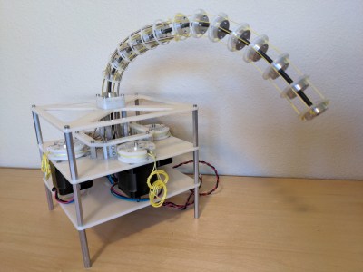
I fell in love with cable driven mechanisms a few years ago and put together some of my first mechanical tentacles to celebrate. But only after playing with them did I start to understand the principles that made them work. Today I want to share one of the most important equations to keep in mind when designing any device that involves cables, the capstan equation. Let some caffeine kick in and stick with me over the next few minutes to get a sense of how it works, how it affects the overall friction in your system, and how you can put it to work for you in special cases.
A Quick Refresher: Push-Pull Cable Driven Mechanisms
But first: just what exactly are cable driven mechanisms? It turns out that this term refers to a huge class of mechanisms, so we’ll limit our scope just to push-pull cable actuation systems.
These are devices where cables are used as actuators. By sending these cables through a flexible conduit, they serve a similar function to the tendons in our body that actuate our fingers. When designing these, we generally assume that the cables are both flexible and do not stretch when put in tension.
Since these cables are flexible, they can only exhibit a pull force, not a push, so cables often come in pairs to actuate along both directions. Here, they’ll be opening and closing the jaws of the Chomper.
Here, the joystick controls the yellow jaw of our Chomper by means of two cables, either of which can be put in tension. One of the key elements behind cables is the ability to reroute the direction of the applied force by controlling the cable through thin sheaths or conduits like so:
In this setup above, we can still control the Chomper remotely through the joystick and the mechanical control cables, albeit, with some added friction. Ideally, the conduits routing the cable are extremely flexible and do not compress when a compressive force is applied to them. That might sound like sort of magic component–but it’s not! It’s actually just a long skinny extension spring like these parts from DR Templeman. These parts go by a few names: continuous-length extension spring, spring guide… but I’ll generally refer to them as spring guide when referring to them in animatronics projects. This spring guide is extremely flexible, but also resistant to being compressed since it’s made from stainless steel.
If the above example seems a bit far-fetched, take the braking system on your bicycle as an example of a cable-actuated setup. Here, your hand squeezes the brakes on one end of the bike, which moves a length of cable running through a sheath on your bike, which moves your brake calipers and eventually squeezes the rim of your wheel hub to slow you down. Instead of a second conduit, however, an extension spring provides the return force to open the brake calipers when we release the handle.
All in all, these mechanisms really shine in situations requiring tight clearances, backlash-free control, and a limited angle of rotation. Properly designed, cable drives can be made to be both backlash free and back-drivable. But they’re no miracle elixir here. They have limits, and the capstan equation is fundamental to understanding your biggest challenge when it comes to their design: friction.
You vs. Friction: Conduit Edition
Wouldn’t it be neat if we could control anything remotely, using mechanical control cables from a distance? I totally agree! But it’s worth asking, what’s preventing us from weaving our cable and conduit in and out of some arbitrary setup? The answer comes down to friction. Friction is our enemy here, putting a limit to how much we can physically bend the conduit before it becomes too difficult to move. But the specific relationship to our problem is rather unintuitive! To build up a rigorous understanding of how friction affects the cable, let’s start by working a sample problem.
Let’s get rid of the conduit for a minute and start with a crude model using just two ingredients: a cable and a cylinder. In the image below, we’ve wrapped the cable partially around a fixed cylinder, and we’ve put both ends of the cable in tension so that the cable hugs the cylinder. Keep in mind that the cylinder can’t rotate, so if we wanted to move the cable, we’d have to fight friction here and rub up against the cylinder.
Now let’s start by putting both sides in tension with two tension values: TLoad and THold. We’ll keep the tension constant on THold, but let’s slowly increase value of TLoad. If our cylinder were actually frictionless pulley, trying to create a mismatch in tension would be impossible; the tension on one side would always be equal to the tension on the other side. But because our cylinder is fixed, it is, in fact, possible to increase the tension on one side while keeping the tension on the other side constant, all while the rope doesn’t slip in the process. This happens because static friction on the cylinder is acting against the tension increase up to a certain limit.
If we zoom in on a cross section of rope to examine the forces acting on a small sliver, we can see how static friction is acting against TLoad, which is equalizing the tension mismatch so that the cable doesn’t slip.
Free body diagram of an infinitesimal cross section of cable measuring with infinitesimal angle dθ.
So here’s the big question: for a fixed value of THold on one side of the cylinder, just how much am I allowed to increase the TLoad on the other side before the cable slips and starts rubbing on the cylinder? (Heads-up! The full derivation requires some calculus and differential equation knowledge, but, for the curious, have a look at this PDF.)
TL;DR: the answer is the Capstan Equation. It tells us that, for a given holding tension on one side, the maximum amount of tension we can put on the other side of the cable without slipping is given by:
Moving both T’s over to one side gives us something a little more interesting: a ratio between two tensions.
Let’s have a look at this equation’s inputs. µs is the cable’s coefficient of static friction, a material property that we can look up in a table or material datasheet. θ is the total bend angle between your two tension vectors, TLoad. and THold, measured in radians. TL and TH are the magnitudes of each respective tension value.
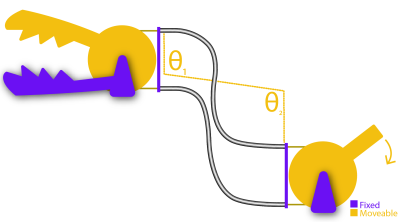
Also, an important side note: the bend angle θ is cumulative. In other words, if you add another fixed cylinder into the mix, you have to add up the total bend angle there too. That’s true even if the angle bends in the opposite direction as shown below:
So the total angle that we’d put in the capstan equation is given by θ1+ θ2.
What’s key here is that only two properties, bend angle and coefficient of static friction, will dictate just how much extra tension we can add on one side before the whole setup slips. So what can we glean from this equation?
The first key takeaway is that the cylinder size has no effect on the amount of friction mismatch. In other words, a small radius cylinder will produce the same resulting value that a large radius cylinder would, provided that the overall bend angles are the same. That’s not intuitive! I should mention, though: the equation above assumes that the cable is infinitely flimsy, which is a good approximation unless our bending radius is really small, like a few multiples of the cable diameter. In that case, the force required to bend the cable does matter. But, for most situations, we can ignore it.
Another key takeaway is that the relationship is exponentially related to the bend angle! So while one wrap around the cylinder might not add much friction, adding a second wrap more-than-doubles the maximum tension ratio between the two cable ends. For an example, with a cable who’s µs = 0.3, two wraps is 6.6 times more friction than one wrap. Three wraps is 43.4 times more friction than one wrap [math link]. But if our µs = 0.2, than three wraps is only 12.3 times as much friction as one wrap. In short, exponential relationships are not intuitive and add up quickly, and picking a cable with a coefficient of friction that’s as small as possible (like this nylon-coated cable) is key to keeping the excess friction low.
On its own, this example feels pretty obtuse, so let’s tie it back to our original problem with our cable-driven chomper using conduits. To translate the takeaways from problem to our setup, we simply substitute the cylinders above with conduit, and–voila–the exact same equation applies to this setup also! Since both the cylinder and the conduit are fixed, the capstan equation applies to this situation too. Here the cumulative bend angle is coming from the total bend of the cable that’s in tension.
Notice that I only marked angles θ1 and θ2 on one conduit, not both. That’s on purpose. For a for a clockwise torque applied to the joystick, only one cable is being put in tension; the other one goes slack. In other words, only the bends on the cable in tension add to the friction cost. If we applied a torque on the handle in the other direction, the friction costs would come from the bends in the other conduit. In practice, we’d probably route both of these conduits together as a single bundle, but it’s important to realize exactly who’s responsible for the friction depending on the direction of the input.
Designing Around Friction Costs
Applied to our Chomper setup, the Capstan Equation tells us just how much harder we have to tug on one side of the cable before we can get the other side of the cable to start moving. If we know the our cable’s coefficient of static friction and can estimate the max bend angle of our setup, we can estimate the maximum tension value our setup will ever encounter, which, in turn, helps us spec a motor with the appropriate amount of torque.
But there’s another, even simpler takeaway from this equation that we can use as a general rule of thumb. When it comes to designing your own cable driven mechanisms that use conduit, we want to remove any unnecessary bends anywhere else in the cable. In other words, conduits aren’t a catch-all solution for routing a pull force anywhere else in our system. Every bend that we add to them adds a friction cost, and that added friction can be computed with the capstan equation.
Now that we know how friction and bend angle are related, how could I adjust my design to reduce some of the unnecessary friction that the motors will need to fight through? (I confess that I didn’t know the capstan equation when I made this setup.)
If your system needs to route cable through a host of bends, consider introducing pulleys to do some of these bends for you. Since pulleys roll freely, they don’t add friction, and, therefore, do not contribute to the cumulative bend angle in the capstan equation.
A Teaser: The Inverse Problem
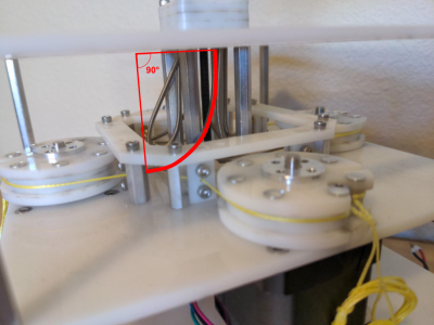
A Capstan Drive. Project Credit: Wooden Haptics
While the Capstan Equation is a huge bummer for preventing us from endlessly weaving our conduit through hard-to-reach sections of our design, a few cases exist where that friction is extremely useful. Since the tension on one side is exponentially related to the tension on the opposite side, with only about four wraps, we can actually use the capstan cylinder to drive the cable directly without worrying about the wire slipping.
This marvelous property gives way to a mechanism called a capstan drive, a cable wrapped around a small shaft that can be used as an actuator. Here, we’ve put the Capstan Equation to work. We’re counting on that exponential relationship so that our cable doesn’t slip while the cylinder is rotated. These mechanisms are just too cool to gloss over, so we’ll revisit them in a future post. Until then, we hope this brief intro helps you think a bit more carefully about routing cables in your next push-pull cable conduit project, tentacles included or not.


 Now let’s start by putting both sides in tension with two tension values: TLoad and THold. We’ll keep the tension constant on THold, but let’s slowly increase value of TLoad. If our cylinder were actually frictionless pulley, trying to create a mismatch in tension would be impossible; the tension on one side would always be equal to the tension on the other side. But because our cylinder is fixed, it is, in fact, possible to increase the tension on one side while keeping the tension on the other side constant, all while the rope doesn’t slip in the process. This happens because static friction on the cylinder is acting against the tension increase up to a certain limit.