
Yearly Archives: 2019
The Delusional Christian Gets Smashed Up by Atheist Matt Dillahunty in this God Debate
Difference between Wisdom and IQ? | Jordan Peterson, Bret Weinstein
r/JustNoHOA – YOU WANT TO SAVE LIVES? WE WILL TOW YOUR TRUCK INSTEAD! 👨🚒
Cat Diner Now Under New Management
Most of these stories start with a cat standing on someone’s chest, begging for food at some obscene hour of the morning. But not this one. Chaz the cat is diabetic, and he needs to get his insulin with breakfast. The problem is that Chaz likes to eat overnight, which ruins his breakfast appetite and his chances at properly metabolizing the insulin. [Becky] tried putting the bowl away before bed, but let’s face it — it’s more fun to solve a problem once than to solve the same problem every night.
[Becky]’s solution was to design and print a bowl holder with a lid, and to cover the bowl when the cat diner is closed using a small servo and a NodeMCU. It looks good, and it gets the job done with few components. Chaz gets his insulin, [Becky] gets peace of mind, and everybody’s happy. This isn’t going to work for all cats, because security is pretty lax. But Chaz is a senior kitty and therefore disinterested in pawing at the lid to see what happens. Claw your way past the break to see [Becky]’s build/demo video featuring plenty of cat tax coverage.
We’ve seen a lot of cat feeding apparatus around here, but few that solve a specific problem like this one. If it’s overengineering and cat metrics you want, come and get it.
source https://hackaday.com/2019/12/30/cat-diner-now-under-new-management/
36C3: SIM Card Technology From A to Z
SIM cards are all around us, and with the continuing growth of the Internet of Things, spawning technologies like NB-IoT, this might as well be very literal soon. But what do we really know about them, their internal structure, and their communication protocols? And by extension, their security? To shine some light on these questions, open source and mobile device titan [LaForge] gave an introductory talk about SIM card technologies at the 36C3 in Leipzig, Germany.
Starting with a brief history lesson on the early days of cellular networks based on the German C-Netz, and the origin of the SIM card itself, [LaForge] goes through the main specification and technology parts of each following generation from 2G to 5G. Covering the physical basics, I/O interfaces, communication protocols, and the file system located on the SIM card, you’ll get the answer to “what on Earth is PIN2 for?” along the way.
Of course, a talk like this, on a CCC event, wouldn’t be complete without a deep and critical look at the security side as well. Considering how over-the-air updates on both software and — thanks to mostly running Java nowadays — feature side are more and more common, there certainly is something to look at.
source https://hackaday.com/2019/12/30/36c3-sim-card-technology-from-a-to-z/
Focus Stacking For Tiny Subjects
Focus stacking is a photographic technique in which multiple exposures are taken of a subject, with the focus distance set to different lengths. These images are then composited together to create a final image with a greater depth of field than is possible with a single exposure. [Peter Lin] built a rig for accurate focus stacking with very small subjects.
The heart of the rig is a motion platform consisting of a tiny stepper motor fitted with a linear slide screw. This is connected to an Arduino or PIC with a basic stepper driver board. While the motor does not respond well to microstepping or other advanced techniques, simply driving it properly can give a resolution of 15 μm per step.
The motor/slide combination is not particularly powerful, and thus cannot readily be used to move the camera or optics. Instead, the rig is designed for photography of very small objects, in which the rail will move the subject itself.
It’s a tidy build that would serve well for anyone regularly doing macro focus stack photography. If you’ve been trying to better photograph your insect collection, this one is for you. It’s a valuable technique and one that applies to microscopy too. Video after the break.
source https://hackaday.com/2019/12/30/focus-stacking-for-tiny-subjects/
Jeremy Cook is Living His Strandbeest Dream
The first thing Jeremy Cook thought when he saw a video of Theo Jansen’s Strandbeest walking across the beach was how incredible the machine looked. His second thought was that there was no way he’d ever be able to build something like that himself. It’s a feeling that most of us have had at one time or another, especially when starting down a path we’ve never been on before.
But those doubts didn’t keep him from researching how the Strandbeest worked, or stop him from taking the first tentative steps towards building his own version. It certainly didn’t happen overnight. It didn’t happen over a month or even a year, either.
For those keeping score, his talk at the 2019 Hackaday Superconference, “Strandbeests: From Impossible Build to Dominating My Garage” is the culmination of over six years of experimentation and iteration.
His first builds could barely move, and when they did, it wasn’t for long. But the latest version, which he demonstrated live in front of a packed audience at the LA College of Music, trotted across the stage with an almost otherworldly smoothness. To say that he’s gotten good at building these machines would be something of an understatement.
Jeremy’s talk is primarily focused on his Strandbeest creations, but it’s also a fascinating look at how a person can gradually move from inspiration to mastery through incremental improvements. He could have stopped after the first, second, or even third failure. But instead he persisted to the point he’s an expert at something he once believed was out of his reach.
Learning to Crawl
There’s a well known Chinese proverb that, roughly translated, states “a journey of a thousand miles begins with a single step.” It’s something to keep in mind any time you take on a challenge, but it rings especially true for anyone looking to build a Strandbeest. Rather than trying to tackle the entire machine at once, Jeremy thought a reasonable enough approach to constructing a multi-legged walking robot was to first build a single leg and understand how it operates.
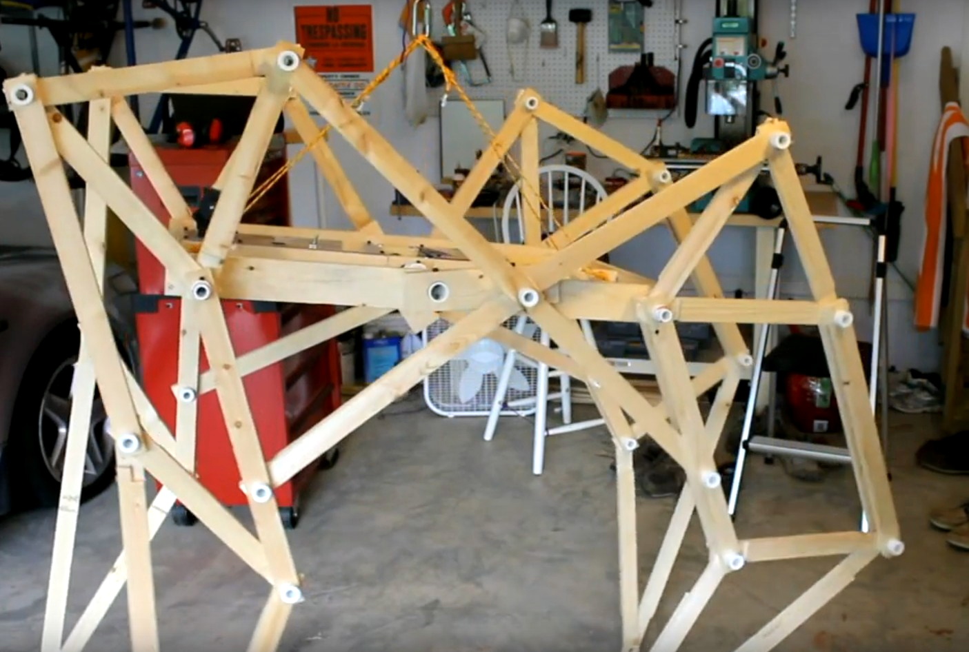
With one leg built and working, the next step was of course to build more of them. When he had four assembled, it was time to design a base to mount them on, and then outfit it with electric motors to get things moving.
Unfortunately this first Strandbeest, made of wood and roughly the size of a golf cart, never worked very well. Jeremy attributes its failure to a number of issues which he would eventually learn to solve, such as imprecision in the linkages, excessive friction, and undersized motors. That first build may have failed as a walker, but it served as a fantastic learning experience.
For the second Strandbeest Jeremy switched over to cutting the parts out of MDF, but the contraption was still too heavy. This version was even less successful than the first, and it soon fell apart. It seemed clear at this point that the way forward was to scale the design down to a more manageable size.
The Next Generation
Once he shrunk the walker’s design down to tabletop scale, Jeremy really started seeing some progress. It still took a few iterations to get something that could move around without jamming up or rattling itself to pieces, but with parts that could be accurately cut on a CNC router and the addition of a new geared drive system, these smaller Strandbeests really started to come alive.
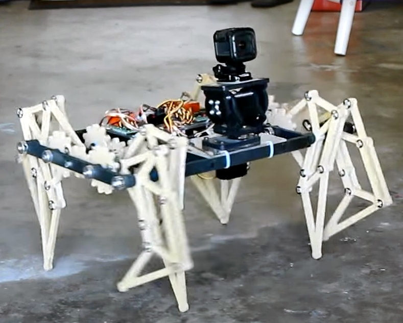
Not only did they perform much better, but the eventual switch to clear acrylic gave them a very distinctive look. Around this time, Jeremy also started to add some anthropomorphic features, like articulated “heads” that housed cameras or LED “eyes”. These features not only gave his bots the ability to emote, but also marked a clear separation between his creations and that of Theo Jansen, who’s designs were only getting larger and more alien as time went on.
The latest and greatest of these acrylic Strandbeests is the ClearCrawler, which takes into account all the lessons Jeremy has learned over the years. Powered by an Arduino Nano and controllable via a custom handheld remote using nRF24L01 modules, this walker is easily expandable and provides an excellent platform for further research and exploration.
Staying Humble
Despite the leaps and bounds that Jeremy has made with his Strandbeests, he still remains in awe of the original wind-powered walkers that Theo Jansen unveiled all those years ago. If anything, he says he has more respect for those creations now than when he first saw them. Looking at it with no knowledge of how it works, you’ll of course be impressed. But once you understand the mechanisms involved, and just how hard it is to build and operate these creations, you realize what a monumental accomplishment it really was.
Which is perhaps the real lesson to be learned after watching Jeremy’s talk: there’s always more to learn and be impressed by. Even if you’ve been working on a particular project for years and now are at the point where you’re giving presentations on it at a hardware hacking conference, don’t be surprised if you still find yourself scratching your head from time to time. Rather than being discouraged, use the experience as inspiration to keep pushing forward and learning more.
source https://hackaday.com/2019/12/30/jeremy-cook-is-living-his-strandbeest-dream/
Linux Fu: Leaning Down with exec
Shell scripting is handy and with a shell like bash it is very capable, too. However, shell scripting isn’t always very efficient. Think about it. If you run grep or tr or sort to do some operation in a shell script, you are spawning a whole new process. That takes time and resources. But there are some answers to reducing — but not eliminating — the problem.
Have you ever written a program like this (in any language, but I’ll use C):
int foo(void)
{
  ...
  bar();

}
You hope the compiler doesn’t write assembly code like this:
_foo:
....

      call _bar
      ret
Most optimizers should pick up on the fact that you can convert a call like this to a jump and let the ret statement in _bar return to foo’s caller. However, shell scripts are not that smart. If you have a shell script called MungeData and it calls another program or shell script called PostProcess on its last line, then you will have at one time three processes in play: your original shell, the shell running MungeData, and either the PostProcess program or a shell running the script. Not to mention, the processes to do things inside post process. So what do you do?
Enter Exec
There are a few possible answers to this, but in the particular case where one shell script calls another program or script at the end, the answer is easy. Use exec:
#!/bin/bash
# Do stuff here
...
# Almost done
exec PostProcess
This tells the shell to reuse the current process for PostProcess. Nothing that appears after the exec will run because the current process is wiped out. When PostProcess completes, the original process that called our script will resume. This is pretty much the same as the call/ret to jump optimization in C.
Built Ins
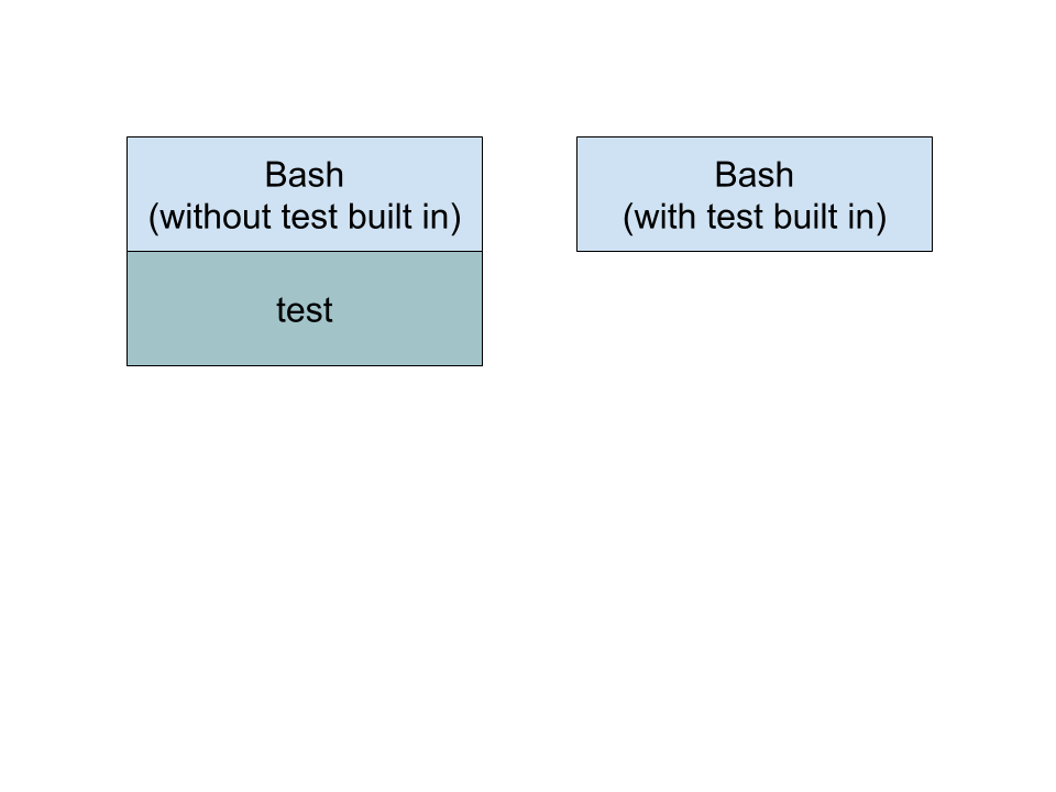
If you look at the bash manual, some things are built in and some are not. Using built ins ought to be faster than spawning a new program. For example, consider a line like:
if [ $a == $b ]
Some shells use a program named “test” to handle the square brackets. This causes a new program to launch. Modern bash provides this as a built in to help speed script execution and make it more efficient. However, you can disable it if you want to benchmark the difference. In general, you can disable a built in using “enable -n XXX” where XXX is the built in you want to disable. Use no options to enable it. Just entering the command with no arguments at all will give you a list of built in commands or use the -p option, if you prefer.
 However, there’s more to it than that. If you have some common operation that takes a lot of overhead, you can write the code in a language such as C and ask the shell to load it as a shared object and then treat it as a built in. The technique is a little involved, but it shows the versatility of the shell. You can find an example that adds a few built in commands to bash in this article. For example, the code posted makes things like
 cat and tee part of the shell, as well as creating new commands.
Exotic Solutions
We’ll admit, that last solution is a bit exotic. However, there are other things you can do. You might create a persistent server and communicate with it using a named pipe to avoid running new code. When disks were slow, you could experiment with keeping frequently used programs on a RAM disk. Today, caching ought to do that almost automatically, but perhaps not in every scenario.
Sometimes just cleaning up your code can help. Imagine this:
cat "$1" | grep "$target"
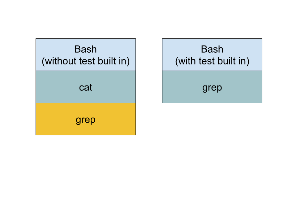
This spawns two processes, one for cat and one for grep. Why not just say:
grep "$target" "$1"
Of course, the ultimate is to simply not use a shell script. Almost any programming language will have a richer set of things it can do without launching an external program. A compiled or semi-compiled language is likely to be faster and even will help you optimize.
Shell scripts are useful to a point. It is fun, too, to see just how far you can stretch them. However, if you are really that worried about efficiency or speed, this might be the best answer of all.
source https://hackaday.com/2019/12/30/linux-fu-leaning-down-with-exec/
r/IDontWorkHereLady – “There Was a Fire, You Can’t Have a Burger and Coke!”
NEVER do this to a man
10 Cool Free Programs You’re A Fool For Not Using
Gifs With Sound 🔥35🔥 Maybe Memes
36C3: All Wireless Stacks Are Broken
Your cellphone is the least secure computer that you own, and worse than that, it’s got a radio. [Jiska Classen] and her lab have been hacking on cellphones’ wireless systems for a while now, and in this talk gives an overview of the wireless vulnerabilities and attack surfaces that they bring along. While the talk provides some basic background on wireless (in)security, it also presents two new areas of research that she and her colleagues have been working on the last year.
One of the new hacks is based on the fact that a phone that wants to support both Bluetooth and WiFi needs to figure out a way to share the radio, because both protocols use the same 2.4 GHz band. And so it turns out that the Bluetooth hardware has to talk to the WiFi hardware, and it wouldn’t entirely surprise you that when [Jiska] gets into the Bluetooth stack, she’s able to DOS the WiFi. What this does to the operating system depends on the phone, but many of them just fall over and reboot.
Lately [Jiska] has been doing a lot of fuzzing on the cell phone stack enabled by some work by one of her students [Jan Ruge] work on emulation, codenamed “Frankenstein”. The coolest thing here is that the emulation runs in real time, and can be threaded into the operating system, enabling full-stack fuzzing. More complexity means more bugs, so we expect to see a lot more coming out of this line of research in the next year.
[Jiska] gives the presentation in a tinfoil hat, but that’s just a metaphor. In the end, when asked about how to properly secure your phone, she gives out the best advice ever: toss it in the blender.
source https://hackaday.com/2019/12/30/36c3-all-wireless-stacks-are-broken/
How to make an Infinite Villager Breeder plus Bee Farm & Carrot Farm ALL IN ONE in Minecraft 1.15
Random Videos #20
3D Printed Robot Arm
No One Can Beat a Shaolin Master and Here Is Why
Ultimate DIY 60,000mAh Power Bank (222Wh)
Parallel Pis for Production Programming; Cutting Minutes and Dollars Off of Assembly
Assembly lines for electronics products are complicated beasts, often composed of many custom tools and fixtures. Typically a microcontroller must be programmed with firmware, and the circuit board tested before assembly into the enclosure, followed by functional testing afterwards before putting it in a box. These test platforms can be very expensive, easily into the tens of thousands of dollars. Instead, this project uses a set of 12 Raspberry Pi Zero Ws in parallel to program, test, and configure up to 12 units at once before moving on to the next stage in assembly.
Fixing Fixture Bottlenecks
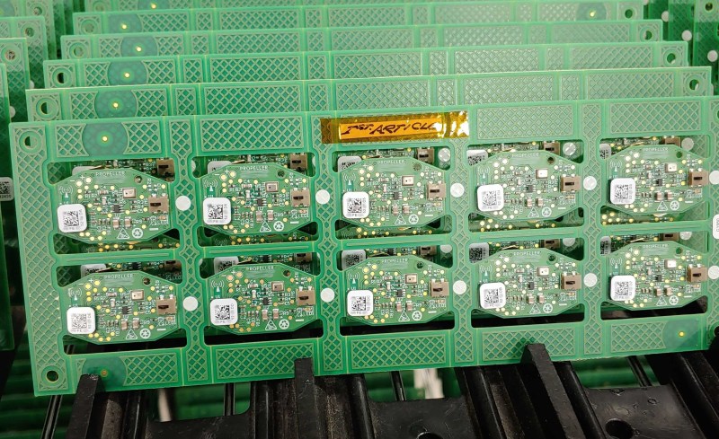
The company where I work, Propeller Health, develops IoT products that are assembled in a way similar to many other companies; there is a circuit board and a plastic enclosure. The bare PCBs go through SMT twice (components on the front and back), then they go through ICT (In-Circuit Test) where they are programmed and pogo pins on each of the test points verify all components on the circuit. They are also given a unique MAC address for Bluetooth based on a 2D barcode sticker placed on the board after SMT. After that they are assembled into the plastics and run through a functional test fixture before they are put into inventory mode and boxed. We have a product line of around a dozen different devices, and each uses a different PCB and enclosure.
Production runs need test and programming fixtures, a topic i wrote about a few years ago. To increase scale and reduce costs we started working more closely with our contract manufacturer to identify and fix the bottlenecks in the assembly line process, and we noticed that the ICT stage was taking 6 minutes for a panel of 6 boards. The ICT section itself was relatively fast, but the firmware programming and mac programming were taking a long time because the test platform was not capable of multiple simultaneous serial port connections.
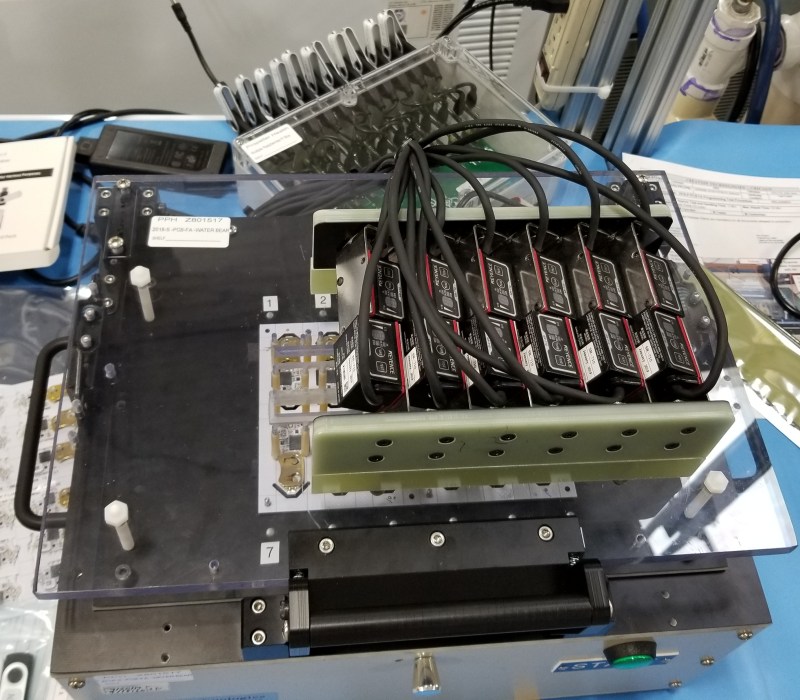
This was a $30k fixture with 6 Segger programmers, 6 Keysight scanners, sitting on top of a $100k Teradyne platform, and it was our biggest bottleneck and greatest expense. Further, each device in our product line requires different fixturing. The combination of these expensive fixtures and slow cycle time was making our COGS (Cost Of Goods Sold) untenable.
On an assembly line, time is literally money, as every cycle time for every operator on the line is measured and added to the cost of the product. Reducing a cycle by even a second adds up quickly over a volume of thousands. Over 10k units, 2 second reduction is 6 hours of labor, at $15/operator hour is $.01/unit, and CMs, especially US based ones, are charging more than $15/hour. Having a 6 minute cycle time for 6 pieces was ripe for improvement.
Stage One – Arduino
The first stage was more a proof of concept. Could we pull some of the functionality off of the expensive ICT fixture onto a cheaper faster fixture so that we could scale in serial instead of buying another fixture to scale in parallel?
For this stage we implemented a feature in our firmware we call self-test, which is similar to a JTAG boundary scan. Rather than placing pogo pins on every net, we put a feature into the firmware to run a self-test on as many components as it could, and report the results over serial. This way we’d be able to connect only with the power and UART pins and get a complete and very fast readout of what exactly failed. Eight Arduinos connected via a USB hub to a tablet PC with a custom Python script and interface was the solution.
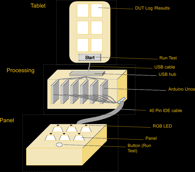
A single 40pin IDE connector was enough to have power, an RGB LED, RX, TX, and a single button that would kick off the cycle for all 8 at once. The Arduino would request a self-test from the DUT (Device Under Test), which would test its components and report back. Tests included verifying that sensors were reading values within an expected range, but also turning on the LED and buzzer and measuring the voltage drop to verify that outputs worked as well.
This worked, and proved the concept of creating a box with most of the electronics paired with a simple customized fixture for the panel, but it wasn’t enough. Pulling out some of the circuit tests was insufficient to reduce time significantly. We needed to pull out more tasks.
Stage Two – Raspberry Pi
One of the more expensive parts of the ICT fixture was the Segger J-Link programmers. If we could pull out programming from ICT with something cheaper, we could reduce fixture costs significantly. Many chip manufacturers offer programming at the factory so that your microcontrollers come on a reel with your firmware pre-programmed. This is useful when you don’t trust your manufacturer or don’t want to have a special fixture for programming, but it does have an added cost, and there’s a lead time, and changing your firmware is more difficult, and you can’t use that part on any other product.
Programming in house had a lot of appeal for us, simplified our supply chain, and gave us more flexibility to change our firmware and shift inventory as needed. Enter the Raspberry Pi Zero W and OpenOCD. The Raspberry Pi is more than capable of running OpenOCD to program a microcontroller, and was surprisingly easy to configure and get running. It also had a serial port and GPIO for controlling WS2812B LEDs, and was small enough that it was easy to put a bunch in a box.
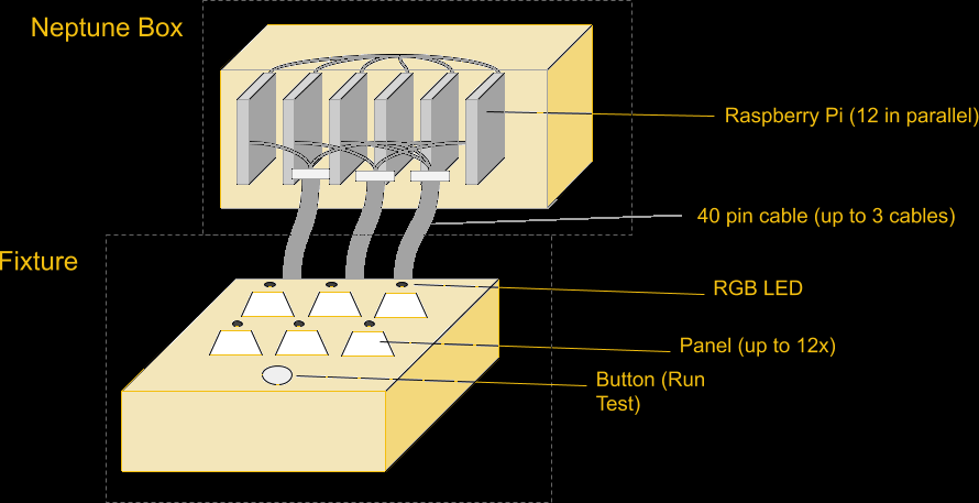
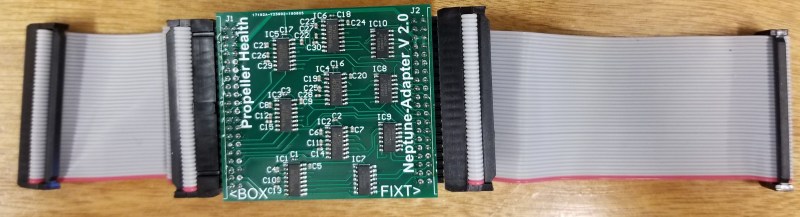
The connector expanded to a second 40pin IDE cable, and support for up to 12 parallel units, the size of our largest panels. Each Pi runs completely independently, without communicating with each other. The only thing they have in common (besides power supply) is that all 12 are connected to the same pushbutton on the front of the fixture. The button is used by the operator to start the programming cycle, but each Pi runs its process independently.
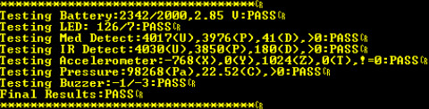
Drawing on the Arduino experience further, the Raspberry Pi process would first program the unit, then verify it was programmed correctly by communicating over the UART, then execute the self-test on the device, which would test the accelerometer, microphone, IR sensors, LED, buzzer, etc, and report back the results and a PASS/FAIL status. We had accomplished our primary goal of removing a significant portion of the process time and cost from the ICT fixture, but we could go further.
Stage Three – Adding Features
With the addition of cameras to the fixture, we could read the MAC address on the sticker and use the serial port to program the MAC address into the unit. This allowed us to tie our process to the MAC address that was used to track the unit through the rest of the assembly line.
If you’re wondering why we didn’t pre-assign numbers and then have the operators put on the correct number, it comes down to reducing the chances for operator error. Giving the operator a sheet of stickers and telling them to put them on the units is way less error-prone than having them put specific stickers on specific units, and faster than printing out barcodes one at a time for individual units.
Next we added the unique key stored on the unit for authenticated communication. The pi generates a 64 byte key, programs and verifies that key on the sensor, then encrypts the key and stores it in the log file. That key gets decrypted on our servers and allows us to communicate with our sensors.
In addition, we added thorough logging; a system log tracks the version numbers of the script, config file, and firmware file, and a separate file logs each cycle with diagnostic data about each stage of the process. These logs are stored on a thumb drive, but also uploaded regularly to a secure FTP so that we can import the logs (and the encrypted keys) immediately, as well as keep tabs on our CM and monitor when they are running our jobs and help them diagnose any problems.
We also made all of this run off a thumb drive. On boot the pi starts a Python script whose sole job is to wait for a thumb drive to be inserted, then run the script on that thumb drive. The thumb drive contains the main Python script, config file, firmware hex file, and logs. This way we have a single box that is completely agnostic to the assembly line, and then we have a dozen thumb drives that stay with the line for that particular device. We don’t need an interface to the pi because we can just plug the thumb drive into a computer to configure it however needed. Anything that makes the job easier for operators makes the assembly line run smoother, and saying “plug these into the back of the box” worked pretty well.
At this point we could program the microcontroller, then execute a self-test, then program the MAC address, and generate a unique key, and output to an LED the status of the process (green for success, yellow for in progress, and red for failure), and save the log to a file. This shaved MINUTES off the cycle time. Before, a panel of 12 was split in two, then each half went through the ICT fixture for 6 minutes, for a total cycle time of around 12 minutes for 12 devices. After the change, we had the full panel of 12 take under a minute, then split and spend under 2 minutes each at ICT. We went from 12 in 12 minutes to 12 in 5 minutes, with more control over the process and greater transparency.
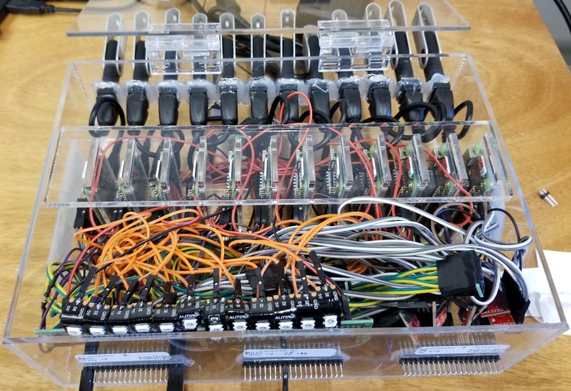
Stage Four – Neptune is Alive
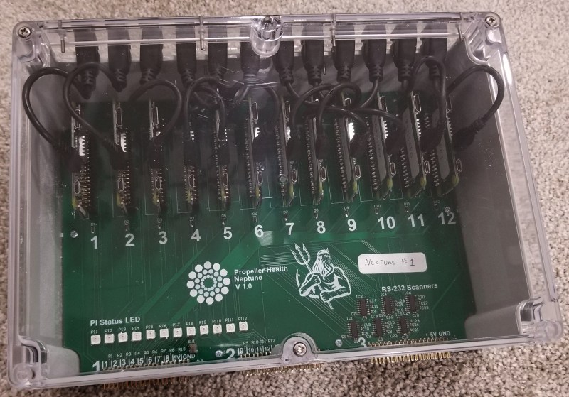
After our first box worked, our CM asked for more so they could service multiple assembly lines, plus have backups and one for test/development. The design was formalized, we found a new enclosure that could be modified easily, and designed a PCB. Total cost for all components is around $500, and the PCBs are easy enough to assemble by hand in a couple hours. We called the project Neptune and the boxes started coming together. Now we have plenty of Neptune boxes, and we have a spec for our fixture developer that allows them to have a very simple circuit they can replicate over and over. Fixtures are rugged beasts that require special knowledge and experience that we don’t have and don’t want to develop, so we outsource that part. The most recent fixture worked immediately with no changes, which is usually nearly impossible.
Stage Five – Changing Cameras
A MAC address sticker is placed on every unit after SMT, but this address must be programmed into the microcontroller itself. To do this, a barcode scanner is used. This is a production environment, and we are packing 12 scanners into a small space, and the scanners must accurately and reliably detect a 2D barcode about 1/2in^2, so not just any scanner will do.
Originally, on the suggestion of our CM, the fixtures were outfitted with Keyence scanners. After we discovered that these are $1400 each, we realized a huge potential for cost reduction. Each of our fixtures has 10-12 devices per panel, so replacing the Keyence scanners with $250 Zebra scanners was an immediate gain. The downside is that our Neptune PCB was designed for RS232 communication with the Keyence scanners using only 2 UART pins, and the Zebra scanners required 5V logic levels with hardware RTS/CTS pins as well. Fortunately we were able to build a cable with an inline circuit that contained an ATtiny84 for each of the cameras.
With a small config file change, we can tell the system to use a slightly different communication protocol. The Pi sends a serial signal, which is stepped up to RS232 inside the Neptune box, then on the cable dongle it steps down to 5V, goes into the ATtiny, where it is parsed, and if the desired signal then it sends a pulse to the trigger pin of the Zebra scanner, which then scans the barcode and sends the result back to the dongle, where it is stepped up to RS232 and heads back to the unit. The dongle meant that we didn’t have to change anything about the box, and the fixture didn’t have any additional circuitry as well.
Results
The results of Neptune have saved the company a lot of money in fixtures and in unit cost, improved our scalability, given us greater transparency in our production, added features, and made development of new features easier. The Raspberry Pi was instrumental in this, as was OpenOCD. We learned a lot and developed some techniques that would likely be valuable to anyone else doing manufacturing of electronic devices. We’re still working out exactly how we can share this without compromising security or trade secrets, but this is our first step.
Dyeing For Emeralds! – Skyblock In Minecraft 1.15: Episode #13
Image Sensor from Discrete Parts Delivers Glorious 1-Kilopixel Images
Chances are pretty good that you have at least one digital image sensor somewhere close to you at this moment, likely within arm’s reach. The ubiquity of digital cameras is due to how cheap these sensors have become, and how easy they are to integrate into all sorts of devices. So why in the world would someone want to build an image sensor from discrete parts that’s 12,000 times worse than the average smartphone camera? Because, why not?
[Sean Hodgins] originally started this project as a digital pinhole camera, which is why it was called “digiObscura.” The idea was to build a 32×32 array of photosensors and focus light on it using only a pinhole, but that proved optically difficult as the small aperture greatly reduced the amount of light striking the array. The sensor, though, is where the interesting stuff is. [Sean] soldered 1,024 ALS-PT19 surface-mount phototransistors to the custom PCB along with two 32-bit analog multiplexers. The multiplexers are driven by a microcontroller to select each pixel in turn, one row and one column at a time. It takes a full five seconds to scan the array, so taking a picture hearkens back to the long exposures common in the early days of photography. And sure, it’s only a 1-kilopixel image, but it works.
[Sean] has had this project cooking for a while – in fact, the multiplexers he used for the camera came up as a separate project back in 2018. We’re glad to see that he got the rest built, even with the recycled lens he used. One wonders how a 3D-printed lens would work in front of that sensor.
VGA Signal in a Browser Window, Thanks to Reverse Engineering
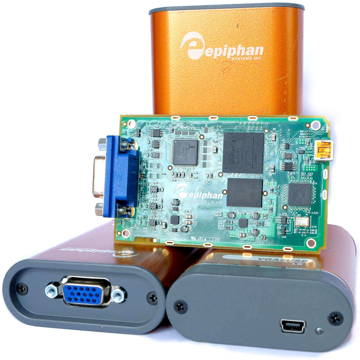
[Ben Cox] found some interesting USB devices on eBay. The Epiphan VGA2USB LR accepts VGA video on one end and presents it as a USB webcam-like video signal on the other. Never have to haul a VGA monitor out again? Sounds good to us! The devices are old and abandoned hardware, but they do claim Linux support, so one BUY button mash later and [Ben] was waiting patiently for them in the mail.
But when they did arrive, the devices didn’t enumerate as a USB UVC video device as expected. The vendor has a custom driver, support for which ended in Linux 4.9 — meaning none of [Ben]’s machines would run it. By now [Ben] was curious about how all this worked and began digging, aiming to create a userspace driver for the device. He was successful, and with his usual detail [Ben] explains not only the process he followed to troubleshoot the problem but also how these devices (and his driver) work. Skip to the end of the project page for the summary, but the whole thing is worth a read.
The resulting driver is not optimized, but will do about 7 fps. [Ben] even rigged up a small web server inside the driver to present a simple interface for the video in a pinch. It can even record its output to a video file, which is awfully handy. The code is available on his GitHub repository, so give it a look and maybe head to eBay for a bit of bargain-hunting of your own.
source https://hackaday.com/2019/12/30/vga-signal-in-a-browser-window-thanks-to-reverse-engineering/